
Abstract
The introduction of robotic surgery within the operating rooms has significantly improved the quality of many surgical procedures. Recently, the research on medical robotic systems focused on increasing the level of autonomy in order to give them the possibility to carry out simple surgical actions autonomously. This paper reports on the development of technologies for introducing automation within the surgical workflow. The results have been obtained during the ongoing FP7 European funded project Intelligent Surgical Robotics (I-SUR). The main goal of the project is to demonstrate that autonomous robotic surgical systems can carry out simple surgical tasks effectively and without major intervention by surgeons. To fulfil this goal, we have developed innovative solutions (both in terms of technologies and algorithms) for the following aspects: fabrication of soft organ models starting from CT images, surgical planning and execution of movement of robot arms in contact with a deformable environment, designing a surgical interface minimizing the cognitive load of the surgeon supervising the actions, intra-operative sensing and reasoning to detect normal transitions and unexpected events. All these technologies have been integrated using a component-based software architecture to control a novel robot designed to perform the surgical actions under study. In this work we provide an overview of our system and report on preliminary results of the automatic execution of needle insertion for the cryoablation of kidney tumours.
1. Introduction
The introduction of minimally invasive surgery (MIS) first and, more recently, of surgical robots, has brought new perspectives to surgery and has significantly improved the quality of many surgical procedures (e.g., [1, 2, 3, 4, 5]. However, current surgical robots are not the final answer to surgeon's demands in terms of (1) high motion accuracy (to enable interventions that would otherwise be impossible), (2) dexterity, (3) presenting information in a more meaningful way (to improve the quality of the clinical result, e.g., virtual fixtures, active constraints) [6]. In fact, they are teleoperated devices without any embedded autonomy (e.g., the Da Vinci by Intuitive Surgical [7] and the MiroSurge developed by Deutschland für Luft- und Raumfahrt (DLR) [8] and therefore performance-bound by the perception and dexterity of their human operators.
Although it is well known that automation has been successfully used to enhance a great variety of human activities from aircraft control to manufacturing, the whole area of autonomous interaction of surgical tools with biological tissues is rather unexplored. In the applications where it has been used, automation has increased safety, accuracy, reproducibility, and has decreased human fatigue [9, 10]. Thus, we hypothesize that similar benefits could also be gained by introducing automation to specific aspects of surgery, provided that we can successfully solve the challenges of this concept [11]. In fact, reports in the general press [12] and in the FDA listing of safety alerts for medical devices [13] indicate the increasing occurrence of potentially dangerous situations during robot-assisted procedures.
In this paper we report the results achieved during the FP7 European project Intelligent Surgical Robotics (I-SUR) addressing the autonomous execution of basic surgical actions. Such technology will in the future allow surgeons to focus only on the most difficult aspects of the intervention, leaving the basic tasks to the autonomous system. In this paper we will focus on the puncturing task and in particular on the needle insertion for the cryoablation procedure. This procedure requires high accuracy and precision that a robotic system integrated with a sophisticated sensing system can guarantee.
To prove the feasibility of our approach to this problem, we develop general methods for a cognitive surgical robotic architecture capable of combining sensing, dexterity, and cognitive capabilities to carry out this action autonomously. The algorithmic part is integrated with a novel, high dexterity robot specifically designed and fabricated during the project.
Currently we are improving the robotic platform to be able to autonomously execute other surgical tasks such as cutting and suturing. It is worth highlighting that several design choices made at the very beginning of this project (and reported in this paper) were also driven by these tasks to assure enough dexterity and manipulability, and to exploit the re-usability of common software components.
In summary, as an area of strategic interest and high social impact, autonomous robotic surgery requires methods and models for assessing its quality and its impact in operating room (OR) procedures and instrumentation. The objective of this paper is to report the results of our initial efforts to
design and fabricate a high accuracy robotic platform based on a macro-micro concept [14],
develop an integral diagnostic-planning-intervention workflow characterized by information and communication technology (ICT) methods and models.
The paper is organized as follows. In Section 2 we analyse the medical background relevant to the specific surgical action we want to automatize. In Section 3 the design of high accuracy phantom model of the human abdomen is described whereas Section 4 describes the design of a new surgical robot. Sections 5 and 6 present the development of new methods for interactive planning of surgery in deformable environments, intervention execution and monitoring, and of new methods for real-time data processing and medical situation awareness, respectively. In Section 7 the surgical interface is presented. These new systems and methods have been integrated and experimentally tested in Section 8. Section 9 discusses the legal implication and challenges of autonomous robotic surgery. Finally, conclusions are drawn in Section 10.
2. Medical background
The surgical action we will analyse in this paper is puncturing, and to identify a specific procedure we will focus on the insertion of a needle for the cryoablation of kidney tumours. Puncturing is defined as the act of penetrating a biological tissue with a needle, aiming at reaching a specified target point.
2.1 The cryoablation procedure
Percutaneous cryoablation of a small tumoural mass in the kidney is the least invasive treatment for kidney cancer based on thermal ablation, which aims at destroying neoplastic tissues through a thermal shock caused by short cycles of freezing and thawing.
The percutaneous approach, in contrast with open or laparoscopic surgery, is less invasive, decreases morbidity and ensures high efficacy by accurately targeting the cancer while preserving the healthy adjacent structures [15, 16].
Percutaneous cryoablation is performed using a tool called cryoprobe which is directly introduced through the skin towards the kidney tumour with the aid of clinical imaging devices (computer tomography CT, magnetic resonance imaging MRI, ultrasound US). Cryoprobes are hollow needles, similar to biopsy tools, whose temperature is conditioned by fluids circulating inside, generally argon for cooling and helium for heating. The very low temperature generated around the tip allows the freezing of the surrounding tissue, creating an iceball around the tumour. Rapid freezing and thawing cycles induce irreversible damage of the tissue within the iceball.
2.2 How robotics can improve the procedure
The most important issue for a puncturing task is to safely and correctly reach the target point. In fact the precision of insertion of the needle tip near the centre of the tumour is strictly correlated to the success of the treatment. For this reason, the cryoablation procedure can be improved by exploiting the intrinsic high accuracy and repeatability of robotic devices and the pre- and intra-operative images of the patient's anatomy.
Several experiences on robot-assisted percutaneous procedures have been reported in the literature in recent years. Good results have been obtained in terms of accuracy [17, 18], number of access attempts, time to successful access, and estimated blood loss and complications, compared to standard procedures where the radiologist has to rely on his/her experience [19]. The standard procedure usually requires several CT scans during the needle insertion to assess its actual position, exposing the patient to a considerable amount of radiation [20]. Thus an autonomous system able to plan and execute a puncturing procedure, managing possible hazardous events and reducing CT scans, represents a significant improvement in patient safety. Furthermore, this technology could be easily exploited in different surgical applications where accuracy and precision are important factors.
2.3 Medical and procedural requirements
To define the requirements of the robotic system it is necessary to analyse
how the procedure is executed by a surgeon, and
how the robot can perform the same task interacting with the operator and the partially unknown environment.
This analysis is used to ‘translate’ the surgical knowledge, professional experience and anatomical constraints into a mathematical formalism for the design of the cognitive robotic architecture in all its aspects: control, sensing, dexterity, etc. Although most efficient automation is not done by duplicating human movements, here we need to ensure that a surgeon can continue the task by teleoperating the robots (teleoperation mode) in case of emergency. For this reason we strive to preserve the dexterity and cognitive aspects of the manual task.
Preliminarily, the surgical task is partitioned into subtasks and modelled as a state diagram to represent the sequence of actions to be performed. Then we select the critical variables and parameters involved in the procedure (i.e., distance to target, maximal force applied to the skin and so on) needed to trigger the transitions among the states in normal and emergency situations. Data collected by the sensing system during the intra-operative phase are used to compute these parameters and autonomously detect unexpected events or dangerous situations.
The pre-operative analysis is used to locate the tumour and to plan the insertion. The planning has to compute the end points of the cryoprobes so that the volume of the tumour is completely covered by the iceball. As a precautionary principle, cryoprobes are placed in order to generate ‘killer’ isotherms extending some millimetres beyond tumour edges. On the other hand, healthy tissue has to be preserved from the ablation as much as possible. Hence, we developed an optimal planning strategy that achieves whole tumour coverage (hard constraint) and minimizes the damage of surrounding healthy structures (soft constraint).
During the planning we define a set of forbidden regions from where the iceball has to be kept away. A safety distance of 5-10 mm is a safe distance to the bowel, ribs, nerves, spleen, liver and ureters. For this reason, a high accuracy robotic system is required to insert the needle with a position error smaller than 1 mm. Moreover, the sensing system should be able to detect critical/characteristic events such as skin penetrated, tumour hit, tumour passed and forbidden region touched.
To verify the plan quality, we developed a cryoablation simulator that computes the nominal trajectories and verifies the satisfaction of the constraints [21]. Figure 1 shows the interface of the simulator.

Graphical user interface of the cryoablation simulator from where the operator can load the CT scans of the patient
However, to compensate for registration mismatch, US guidance is required to monitor the needle path during the insertion. This is the reason for which a second robotic arm holding a US probe is needed. The control architecture has to coordinate the motion of the two arms during the procedure and avoid collisions.
The system should be able to understand how the tools are operating and what is happening on the surgical table. The accuracy of the needle insertion and the reliability of the procedure are, for the professional users, the most tangible benefits an autonomous system should offer. These characteristics are strictly related with (1) the correctness of the description of the surgical knowledge into technological processes, (2) the trustworthiness of procedural and anatomical models, (3) the acquisition of relevant data and their right interpretation, (4) the prompt detection of dangerous events and the possibility to put in action countermeasures to mitigate their effects (such as re-planning of the trajectories, teleoperation of the robots).
3. The model of human abdomen
For puncturing tests with US guidance a kidney box phantom was developed to represent the right side kidney of a human being and its surrounding structure. In order to increase the anatomical reality, a human CT scan was used to reconstruct the spatial location of the organs. Besides the kidney, the reconstruction considers also a section of liver, the ascending stretch of colon, ribs covering the liver, a simplified layer of skin and fat representing the right back side of the abdomen. The reconstruction of the models of the organs from the CT scan was made using 3D Slicer by segmenting a quarter of the right side of the abdomen as shown in Figure 2.
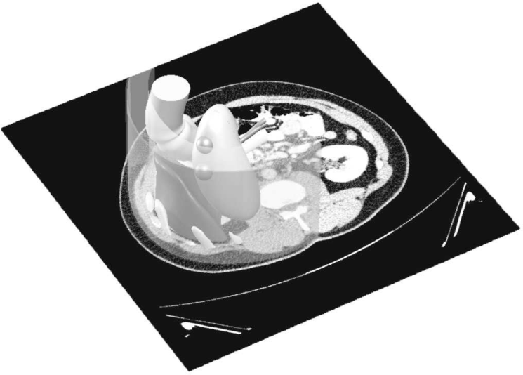
Region of segmented organs
The segmented organs were then imported into a CAD software (SolidWorks). A watertight box surrounding the organs, fixators for the organs, moulds for casting the organs and placement of the markers were designed in the CAD software. Two 20mm tumours were added to the lower pole on the posterior face on the kidney model. The fixators were designed to keep the liver, kidney and fat layer in place in the box.
The organ moulds were made of Polylactic Acid (PLA) using a rapid prototyper 3DTouch (manufactured by Bits from Bytes Inc). Ribs and the fixators for the liver, kidney and fat layer were fabricated in the same way.
The liver, kidney and fat layer were casted using gelatin mixtures which allowed the artificial organs to be visible on US images and CT scans. The preparation of the gelatin mixtures is described in [22]. Before casting the organs, fixators with reinforcing thin mesh were placed into the moulds. Tumours of the kidney were casted from clear gelatin mixture and were later fixed on the surface of the casted kidney by melting the gelatin between two bodies. The tumours were also covered with silicon (Elite Double 22, Zhermack SpA) mixed with graphite flakes to enhance border visibility. The box surrounding the organs was prepared from parts milled out from plywood and assembled using plastic bolts. For the descending colon we used a simple cylindrical piece of fabric attached to the phantom walls.
The liver was fixed on the wall after casting the box with bolts. The kidney was placed on two plastic rods on the box cover to stay in the middle of the box. The fat layer was fixed on top of plastic supports, then covered with coloured silicone (Dragon Skin series silicone) to represent human skin, and finally fixed from outside with a plastic strip.
To calibrate the intra-operative US images with the preoperative CT scan, four markers were placed inside the kidney box phantom behind the organs (so that they did not shadow the organs) and as far away from each other as possible (for increasing the calibration accuracy). Markers were made of 10 mm rubber spheres fixed on 3 mm plastic tubes to the outer wall of the box phantom. Positioning of the markers can be seen in Figure 3. The visibility of the markers was further enhanced by painting the rubber balls with silicon (Elite Double 22, Zhermack SpA) mixed with graphite flakes.
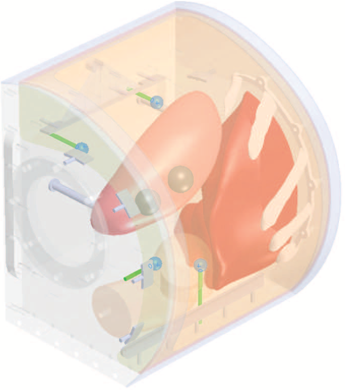
Placement of the US/CT markers: four blue balls on greed rods
The surrounding space around the kidney, liver and colon was filled with water which allows the US-based inspection of inner structures of the phantom. It was poured into the phantom box through the round opening, which was later sealed with transparent Plexiglas. The current version of the phantom has to be kept in the refrigerator and can be used for one month before organ degradation.
4. The robotic platform
Most of the existing robotic surgical platforms dedicated to autonomously achieving parts of or complete surgical interventions have been designed for one specific task, e.g., for joint replacement surgery (ROBODOC, [24], or prostate resection (Probot 1 ), [25]). The automation of multiple surgical tasks with a single surgical platform, as described here, is a new major challenge, which motivated the design of a versatile and dexterous robotic platform.
Figure 4 shows the robotic platform for the needle insertion under US monitoring. The commercial robot UR5 [26] holds the US probe: the sensing system detects on the US images the motion of the needle to guarantee the safety of the procedure. The ISUR robot holds the needle and performs the puncturing according to the planned trajectory. During the needle insertion task, the US probe is first placed on the surface of the body, aligned with the expected needle tip trajectory, and then the needles are mounted on the robot end-effector and automatically inserted one by one.

The overall ISUR robotic platform. On the left, the UR5 robot holding the US probe; on the right, the ISUR robot holding the needle; On the operating table, the phantom of the human abdomen.
4.1 Design Considerations
In order to perform automated puncturing for cryoablation a large workspace, high structural stiffness and the ability to generate output forces of up to 15N [27, 28] are required. In contrast, cutting and suturing, which will be implemented in the future by the same platform, require a dexterous end-effector capable of holding tools and performing complex manipulations similar to the hands of a surgeon, with low interaction force and within a small workspace. The minimum workspace to perform the three surgical tasks is the volume of the human abdomen plus a frame of 15 cm allowing the safe movement of the tools. Last but not least, the design of a surgical robot should consider the limited amount of space available in the operation room, and the possible interaction with other surrounding equipment, such as ultrasound probes and supporting structures used in procedures relying on intra-operative imaging.
These requirements motivated the design of a modular robotic platform based on a macro/micro unit architecture [14], consisting of two decoupled robotic structures that can be controlled independently as well as in concert (Figure 5).

The robotic platform for automatic needle insertion. The robot consists of a macro unit (linear delta with 4-DOF, J1-J4) for gross positioning, and a micro unit (4-DOF, J5-J8) to hold and orient a cryoablation needle. The needle holder is attached via a six-axis force/torque sensor.
A macro unit with four degrees of freedom (DOF) serves as a gross positioning unit, to position the micro unit over the region of interest where the needle is to be inserted. For this purpose, a 3-DOF linear delta robot [29] was selected, as this parallel kinematics offers a rigid platform capable of carrying the weight of the micro unit, while ensuring high stiffness and positioning accuracy. The three parallelogram arms of the delta structure are actuated by three linear spindle drives. An additional DOF on the moving platform controls the rotation of the micro unit base to adjust its orientation during the surgical procedure. For the sake of convenience and space constraints, the linear delta was attached to a custom-made table 2 m in length in the first prototype. However, the arms of the delta structure could easily be flipped upwards, allowing the linear drives to be fixed to the ceiling or a supporting structure for installation in an operating room.
A dexterous micro unit capable of manipulating different surgical tools is mounted to the moving platform of the macro unit. The micro unit is based on hybrid kinematics and offers 4-DOF, mimicking the arm of a surgeon (shoulder flexion/extension, shoulder rotation, elbow flexion/extension and forearm pronation/supination). In the case of the puncturing procedure, the needle is mounted to the distal end of the robotic arm of the micro unit. The first three DOF of the micro unit are used to orient the needle and are actuated remotely (from the moving platform of the macro unit) while the fourth DOF allows rotation of the needle around its axis via a belt and pulley drive located behind the needle holder.
User Feedback Usability Survey

The needle can be easily detached from its holder to allow for the successive insertion of multiple needles. The needle holder incorporates a six-axis force/torque sensor (ATI Nano 17, ATI Industrial Automation Inc., NC, USA) to measure interaction forces and torques during insertion. For more complex surgical tasks such as suturing, the needle is replaced with a cable-actuated wrist module that provides three additional DOF (wrist flexion/extension, radial/ulnar deviation, and a gripper) and can be easily attached to the force/torque sensor. A second arm with the same DOF can further be mounted to the moving base of the macro unit, resulting in a versatile, bimanual robotic surgical platform with 18-macro unit, resulting in a versatile, bimanual robotic DOF.
4.2 Control, Safety and Performance
Position sensing is achieved through encoders located at the level of each actuator, and through potentiometers along the drives, providing a redundant position measure for safety purposes. The end-effector position is computed by solving the kinematics of both the macro and micro units independently, and then combining them. The control architecture of the robotic surgical platform is organized in a hierarchical way. A low-level controller performs position and velocity control in a cascaded manner [30] at the joint level, and is used for trajectory following. A high-level controller implemented on a separate PC generates the commands for the automatic execution of the surgical tasks, and includes the reasoning and cognitive processes required for such tasks (the control architecture and the reasoning module will be described in the following Sections 5 and 6, respectively). The low-level control layer is implemented in real-time LabVIEW 2013 (National Instruments, USA), and runs on a PC with an eight-core Intel i-7 (3.4 GHz) processor. For optimal control of the multi-DOF robot, joint/velocity control runs at 10 kHz on an integrated field-programmable gate array board, while trajectory following is performed at 2 kHz on the PC.
Safety is a major requirement in robotic surgery. In the present scenario of a puncturing procedure, special care has been taken to avoid collisions with the robotic arm holding the ultrasound probe (see Figure 4) and the surgical table (both during the planning and the real execution of the intervention). This is achieved by constantly monitoring the interaction forces/torques from the sensor integrated into the needle holder, as well as by monitoring motor current, position and velocity at the level of each joint. In addition to software limits (on position, velocity and current) implemented in the low-level controller, mechanical end-stops are integrated at the level of each joint. During normal operation, actions performed by the robot will be visualized on the surgical interface together with plots of the most important sensor readings, allowing the supervising surgeon to intervene at any moment to stop the system through emergency switches or take over the control through the teleoperated mode.
5. The control architecture
In this section we describe the control architecture that interacts with the low level controller described in the previous section (by sending reference positions and receiving force measurements) and with the reasoning module described in the next section (by sending and receiving events).
Validation-oriented design is mandatory for the application domain of surgical robotics. Therefore, design specifications for control algorithms and supervisory/coordination logic have been formalized using a requirements engineering approach, which is an increasingly recommended practice for safety-critical systems design (see for example the guidelines in [31]. The methodology applied in this work, described more precisely in [32], is as follows:

5.1 Supervisor layer
The autonomous robotic system is supervised and controlled by the following three modules, corresponding also to software units deployed on different computational platforms: a Surgical Interface (described in Section 7), the Robot Controllers, and the Sensing system with Reasoning and Situation Awareness capabilities (described in Section 6).
The interaction among such system components has been specified with the help of UML sequence diagrams, which represent scenarios compatible with a given collaborative behavioural specification. As an example, Figure 6 shows an admissible scenario for the cryoablation execution, focused on needle insertion under US-based monitoring.

UML Sequence Diagram of the interaction among system components during the needle insertion
The scenario specifies the initial setup of the surgical task, in which preoperative medical imaging data are processed by the cryoablation planning algorithm presented in [21], whose result is the optimal placement of cryoprobe needles to obtain full tumour coverage with the expected iceball, without interferences with other organs (i.e., forbidden regions). The needle placement is referred to the centre of the tumour, therefore the task plan, once validated by the surgeon, must be adapted to the operative scenario by means of the registered coordinate transformations calculated by the sensing/reasoning module.
The complete behavioural specification of the robot control and supervision units is given by UML state diagrams associated to the control logic for the robot holding the needle and for the robot holding the US probe. Figure 7 shows the hierarchical state machine related to the robot inserting the needle.

UML state diagram of the behavioural specification for the controller of the robot holding the needle
The UML state diagrams are translated in the programming language Lua [39] and then loaded by a component of the distributed system architecture. This component acts therefore as a supervisor of the control architecture [40].
The hierarchical features of UML state diagrams make it possible to embed exception handling mechanisms by means of transitions exiting composite states. In both state machines, in fact, the robotic task can be stopped because of an exception event that can be triggered either by the surgeons, through the surgical interface, or by the sensing/reasoning and situation awareness module. In particular, the latter is in charge of detecting if the needle is too close or even touching a forbidden region or any force value measured by the sensors exceeds a safety threshold. Whatever the exceptional event, if the task execution can be restarted after appropriate validation of the surgeons, the transitions marked by the e_taskRecovered event are executed. If necessary, the system allows the surgeon to switch to a teleoperated mode.
5.2 System architecture
The system architecture is organized according to the classification of system components shown in Figure 8. Such a classification reflects the definition of the three main modules previously described, but provides a further decomposition of software components into those whose behaviour is mainly event-driven and those performing data-driven computations.

General scheme of the proposed control and coordination software architecture
The experimental setup described in Section 8 includes two different robots as shown in Figure 4: the macro/micro robotic platform used to perform the needle insertion and the UR5 robot used to hold and place the ultrasound probe. It follows that the planning and control system is composed of two similar control loops, one for each of the two robots. These control loops interact indirectly by exchanging events with the task supervisor.
Based on the planning created using the preoperative knowledge, the control module has to:
generate a valid Cartesian path (start pose) from the current robot pose and a desired one (goal pose)
parametrize the path in accordance to some constraints of the motion (i.e., maximum velocity and acceleration)
control the robot to make it follow the desired trajectory
Several distributed software frameworks are available in the literature to implement such architecture. Among others, the most used are the robot operating system [41] and the open robot control software [42]. The latter has been preferred because of its real-time properties [43].
As described in [44], an Orocos component is a basic unit of functionality that executes one or more (real-time) programs in a single thread. The high-level control architecture reported in Figure 9 is composed by five components:

Interconnection scheme of robot motion panning and control components
5.3 Teleoperation mode
When the cognitive system is no longer able to complete the execution of the surgical procedure due to unexpected or unmanageable events, the surgeon has to take over the control of the surgical robots. We implemented a two-layered bilateral control architecture that ensures safe behaviour during the transition between autonomy and teleoperation and still retains high performance control after the switch, [46].
When the surgeon switches the robot platform from an autonomous mode to a teleoperated mode, it is likely that a kinematic mismatch occurs between the pose of the master console and that of the surgical robot (i.e., the slave robot). This mismatch can impose a high workload on the surgeon to mentally compensate the offset, and can therefore lead to risks for the patient because of unintentional motions transmitted to the robot. These problems are highly undesirable because the teleoperation mode is activated during critical situations, and mistakes in the teleoperation can cause severe injury to the patient. While many bilateral teleoperation control strategies ensuring efficient and safe behaviour have been proposed in the literature [47], to the best of the authors' knowledge there are no bilateral teleoperation systems where the safely switching between autonomous and teleoperated modes and kinematic mismatches compensation are proved in formal ways [48]. The passivity-based interactive control architecture shown in Figure 10 allows the implementation of safe and stable time-varying interactive behaviours and a transient-free kinematically-compensated bilateral teleoperation of a surgical robot.

The two-layer architecture for the pose offset compensation. In the Transparency Layer, the desired coupling forces. These commands are sent to the passivity layer, the role of which is to check and guarantee the passivity of the total system.
6. The high level reasoning module
This section reports on the design of the real-time reasoning and situation-awareness module. This module uses intra-operative real-time sensory data and a priori medical knowledge to identify the task evolution and to trigger events for driving the control architecture. The module addresses the following topics: alignment of the robotic system, registration of the subsystems (i.e., robots, phantom, US imaging), sensing techniques and, finally, development of the algorithms for reasoning and situation awareness.
6.1 Registration
The surgical scene in Figure 11 is composed of several objects: the UR5 robot holding the US probe, the ISUR robot holding the needle, the phantom of the human abdomen and the tracking system. In order for the robots to work together and to recognize the location of the phantom in the surgical scene, the robots and the phantom must be registered in a common coordinate system. This common coordinate system will be called in the following world frame. This preliminary phase is extremely important because it affects the overall accuracy and precision of the system and has to be done before starting any surgical procedure [49, 50].

The four steps in the registration procedure, marked 1 to 4. A and B are the forward kinematics of the ISUR robot and the UR5 robot.
A 6-DOF tracking system is used to estimate the transformation matrices between the local coordinate frames of the robots and the phantom. We used an Accutrack 500 from Atracsys LLC, Switzerland which is an active tracking system with a root mean square (RMS) position error of 0.19 mm [51]. The registration procedure goes through four steps as shown in Figure 11:
registration of the robot holding the needle,
registration of the UR5 robot,
calibration and registration of the images coming from the US probe,
registration of the phantom.
The letters A and B in the Figure refer to the kinematics-based transformations from the base to the end effector of the two robots, respectively.
To perform the registration we use a pointer tool attached to one of the tracking markers. The position of the pointer tool tip in the frame of the tracking system is estimated by pivoting the tip in a fixed location. The pointer tip can then be found using the estimation algorithm found in [52].
6.1.1 Robots registration
The base of the ISUR robot was defined as the world frame. The robot's base is located on the surgical table. A set of four points on the table was selected. These four points were also defined on the CAD model of the robot and measured by the pointer tool. The transformation between the world frame and the tracking frame can then be found using [53], by equating the same set of points in two different frames. This is step 1 in Figure 11.
For the UR5 robot, four points were defined on the CAD model of the US probe adapter. This defines the offset between the end effector of the robot and the measured points on the US probe adapter. The points are measured in the tracking system frame using the pointer tool. At the same time the coordinates of the same points on the base frame of the robot are obtained by using the forward kinematics and by adding the offsets from the end effector to the points. This is repeated for several poses of the robot. Using the algorithm in [54] on the two sets of points, the transformation between the base frame of the UR5 and the tracking frame can be calculated. Having the transformation between the tracking frame and the ISUR robot base frame, the transformation between the bases of the two robots is also known. This is step 2 in Figure 11.
6.1.2 US probe calibration and registration
The third step is to find out the transformation relating points in the US images and their coordinates in the world frame. The US probe is held by the UR5 robot, but the transformation between the US probe adapter and the US image is unknown and needs to be estimated. The US probe calibration is done using a single-point target phantom [55], where the target is a ball of 20 mm diameter in water mounted on a threaded rod. The location of the ball's centre in the tracking frame is obtained by acquiring the position of the top of the supporting rod before the ball is mounted. The ball's centre is also measured in the US image frame. The US stream is recorded together with the joint positions while the robot swept the probe over the ball. This acquisition is performed several times and each time the centre of the ball is manually identified. The scaling factor between the US image and the real ball size (i.e., mm/pixel) is known from the US image information. Using the position of the ball in both frames, the transformation is found using [53].
6.1.3 Phantom registration
The last step consists of registering the phantom of the abdomen. The CT scan of the phantom is used to plan the procedure and therefore the location of the phantom in the surgical table is needed to execute the procedure. The phantom has four embedded spherical landmarks (Figure 3) which are imaged using the US probe while it is mounted on the UR5 robot. Using all the previous transformations, the position of the balls in the world frame can be calculated whereas their positions on the CT scan can be extracted via software. The transformation between the CT scan frame and the world frame is found using the same techniques as before. This is shown as step 4 in Figure 11 and completes the registration procedure.
6.2 Reasoning
From real-time sensor data and a priori knowledge of the surgical plan, the high level reasoning system is able to identify the current state in the surgical procedure by detecting the triggering events. Those events are skin reached, skin penetrated, tumour hit or tumour passed and needle extracted. Simultaneously, some risky situations are continuously monitored such as force limit, needle tracking failed, forbidden region touched.
In order to detect these events, a three-layer supervised machine learning engine is implemented
upper-layer reasoning with Bayesian networks
middle-layer Gaussian clustering with a hidden Markov model
lower-layer sensor filtering.
6.2.1 Bayesian Networks
Bayesian networks are used to represent the probabilistic relationship between the system inputs and the final inference outputs [56]. A Bayesian network is either defined deterministically or obtained through a structure learning method. This work focuses on the deterministic case.
Figure 12 shows the geometric relationship of the variable during the needle insertion towards the tumour, while Figure 13 shows the interpretation of the relationships into a Bayesian network. The Bayesian network is used for the detection of tumour hit/passed events with some give input states such as force state, needle tip distance to the target, needle base distance to the target and angular error of the tip orientation to the target. A simpler Bayesian network can be implemented to use the force and the tip distance to the forbidden region in order to detect the forbidden region touched event.

Definition of variables in needle insertion towards the target

Bayesian network to detect tumour hit/passed events
Once the graphical model and evidence data are given, the parameter training for the model is performed in two steps: (1) the graphical model is converted to junction tree form, (2) the expectation maximization (EM) algorithm is used to estimate the training parameters.
The trained Bayesian network is able to infer on the incoming real-time input. The real-time discrete input states such as force state, needle tip distance to the target etc. are obtained from the hidden Markov model layer which is explained in the next section.
6.2.2 Hidden Markov Model based clustering
The hidden Markov model (HMM) method is a key algorithm in many applications, from hand-written character recognition to genome analysis and robotics. HMM is an outstanding machine learning algorithm to deal with sequential data classification. It involves a learning process and an inference process.
Figure 14 shows the graphical model for each of the HMMs being applied for the developed Bayesian network states such as force state, needle base distance to the target etc.

Sequence of observable vectors and states in the HMM
Each state of the HMM, namely hidden state, is assigned with a number from one to five. A five-dimensional ergodic HMM graphical structure is used that enables any state switching from one to five according to the probability transfer matrix
Observable vectors are formed by the iteration number
6.2.3 Active filtering
The force measurements are usually affected by a significant amount of uncertainty and noise; so is the vision-based needle tracking output. The developed Bayesian networks and HMM inferences are sensitive to uncertainty and noise [59]. Hence, active filters should be used to reduce the sensor noise from the data to an acceptable level before being processed by the Bayesian networks and the HMM.
Two kinds of active filters have been implemented: a Kalman filter and a particle filter. The Kalman filter is applied to sensor data such as force measurements. A particle filter is implemented on the needle tracking algorithm because the input data are not Gaussian [60].
7. The graphical interface
The functionality, layout and appearance design of a surgical interface critically affects surgeons' ability to successfully use new robotic technologies and perform operations. Symbol size, contrast, colour and display depth and shape coding are important factors for facilitating the rapid identification of information from the user interfaces [61]. There are basic design principles that help to reduce uncertainty for all graphical user interfaces (GUI): (a) internal consistency and clear hierarchy of the elements [62]; (b) correct alignment of visual elements to reduce the visual load of the user and to help the user to understand the information structure [63]; and (c) relative scale of the elements to visualize functions in balance [64].
Various methods such as contextual inquiry, cognitive task analysis, usability tests, heuristics, cognitive walkthrough and focus groups have been used to determine design requirements for surgical interfaces [65]. Heuristic evaluation, which has previously been used to collect user feedback for radiotherapy systems [66], is an inexpensive and efficient method. However, heuristic evaluation is not enough as a standalone method [67]. Semi-structured interviews [63] and user observation [68] are the other methods used throughout the process together with user scenarios, personal and thematic analysis to pinpoint certain patterns in the surgical interfaces.
The choices for designing the surgical interface (SI) for the kidney tumour cryoablation procedure have been driven by (a) literature review, (b) eye-tracking studies [69], and (c) heuristic evaluation with the different prototypes [70].
The SI has been developed using Microsoft Visual Studio 2010 Development Environment and routines are written using C Sharp programming language. The visualization toolkit [71], which is an open source and freely available software, is used for 3D image processing and visualization to increase ease of use and efficiency [72, 73, 74].
The panels, buttons, windows in the developed SI have been organized to increase usability (Figure 15) [69]. The following functions have been grouped in the new currently used SI:

Surgical interface of the cognitive robotic system
surgery presentation: CAD model view, setting functions for CAD model view (organs, objects/tools, view angle), CT views (axial, coronal and sagittal),
commands: cryoablation planning tool, iceball configured, new needle, ask extraction, and
background information: e.g., robot applied forces
Important task and information panels (3D phantom, robot models, CT scan) are placed in the centre, and all log screens are located on the right side to help surgeon to focus on the important parts of the cryoablation procedure. Additionally, task-related buttons are placed at the bottom to avoid the hand covering the screen while ‘turn off’ buttons for each robot are placed at the top. Furthermore, patient information is added on the top of the screen for a consistent interface, and each component (windows, buttons, texts) is aligned for faster visual grouping and directing of attention.
Surgeons are informed with a warning and process dialogue. Warning messages are displayed, overlaying on the model without covering the background when an unexpected situation happens, and optional functions are given by highlighting the regular buttons at the bottom.
A survey has been prepared to evaluate previous SIs and the currently used SI (Figure 15) in term of usability (i.e., information structure, layout design and appearance). The scores are 1-strongly disagree, 2-disagree, 3-neutral, 4-agree, 5-strongly agree, and the six participants were from the Department of Faculty of Medicine, Istanbul University: three surgeons (all male) from the Urology Department, and three radiologists (two female and one male) from the Radiology Department have filled the survey. All urologists had experience with laparoscopic surgery, and radiologists had experience in kidney biopsy process. No participants had any prior experience using a SI. It could be seen from Table 1 that the SI currently used has been improved compared to the previously developed SI in term of usability [72, 73, 74, 69].
8. Experimental results
In this section we describe a complete puncturing experiment and show how the proposed robotic system autonomously performs the insertion of the needle into a phantom of the human abdomen. The planning was done based on the CT scan and reference trajectories were designed for the UR5 robot holding the US probe and the ISUR robot holding the needle.
8.1 Planning
A CT scan of the kidney box phantom was done in the East-Tallinn Central Hospital using a multidetector CT scanner (Brilliance 64, Philips Healthcare) as shown in Figure 16. This scan is the preoperative model of the abdomen used during the planning of the surgical procedure. Sub-millimetre layer thickness is used in order to reconstruct the forbidden regions with minimal volume loss in the later phase (the scan layer thickness was 0.9 mm).

CT scan of the kidney box phantom (kidney in the middle of images, part of the liver seen on the right and left images, colon made out of cloth visible on the left and middle image)
The CT scan of the kidney box phantom has been segmented using 3D Slicer software and 3D STL format models are created for the detection of forbidden regions later in the preoperative planning and also for US-CT registration. Figure 17 shows the reconstructed kidney box phantom from the CT scan.

Reconstructed kidney box phantom model from the CT scan
Using this preoperative model the planner provides the minimum number of cryoablation needles to safely cover the tumour and the corresponding poses (target positions of the needle tip and orientations of the needle). Figure 18 shows the 3D rendering of the pose of the cryoablation needles needed to cover the tumour avoiding the anatomical features.

Cryoablation planning. 3D rendering of the pose of the cryoablation needles needed to cover the tumour, avoiding the anatomical features: ribs in white (top-left) and vessels in red (top-right).
Due to the possible deformation of the phantom we implemented a US image segmentation for detecting the registration mismatch between pre- and intra-operative data and to eventually compensate it by modifying the planned needle poses (this procedure is currently performed manually by the surgeon).
8.2 Ultrasound Image Segmentation
Ultrasound image segmentation plays an important role in the intra-operative processing. The ultrasound image segmentation can be used for the detection of the organs' borders, the guideline of surgical tools, the registration of organ deformation, and the localization of the robot end-effector.
The speckle noise in ultrasound images affects the segmentation result and the segmentation of a heterogeneous object is difficult. Global region descriptors such as mean, variance or texture of an image are usually used in image segmentation. But for an ultrasound image, the global region descriptors do not always produce a satisfactory result. In the literature, there are many approaches using the local region descriptors [75, 76] to solve the segmentation problem of inhomogeneous images.
To improve the segmentation result, we use an active contour algorithm which takes into account both the localized active contour [77] and Bhattacharyya distance [78]. In localized active contour, instead of using global statistical information, the curve evolution is driven by local region statistical information. The curve splits the neighbourhoods of each point along the curve into two parts: interior and exterior region. Bhattacharyya distance is able to measure the discrepancy between two regions and determine in which region the points near the border belong to. The segmentation result of a kidney phantom ultrasound image is shown in Figure 19. Even though the border of the kidney is weak with a discontinued edge, the algorithm is able to extract the edge of the kidney. This result proves the robustness of the algorithm and its capability to deal with inhomogeneous images. The quality of the autonomous segmentation is comparable with the manual segmentation done by expert radiologists. More detail about the algorithm can be found in [79].

Segmentation Result of a kidney phantom ultrasound image
8.3 Needle tracking in US images
The US image segmentation is useful before starting the insertion of the needle. Once the needle is inserted into the phantom, to monitor the procedure we need to estimate the needle position independently of the robot kinematics. In order to track the needle tip in US images during the execution of the insertion, the method developed in [80] has been applied. The method is divided into three steps:
needle detection in the image,
estimation of the needle axis (i.e., orientation and entry point on the phantom skin),
localization of the needle tip along the axis.
Five features are calculated at run time along the axis and combined into one objective function by using weights. The weights are trained to optimize the tracking. The needle tip is estimated to be where the objective function has its maximum, and since we use multiple features the estimation is reliable and robust against noise and small needle bending [80].
Figure 20 shows the detection of the needle tip during the execution of the surgical task. The knowledge of the pose of the needle is exploited in the situation awareness module to detect when the tip reached the target point or if some potentially dangerous situation may occur (e.g., the needle is too close to a forbidden region).
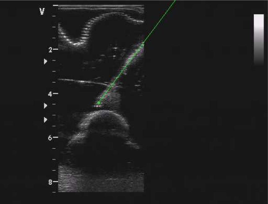
Example of needle tracking during the puncturing
8.4 Situation awareness
Before the ISUR robot starts the needle insertion, the UR5 robot locates the ultrasound probe in a planned pose where the needle should be seen during the puncturing. This nominal pose could be changed at run-time by the surgeon in teleoperated mode if registration errors prevent seeing the needle in the US images. In the present case the rigid registration is quite accurate and so no compensations are needed. However, in the future small translation and rotation of the US probe around the nominal pose will be executed by the robot in an autonomous way to optimize the view of the needle in the US image.
A preliminary step is the offline training of the situation awareness module. US images, together with force sensing and robot kinematic information, were acquired in slightly different needle configurations (i.e., final poses) until the outcome was reliable and robust. A sample of validation is shown in Figure 21. The robot base distance to the target was computed using the ISUR robot kinematics and the path planning information. The tip distance to the target and the angle to the target were estimated by the needle tracking algorithm from the tip position and the needle orientation. Making use of this information, the Bayesian network computed the probability of the reasoning event ‘tumour hit’ as shown on the bottom plot.

Training of the Bayesian network. L1: skin reached, L2: abdomen wall penetrated, L3: needle tracking started, L4: target reached
8.5 Execution
During the puncturing task the ISUR robot must behave in different ways depending on the environment it interacts with. Therefore the robot tool stiffness must change depending on the task phase as described in Section 5. For example, the robot can be compliant in free motion, while it has to be stiff for penetrating the skin and the tumour.
To demonstrate that the system remains stable despite the stiffness changes we also consider different ways of varying the stiffness profile as shown in Figure 22. For example, during the movement of the robot to the position of needle change, the stiffness is augmented gradually (final part of phase A), whereas when the robot is waiting for the needle to be mounted, the stiffness is changed instantly (from phase A to B).

Evolution over time of the values chosen as diagonal elements for the variable part of the stiffness matrix during the autonomous needle insertion. Phases: A Move to start position to needle loading position, B: Wait until the needle is mounted, C: Approach the phantom, D: Penetrate the skin, E: Move to the target point inside the tumour, F Wait until the needle is removed.
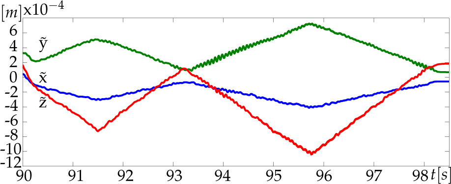
For sake of clarity, the following plots show only the data regarding the translational coordinates x, y and z. Similar results have been obtained for the rotational coordinates.
The desired Cartesian translational positions computed by the admittance controller are reported in Figure 23. As expected, the commanded motion does not diverge (neither oscillate) over time and the system remains stable despite the many changes of stiffness. Figure 24 shows that the tracking error during the insertion of the needle (phase E) is below the acceptable value of 1mm, thanks to the high values of the stiffness in this phase.

Desired Cartesian positions computed by the admittance controller
Tracking error (i.e., difference between the position of the robot end-effector and the desired trajectory) during the approach and insertion phases
During the insertion of the needle the reasoning module was active to monitor the execution of the task. The Bayesian network was processing actual measurements coming from the sensing system and the needle tracking algorithm, and was sending events to the supervisor component within the high-level control architecture.
An initial characterization of the robotic surgical platform revealed that the workspace is sufficient to cover the entire abdominal area of a human, and that positioning precision is acceptable (<1mm), while accuracy was not (up to 7 mm positioning error, compared to 1.04 mm [81], 2 mm [82] or [83]). The latter is currently being improved through a detailed calibration of the platform. During the needle insertion the interaction forces was smaller than 5N satisfying one of the safely requirement.
9. Legal aspects
In this section we analyse the legal barriers to the introduction of robotic surgery devices in medical facilities. No ad hoc regulation exists in the European jurisdiction that is specifically devoted to the topic of autonomous surgery. Two fundamental aspects have been considered: medical liability (related also to medical malpractice in case of robotic devices) and product liability (where ‘product’ is, here, a robotic device or machine). Consequently, the research has focused on the legal consequences deriving from activities of designing/testing/updating the robotic machines and their effective implementation.
Referring to the first aspect, we examined complex issues like ‘informed consent’ and the exception (or exemption) of ‘advancement in scientific knowledge’. Physicians owe several different duties to the patient, including (1) the duty to describe the nature of the treatment or of the examination that the patient should undergo (and alternatives in diagnostic and/or therapeutic methods), (2) the duty to describe possible risks, outcomes hoped for and any possibly predictable negative consequences. Therefore, the patient has to receive all useful and relevant information, so that he/she can knowingly decide whether or not to accept the proposed diagnostic method and whether or not to undergo the therapeutic treatment. A core aspect of our analysis has addressed the question whether, and under what conditions, the lack of specific rules on matters like health services performed with surgical robots makes it possible to apply current rules and principles. Moreover, we have also verified which further (or different) information the patient has the right to obtain when surgical intervention is carried out with the use of a robot machine.
From the side of exception (or exemption) of advancement in scientific knowledge, ‘we have exemptions from liability possibly available to producers of products which cause damages to consumers if producer proves that the state of scientific and technical knowledge at the time when the product was put into circulation was insufficient to identify the product as defective’. We are trying to verify when this exemption can be invoked and for what kind of damages, in the field of robotic surgical machines.
From the second aspect of liability (i.e., product liability), we have considered the relevance of liability in data processing (collection of data, processing and updating with state-of-the-art knowledge) and the relevance of conformity certifications (e.g., ISO certificates) and their effects on liability standards. Trying to find solutions or responses to the above-mentioned issues, we have studied USA regulations in automated products, in particular (although it is a quite different field) the ongoing USA legislative process regarding the lawfulness of producing and commercializing automatic vehicles. In this case, automation is limited to steering, accelerating and braking motor vehicles without human intervention. In both experimental fields (motor vehicles and surgical robots) it is possible to find a common core referring to product liability and liability of users of the product who, in a negligent way, acting or omitting to act, cause a dangerous situation for the safety of someone else.
In the absence of general legislation on robot liability and of well established principles, a great role can be played by contractual regulation. Through contractual regulation we can create disclaimers or liability limitations, so that it is possible to shift the risks related to the use of the surgical robots from one to the other of the subjects involved in the surgical operations. It is worth noting that all these provisions are themselves subject to different regulatory limitations, depending on the law applicable to the contract. On the contrary, in all the cases in which the parties did not agree on a contractual regulation of the most important subjects, the lack of common principles and of uniform existing regulations will impose to verify case-by-case which is the applicable law, by means of the single conflict rules provided by the international private law of the applicable country. In most of the cases this will lead to consistently different solutions, generating uncertainty in the application of law.
10. Conclusions
In this paper we described the design and fabrication of a cognitive robotic platform for executing autonomously simple surgical tasks. We integrated new algorithms to control and monitor the procedure, together with new methods for reasoning during the execution to promptly detect errors and possible unsafe situations. A specific user interface has been designed to continuously provide to the operator the status of the procedure and through which eventually s/he can teleoperate the robots if some event occurs that the system cannot handle autonomously.
We demonstrated that the system is able to plan the intervention for the cryoablation of the kidney tumour, to execute the needle insertion, and to monitor the procedure without any intervention by the operator supervising the surgical action. The experimental validation has been performed on an anatomically accurate US/CT compatible phantom of the human abdomen.
From the viewpoint of the ISUR project, future work aims at improving the robustness of the system, at better integrating the different subsystems, and at enlarging the number of tasks that could be executed autonomously (e.g., cutting and suturing).
From the viewpoint of robotic surgery, in this paper we started to address the following issues related to automation and technology integration that will be more and more important in the near future:
Controlled and increased patient safety. Surgical robots will need automatic control features and monitoring to make further progress in more demanding surgical procedures.
Increased surgical automation. In spite of the progress in computer and robotic assisted surgery (CAS and RAS), automation in the operating room is still far from being a reality. The introduction of more automation will require new procedures and validation methods to support modularity and testing of the devices.
Expanding user and intervention bases. Currently, surgical robot users are surgeons with high technology awareness and who can afford the training and risks associated with the new technologies. Since, in the near future, we should expect a significant growth in the number of surgeons involved in RAS, we need to simplify the use of the robot by adding advanced automatic features.
Safety regulations and standards. Using automation and robotics in the operating room is not just a technological issue but depends on social acceptance, ethical issues and safety regulations and standards. We started an analysis on the ‘legal lag’ between technology and regulations that, if properly driven, will simplify the introduction of these technologies into the operating room in the near future.
The solution of all these challenges will help to pave the way for autonomous and semi-autonomous robotic systems within the operating room.
Footnotes
2
This procedure is at the moment not fully automatized: the intervention of the operator is still necessary.
11. Acknowledgements
The research leading to these results has been partly funded by the European Union Seventh Framework Programme FP7/2007-2013 under grant agreement n. 270396 (Intelligent Surgical Robotics, I-SUR).