
Abstract
This study proposes a novel adaptive fixturing device based on active clamping systems for smart micropositioning of thin-walled precision parts. The modular architecture and the structure flexibility make the system suitable for various industrial applications. The proposed device is realized as a Parallel Kinematic Machine (PKM), opportunely sensorized and controlled, able to perform automatic error-free workpiece clamping procedures, drastically reducing the overall fixturing set-up time. The paper describes the kinematics and dynamics of this mechatronic system. A first campaign of experimental trails has been carried out on the prototype, obtaining promising results.
1. Introduction
The increasing demand of miniaturized items produces the necessity of innovative direct and indirect methods for manufacturing parts. One of the different production techniques for metal components is the micromachining process, which starts from a solid blank block and removes material to realize the final part. This technique is devoted to the realization of complex elements, especially to those that cannot be realized from a planar surface. Micromilling of metal structures with “thin” features represents a major challenge towards broadening the use of this technology in a range of microengineering applications, for example in producing multi-channels, microstructures, housing for mechanical microdevices, and surgical instruments. The main factor that prevents the broader use of micromilling for producing is the stability of the machining operation. By making ribs and webs thinner, their stiffness decreases; this could result in the occurrence of vibrations during machining [1, 2]. As a consequence, the process's accuracy deteriorates. The high frequency vibrations, that could occur during micromilling, result in poor surface quality. Corrections through follow-up finishing operations are not possible or cost-effective due to the features' size. Traditional fixtures, which have been used for many years, are not able to meet the requirements of modern manufacturing processes. The design of a novel adaptive fixturing system implies the merging of many disciplines such as Mechanics, Electronics, and Control. The proposed adaptive fixturing device can lead to performing an automatic error-free workpiece clamping, drastically reducing the overall fixturing set-up time. It also permits recovery of undesired strains induced on the workpiece, and, if necessary, the performance of active vibration control (AVC) in order to limit vibration/chatter effects induced by the cutting. The chatter vibration is not induced by external periodic forces, but the forces causing and maintaining it are generated during the vibratory process itself (the dynamic cutting process).
Machine tool chatter vibrations depend on a self-excitation mechanism in the generation of chip thickness during machining operations [3, 4]. Whatever the source, the vibratory motion affects the cutting process, because the tool and the workpiece are not constantly in contact. Any vibratory motion at the tool tip point between the cutting tool and the workpiece increases the roughness, thus the surface finishing could be unsatisfactory, affecting the quality of the product.
In this case, the proposed system is designed to limit the relative motion between the tool and the workpiece. In practice, the idea is to filter the vibratory motion by directly controlling the position of the table the workpiece is placed on [5].
2. State of the art
The proposed fixturing system for micromilling operations can be classified as a micropositioning system; as the literature describes, several mechatronic devices were also designed with similar aims.
For instance, Verma et al. [6, 7] presented two generations of a novel 6-axis magnetic-levitation (maglev) stage capable of nano-scale positioning. This stage has a very simple and compact structure that is advantageous to meet requirements in the next-generation nano-manufacturing. The 6-axis motion generation is accomplished by the minimum number of actuators and sensors. In the first-generation maglev stage, each vertical actuator consists of a magnet and a coil, and each horizontal actuator consists of two magnets and a coil.
Jung at al. [8–10] suggested a contact-free planar system that realizes the spatial motion of a plate by generating a levitation force and a thrust force at the same plane concurrently. The system utilizes an interaction between the direct drive dc coils of a common shape and the permanent magnets with a coincident polar direction; thus, it is very easy to implement and simple to quantify the magnetic interaction.
Shan et al. [11–13] developed a magnetic suspension stage (MSS) to achieve high-precision three axis motion control. The first version of the MSS [12, 13] utilizes 10 electromagnets; among these, four of them provide vertical suspension force and torques for rotation around the x-axis and y-axis, while the other six electromagnets provide x- and y-axes' actuation force and z-axis torque. The second version of the MSS stage [11] proposed by Kuo et al. is designed to have a travel range of 4 × 4 × 2 mm in translation, 1° × 1° × 2° in rotation, and a total mass of 2.5 kg.
The X Y θ nano-positioning table system proposed by Shinno et al. [14] is symmetrically designed with respect to the driving axes in order to minimize error factors in the table system. The table supported with four stiff porous bearings can be positioned on an aerostatic plane. The table can be fixed at the desired position on the ceramic base by the attracting force with a vacuum pump.
Nomura et al. [15] proposed a 3-DoF (Degree of Freedom) precision stage with an electromagnetic actuator (RE actuator) using a rubber film. The RE actuator is made up of three parts: an upside magnetic pole, an underside electromagnet, and a rubber film between them. Contraction is performed by the magnetic attraction while extension is performed by the reaction force of the rubber film.
Ferreira et al. [16] developed multi-degree of freedom piezoelectric micromotors using both stationary bending modes and travelling wave technology. These devices are based on the conversion, through frictional contact, of bending vibrations sustained in one or several vibrators into rigid body displacements of moving elements, respectively.
Shamoto et al. [17] proposed an ultra-precision 6-axis table developed by employing the principle of “walking drive”. The basic principle of the walking drive is inspired by the walking motion of animals; the table can be fed in X, Y, and θz directions smoothly over long strokes, although the strokes of the actuators themselves are limited to extremely small values. The device consists of a flat plate table and three driving units, each of which is equipped with three driving parts. Each driving part has three piezoelectric actuators (PZTs). The vertical PZTs support the table via the contact blocks, and the feed PZTs drive the contact blocks so that the table is fed in the X and Y directions together with the contact blocks.
Egashira et al. [18] proposed an ultra-precision stage actuated by a non-resonant type ultrasonic motor (NRUSM). The advantages of a NRUSM are high resolution and the lack of magnetic noise generation, due to the DC characteristics of the piezoelectric device, high servo rigidity, and the lack of a need for an additional brake mechanism to direct drive mechanism.
The NRUSM is composed of eight actuators and each actuator is configured of two types of piezoelectric materials (Pb(Zr, Ti)O3), which are induced in dipoles of the expand mode and shear mode and have been stacked (dimension: 3 × 6 × 7 mm). By applying the appropriate control sequence to the stack-type actuators, the infinite feeding becomes possible.
Moser et al. [19] proposed the application of electrostatic glass motors for precise positioning, in order to demonstrate that using the relatively stable charge distribution on glasses induced by an applied electrostatic field, very slow and smooth synchronous propulsion is possible. Kang et al. [20] presented a precision positioning mechanism with nanometre resolution and millimetre travel range.
Two stages are combined with each other by a centre part wound with coil. The structure is the same for each stage; it is composed by a flexure (leaf-spring) guide whose type is a double compound linear spring and a VCM (voice-coil motor) actuator.
Ryu et al. [21] developed a micro-motion stage with three degrees-of-freedom. The X Y θ stage uses three piezoelectric actuators and a monolithic flexure hinge mechanism that is designed to provide large θ motion. The monolithic flexure hinge mechanism is utilized as a joint mechanism between output body (workpiece holder) and actuators. Such mechanisms provide almost no backlash or stick-slip friction and assure/allow smooth, continuous displacement positioning.
Chang et al. [22] developed a three degree-of-freedom micropositioner for deep ultraviolet lithography applications. This micropositioner uses symmetrical geometry to achieve nanometre resolution, high stiffness, large output force, and extremely low crosstalk interference.
Gao et al. [23] developed a micro-fixturing capable of producing micro-motions in six degrees of freedom, based on the design of a single-degree-of-freedom piezoelectric translator composed of a piezoelectric stack, a monolithic leaf spring and a preload mechanism.
The nano-fixturing for quasi-static manipulation proposed by Culpepper et al. [24] is based on a HexFlex™ mechanism actuated by electromagnetic actuators. The design incorporates lever arms, to which in-plane and out-of-plane forces may be applied.
Choi et al [25] proposed a different configuration of a nano-positioning stage driven by piezoelectric elements. The stage has the structure of a monolithic nested-loop type moving plates, in which each moving plate is guided by two four-link mechanisms. The four-link mechanism plays the role of motion guidance for translation as well as transmission of a preload to the piezoelectric element. The four hinges of the four-link mechanism are implemented by four round-notched flexure hinges. Due to the nested-loop type structure, the moving plates are actuated independently of each other by piezoelectric elements so that the stage can avoid coupled interference motions.
Yi et al. [26] proposed a 3-DoF parallel mechanism consisting of a platform and three chains, each of which has three flexure hinges. This mechanism employs flexure hinges at all joints and the joints are actuated by piezoactuators. The three chains are 120 degrees apart; this symmetric structure reduces the effect of the temperature gradient and disturbance.
The XY flexure design proposed by Awtar et al. [27] is characterized by a large range of motion and substantially small error-motions. The design is based on a constraint arrangement that is realized by utilizing the double parallelogram flexure module. The constraint arrangement includes four basic rigid stages: ground, motion stage, and intermediate stages.
Wu and Zhou [28] presented a novel mechanism to obtain X Y θ motions in a plane with only one actuator, in order to make the X Y θ mechanism smaller and more compact.
The micro-positioning device proposed by Liu et al. [29] for the automatic assembly of small components uses the impact force of piezoelectric (PZT)-driven thin wires. The printing element consists of PZT actuators that use the longitudinal effect to actuate a thin wire to impact the target object to be positioned. The impact action, or hammering, brings about a change in the torque, resulting in the motion of the target object. This type of high-speed wire is commonly referred to as “flying wire”.
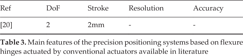
In Tables 1–4 the main features of the precision positioning systems are summarized, as available in the literature.
Main features of the precision positioning systems not based on flexure hinges actuated by conventional actuators available in literature

Main features of the precision positioning systems not based on flexure hinges actuated by smart actuators available in literature

Main features of the precision positioning systems based on flexure hinges actuated by conventional actuators available in literature
Main features of the precision positioning systems based on flexure hinges actuated by smart actuators available in literature

The state of the art [30–32] emphasizes that a PZT actuation element integrated with a compliant mechanism is the most promising technology which can achieve the best compromise between high actuators' stroke and high accuracy performances (sub-nanometre) in a broad motion range (<1μm; 1˜100μm; 100˜1000μm; >1000μm). Moreover, the PZT actuation element and the compliant mechanism are both economically viable.
Although the literature presents various piezoelectric devices, the vibration and static force compensation systems based on such types of actuators are not so common, especially in micromilling applications. In view of these considerations, an innovative adaptive fixturing device for smart micropositioning is introduced.
3. The Adaptive Fixturing System
The proposed innovative and adaptive fixturing device is essentially based on three clamps, each of them mounted on an actuation element (Fig. 1). Beyond those three clamping modules, the system also integrates a smart actuator and eddy current sensors, suitable to automatically recover workpiece positioning errors or distortions. A dedicated closed loop control system has in fact been implemented, based on active/dynamic clamping forces sensing (Fig. 2).

The proposed PKM fixturing system, (Maximum Volume as 6 dm3)

The fixturing device
In more detail, the single module (Fig. 2) is based on the following main components:
Clamps: needed to fix the workpiece, and which have relative freedom to move with respect to one another in the vertical direction;
Axial rod: the clamps are fixed to the rod, while the rod is free to move vertically with respect to the rest of the module;
Flexure hinges: mechanical decouplers for shear forces and torques, in order to prevent the piezoactuator cracking;
Axial chuck and axial screw nut: mechanical devices needed to clamp the rod to the flexures;
Axial Spring: the spring pushes the rod upward, up to its maximum allowed stroke. Since this element should not oppose resistance when the workpiece is positioned [33, 34], a low stiffness spring has been chosen.
The adaptive fixturing consists of the following clamping sequence (Fig. 3):

Clamping sequence: from the left, the approaching, the clamping, and the blocking phases
Approaching phase: pliers approach the workpiece, opportunely guided but with no axial constraint.
Clamping phase: pliers clamp the workpiece, adapting themselves to the piece, and avoiding in this way undesired constraints.
Blocking phase: pliers' axial degree of freedom is blocked, in order to constrain the workpiece with respect to the fixture.
Each actuation element, properly constrained to the system, presents a single DoF along the clamping direction. The system should implicitly recover unwanted strains induced on the workpiece by the clamping procedure, since in the case of deformations the embedded actuator (Fig. 3) may restore the undeformed configuration.
More precisely, every clamp is constrained to an adjustable vertical rod, and is therefore moveable along the same direction with respect to the rest of the module; each clamp, however, also remains free to move with respect to the others. In order to clamp a workpiece, the relative movement of the clamps is first constrained to the workpiece, so that the clamps, the moveable rod, and the workpiece constitute a single body.
The rod is not constrained to the rest of the clamping module, thus it is free to move vertically and the workpiece does not experience any deformation. Then, the rod is fixed to the flexures. By simply tightening the nut of the axial screw (Fig. 3, on the right), the user deforms the axial chuck until it completely constrains the moveable rod. Now the workpiece is fully constrained, and the piezoactuator is able to exert its action: in other words, the fixturing device has become an active system.
Several aspects have been analysed in order to assure the most suitable design choices; for instance, a dimensional trade-off analysis has been performed, optimizing the most interesting parameters (max. strokes vs. size, vs. stiffness, vs. bandwidth) to select the proper actuators and guiding (frictionless) system.
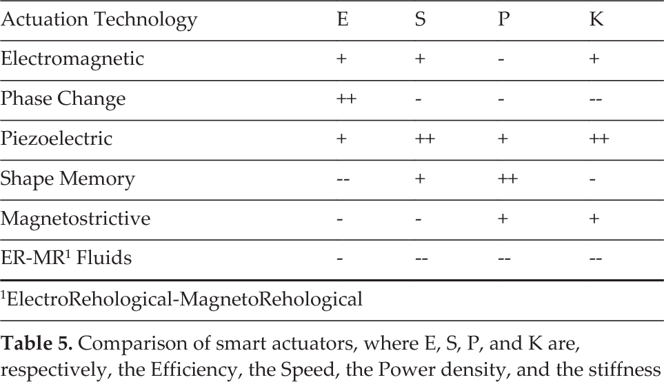
Indeed, particular attention has been paid to the actuator selection, as a key element of the whole system. Many actuators are claimed to be smart [35–38], and each of them offers different features (Tab. 5), where different actuation technology, electromagnetic phase change [39, 40], piezoelectric [41, 42], shape memory [38, 43], magnetostrictive [44, 45], electrorheological and magnetorheological devices [46, 47], are compared. Among the most interesting features for this application are efficiency, bandwidth, power density, mechanical stiffness, and compactness. The design analysis [2, 48–50] suggested the piezoelectric actuator as the most suitable solution.
Comparison of smart actuators, where E, S, P, and K are, respectively, the Efficiency, the Speed, the Power density, and the stiffness
Conversely, the main system requirements are modularity and flexibility, since the fixturing device should be able to clamp various workpieces in different clamping configurations, always fulfilling the desired mechanical requirements, e.g., both providing the required stroke and force, and recovering possible distortion errors induced on the workpiece during the clamping. The new device is hence required to reach, engage (and disengage) clamping points with an “active” behaviour, in order to satisfy possible different clamping heights of the workpiece. Since the piezoactuator can only provide a limited stroke, a hybrid telescopic clamping mechanism has been also designed and realized: this mechanism enables a maximum stroke of 40μm (resolution accuracy ± 1μm), obtained as the PZT elongation, plus 10 μm stroke allowed by the mechanical connection between clamp module and actuator.
Finally, every active clamping module integrates a strain gauge sensor, a force sensor, and a contact-free eddy current sensor, aimed to measure the clamping point position; this parameter feeds a closed loop control system, implemented to automatically recover the possible deformation error generated in the clamping phase.
Beyond the limited stroke, piezoelectric actuators present another awkward issue in their incapacity to bear shear forces and torques. In order to preserve the piezoactuator's functionality, a proper flexure hinge has been positioned between the frame and the piezoelectric element itself, assuring the decoupling of potentially dangerous applied loads. This flexure hinge is realized as a single stainless steel part and is basically composed of two circular thin plates and a central cylindrical element. Six screws assure the connection of the hinge, constrained to the piezoelectric actuator, to the frame, allowing the transmission of both vertical loads from/to the actuator and radial torques to the frame, while providing high axial and lateral stiffness.
Finally, one of the main disadvantages that affect the existing adaptive fixturing devices is their huge size, which makes them unwieldy and difficult to be integrated in different grinding machines. On the other hand, on most occasions big dimensions imply a low bandwidth. The proposed device is, on the contrary, small, presents high cut off frequencies, and can therefore find more applications in different fixtures.
4. Kinematic Model
Although the kinematic behaviour of the system could be intuitively understood, the modelling process of the connection between the central platform and clamping modules requires particular care because of the hyperstatic condition herein present.
Fig. 4 depicts this critical aspect with a simplified kinematic chain: the platform, modelled as an ideal link, is connected to only two of the three active clamping modules thanks to spherical joints. The clamping modules, constrained to the ground, have been functionally modelled as the ideal pistons 1 and 2. Forcing the actuators to assume the same vertical coordinate (i.e.. H1 = H2), the platform results horizontal. Whether an incremental dH is then added to just one of the pistons, for instance to the second one, the B point tends to move towards B‘, while the coupler link follows the variation by ideally rotating about A, hence forcing B to reach B″. Since the platform is rigid and not deformable, the α rotation transforms dH into an increment dl along the AB″ direction, introducing an hyperstatic condition into the kinematic chain.

A simplified kinematic chain, composed of two pistons and a coupler link; the ideal structure presents negligible masses
This structure can be easily seen as a simplified model of each couple of pistons of the device: as a consequence, the fixturing system presents three hyperstatic critical conditions. These critical elements have been solved in the modellization adding a coincident fictitious slider constraint in each of the spherical joints linking the platform to each piston.
In this way, a fictitious DoF has been introduced in the platform, i.e., a translation along its own plane, to justify the microdisplacements which in the real structure are assured by the presence of flexural hinges, properly located between each piston and the mobile platform.
According to these considerations, Fig. 5 shows the final equivalent simplified model, and the basic nomenclature adopted for the kinematic and dynamic investigation of the fixturing device.

Functional scheme of the fixturing device: B is the base; P and P are prismatic joints; and S is a spherical joint. T, L, C and G are better explained by Fig. 7

Referring to Fig. 5, the parallel PKM can be easily schematized as a 3-PSP structure, composed of three kinematic chains with an active prismatic joint P, a passive spherical joint S, and a passive prismatic joint P. According to the Grubler-Kuzbach criterion, this mechanical system reveals 6r-5m, or more precisely, 6times13-5times15=3 DoF. Since these DoF are well disposed, the system exhibits three DoF during the motion; for this reason, the device can be seen as a tripod mobilized by three pistons (our piezoelectric actuators).
The displacement realized by the generic point of the platform, with respect to the fixed reference frame centred in O, shown in Fig. 7, depends on the positions of the three lengths of the pistons qi (with i = 1; 2; 3 hereafter, unless otherwise indicated), but is also related to hmin, defined as the constant value physically reachable by each actuation module when the pistons are at their minimum possible value.
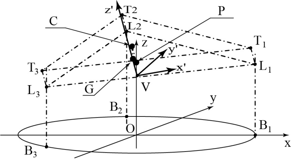
Geometrical description: a simplified scheme
Equation (1) describes the relation between the height hi, reached by ith active module, and the imposed piezoactuator stroke.

The presence of the slider constraints complicates the formalization of the solution to the direct kinematic problem of the platform.
The three actuators allow the device the same kind of movement which a single equivalent piston, located in the Centre of Gravity (CoG) of their base and parallel to them, would introduce (see P point in Fig.5). The identification of the quote of the plane containing the platform can be hence easily performed evaluating a single parameter: the mean value of the quotes of the actuation modules.
On the contrary, the computation of the platform pose results complex, since its CoG moves within the plane, according to the fictitious DoF.
Now, let us call C the projection of the P point on the upper surface of the platform; this plane is obviously parallel to the one identified by the quotes of three actuation modules. Under these hypotheses, a single reference frame, located in C and rotating according to the plane of the upper platform surface, can totally describe the system pose, provided that the best couple of angles is chosen for the orientation description. As a matter of fact, two angles, by describing the platform orientation, allow the identification of an improper sheaf of planes; among them, the quote of C isolates the relevant one.
In conclusion, the fixturing device pose can be exhaustively described thanks to three independent parameters, arbitrarily chosen: a translation parameter and two angles have been assumed, here.
The goal of the kinematic analysis is the determination of the relations between the column vectors S and Q. The first vector (S) contains the pose of the mobile platform, as the height of the G point (the projection of the platform CoG on the upper plane of the platform itself), and the two angles defining the space orientation of the system. On the contrary, the information dealing with the actuation is related to the second vector (Q): its elements are the three qi lengths of the pistons.
In order to simplify the analytical evaluation of the kinematic solution of the system, the Tilt and Torsion (T&T) angular notation has been implemented.
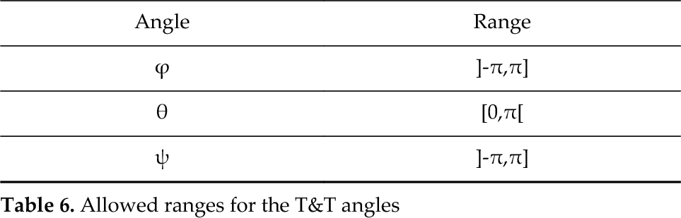
According to this notation, the T&T angles are equivalent to the Euler angles, unless ψ (see Fig. 6) has been replaced by σ-ϕ. Since any orientation of a body in the space could be expressed thanks to at least two triplets of angles, the ranges of the T&T angles need to be carefully chosen in order to avoid potential ambiguities; Tab. 6 collects the set of the allowed values in our instance.
Allowed ranges for the T&T angles
Under these considerations, a significant simplification in the analysis of fixturing structure can be derived. The proposed device can be classified as a no–torsion device: as a matter of fact, this mechanism presents zero torsion for all configurations. Moreover, the kinematics have been developed thanks to a relatively simple and intuitive algebraic analysis.
Referring to Fig. 7, let us define
As a matter of fact, after simplification none of the identified relations contains z as an independent coordinate; in order to obtain a solution for x and y, the condition of linear dependence among the three constraint equations has therefore to be imposed. One of the most common strategies to force the linear dependence among more relations is the definition of the proper coefficient matrix of the equations: in order for them to be linearly dependent, the matrix determinant should be equal to zero. Relation (3) shows the obtained condition in our instance.


Of course, this relation, although necessary, is not a sufficient condition; through the analysis of the Equation (3) and its relation with the system (2), the singular conditions of this kinematic structure can be identified, as the following section will show.
Finally, even if the system (2) describes a simplified structure, involving the position of the V point instead of G, the kinematics can be considered to be totally defined as well, since the identified procedure allows us to determine, as the relation (4) presents, the horizontal offset of V from the central axis in terms of the T&T angles, whose minimum and maximum values are described in the equations (4).

5. The fixturing device Workspace
The fixturing device Workspace (WS) can be evaluated thanks to the condition (3) and the system (2). Focusing on those relations and on the physical meaning of the T&T angles, allows the WS and the possible singularity conditions of the structure to be identified, as synthesized in Tab. 7.
Evaluation of the fixturing WS, where ci and si are, respectively, cos(i) and sin(i)

Referring to this table, a first observation is related to the conditions θ = ±π/2: although no solution of the system (2) would be here defined, since in these cases the mobile platform could not be assembled, these configurations can be neglected in order to evaluate the fixturing WS. A different situation follows from the condition of θ = π: in this instance the mobile platform is upside down and its orientation is defined by the quantity (2ϕ - σ). The V point moves, in this configuration, along a horizontal circumference, centred in the z-axis and with the unit radius. It should also be noted that for a complete counter–clockwise tour of the point V along this circumference, the mobile platform covers only half a turn (in the same direction). Finally, analysing the last part of the table, it can be noted how the same solution of the system (2) could be obtained for both the conditions σ = 0 and σ = π. Fortunately, the mutual exclusion between these two modes of operation is assured, since the switching would require the disassembling of the mechanism.
6. The Dynamic Analysis
Kinematic study and Dynamic analysis of the system has been developed almost simultaneously. The core of the dynamic analysis is the model of each active fixturing module. In order to obtain highly dynamic performances, the model should be as simple, complete, and effective as possible. Some preliminary experimental data, and FEM analyses in MSC Nastran environment, suggested to us that we should develop a simplified functional model of the system.
For instance, the vertical platform stiffness (600·103 N/mm) should be rigorously modelled thanks to three springs, each of them connected to one of the clamping modules. Moreover, every active module should be modelled as a spring as well, characterized by a stiffness of 300·103 N/mm.
Nevertheless, supported by the data presented in Table 8, a single active spring (stiffness 200·103 N/mm) has been adopted to model both the elements, as the resulting equivalent model in Fig. 8 presents. However, the damping ratio of every clamping module has been initially neglected according to the results of an Instrumented Hammer test.
Analytical and FE model: comparison of the first three eigenfrequencies of the first controllable modes (I — rotation around the x-axis, II — rotation around the y-axis, III — translation along the z-axis)


Equivalent dynamic model
Referring to Fig. 8, the basic conventions about rotation angles' order and reference frame nomenclature, the traditional Euler conventions have been adopted; the column vector
According to the D'Alembert method, the dynamic behaviour of a system can be totally described thanks to three equilibrium equations arbitrarily chosen, providing their linear independence. These relations need to be contemporaneously verified, and can therefore be collected into a common system, hereafter referred to as the characteristic equation system. Assuming then to redefine column vector
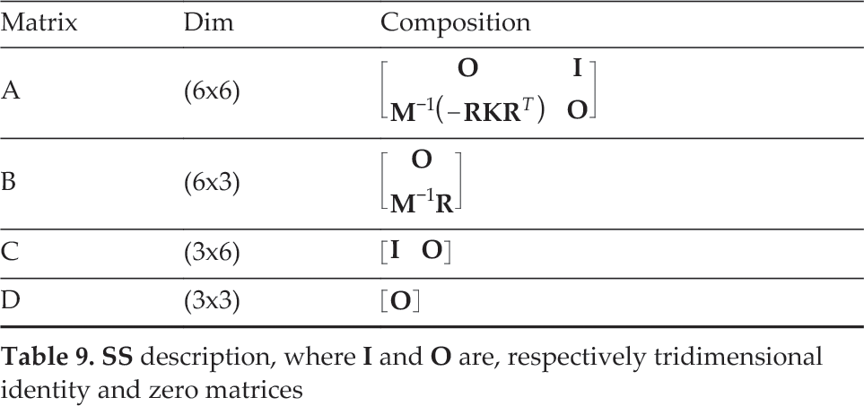


Once the SS matrices have been identified, the
7. Simulation results
Traditionally, fixture systems are designed for dedicated use, which essentially means that they cannot be adapted to hold other parts. Novel fixturing concepts are developed in order to prevent two major drawbacks: poor accuracy, and long set-up times. In that way, the sensors and actuators, integrated in an intelligent fixturing system, allow the automatic and precise reconfiguration of the fixturing elements. According to the literature, the main process variables influencing the control in active fixturing processes are the fixture displacements, and the reaction forces at the contacts where the workpiece is fixed [4].
In order to simplify the analysis process, the proposed active fixturing system has been schematized into the following subsystems: the workpiece or part, the part-fixture contact interface, passive fixture elements, the actuated clamp, sensors, and the controller.
The new fixture design should drive reduced set-up times and an increased locating performance (as the positioning and aligning of the workpiece during the setup machining process), as well as minimal distortion due to clamping forces. In order to obtain a quick but effective establishment of the demonstrator, the part has been located in the xy-plane and three auxiliary datum-points have been used.
The mechanical clamps provide forces in the z-direction and can additionally reposition the workpiece during the part-fixture set-up, using the actuator displacements.
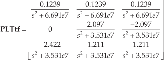
A preliminary linearized model has been developed, neglecting both the hysteresis of the piezoelectric actuation and nonlinearities that occur over large displacements.
Fig. 9 shows the architecture of the closed-loop control system implemented for each active clamp in SimulinkRT and DSpace environments.

Hardware in the loop (HIL) Architecture Fixturing system validation
The system architecture presents three control inputs (voltage signals) and the reaction displacements at the three datum-points as outputs.
The controller implements PI logic: the derivative contribution can be neglected thanks to the quick response assured by the piezoelectric actuation. For the PI tuning, the predefined auto-tuning strategy implemented in the DSpace system has been adopted.
Once the actuators' output is defined as the controlled system output (collocated control), the DSpace environment is also allowed to implement an automatic “nearly decoupled” control strategy: indeed, single-input single-output (SISO) feedback loops can be established, in which clamps do not interact with one another. The process cannot be considered completely decoupled since the model simplifications (e.g., actuators' linearization) would introduce errors in the control of the physical device: those errors are, however, negligible for our small displacements.
Clamps control loops are established by measuring the displacement using a contact-free eddy current sensor at clamping-points. An inductive proximity measuring system is a low-cost precision sensing strategy, offering excellent resolution and repeatability for accurate static as well as dynamic measurements (Movement detected > 3kHz; Output saturation 45μs; Resolution accuracy: 0.1μm). Measured displacements are compared with the reference values defined for clamps; the controller reads those error signals and properly steers the actuators until the desired outputs at the clamps are reached. Since the clamps are considerably stiffer than the workpiece, they can be modelled as spring-dashpot elements that are connected to single nodes in the model reduction process.
The friction between the clamps and the workpiece guarantees adequate constraint in x- and y-directions.
The damping ratio has been estimated through an experimental test (Instrumented Hammer test) as 5÷8%. The overall model has been inserted into a state-space formulation and the differential equations that describe the transfer functions of the system have been rewritten into a first order system and added to the part-fixture model. Since the resulting machining process quality is related to the overall deformation of the part, the reaction displacements at the clamps can be seen as measures for the overall deformation.
8. Experimental results
Once the numerical simulation implemented in SimulinkRT and DSpace environments confirmed the working principle, experimental tests on the physical test bench were carried out.
In the first validation campaign, the fixturing device was statically loaded, up to its worst working condition — a 40μm displacement (Fig.10): in fact, an incorrect clamping procedure may result in a static disturbance force at the clamping points.

Displacement of the piezoactuators when the clamping point C1 is statically loaded up to 40μm
The main goal of this preliminary test is, therefore, to point out the static behaviour of the system, and validate the control ability to recover the undeformed configuration, acting on the three clamping modules: the implemented control system demonstrated a settling time lower than 18ms.
A further experimental test aimed to characterize one of the most awkward issues in the dynamics of piezoelectric actuators: the hysteresis. The knowledge of the hysteresis phenomenon is a key aspect in high performance dynamic processes; the realized tests were focused on the identification of the hysteresis curves of every piezoelectric actuator. Fig. 11 collects the two most significant graphs (the two actuators presenting the minimum and maximum hysteresis value).
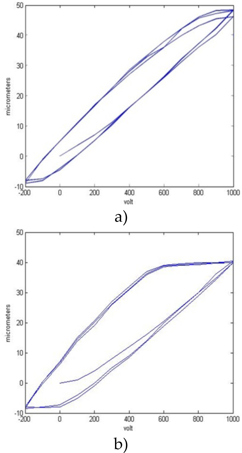
The two most significant hysteresis curves of the actuators: a) minimum hysteresis value, and b) maximum hystersis value
The hysteresis outcomes highlight that the model and signal management needs to be improved in order to achieve dynamic performance. The maximal stroke achievable by each active clamping device is about 40 micron and this is in accordance with the requirements for this application. The experimental stiffness values (axial and radial) differ about 10% from the numerical values, thus confirming the validity of the FE model.
Finally, a low frequency control test (from 1 to 8 Hz) has been performed. The workpiece is initially positioned upon the three data points so that results are aligned in vertical direction and all sensors' measures can be consequently reset to zero. The workpiece is then clamped and a positioning error is imposed (disturbance: 20μm stroke) through the application of a vertical asymmetric force on it (800 N).
The resultant workpiece misalignment is detected by the sensors. When the PI control is switched-on, this error is recovered by the active clamps and the initial alignment is restored. The experimental recovering curve of one clamp is shown in Fig. 12 (blue line).
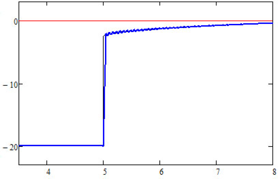
Numerical result (black) compared with experimental result (blue), with a zero reference (red), where the displacement [μm] is shown in the vertical axis and the time [s] is shown on the horizontal axis
The controller is switched-on after five seconds and the recovery time is less than 20μs according to the expected target. The first ramp is due to the proportional effect of the PI, while the following slow error reduction is due to the integral contribution.
These simple tests prove to be quite effective and comprehensive to validate the numerical simulations and the working principle of the proposed system. In fact, the contribution to the motion eventually introduced by additional shear loads would be completely nullified by the dedicated flexure hinges.
9. Conclusions
An adaptive fixturing system, based on clamping modules and for ultra-high precision micropositioning has been designed, developed, and prototyped. The system concept and kinematic analysis has been initially presented and explained. The proposed system is able to reconfigure its fixtures for different workpiece sizes, preserving high performances in terms of accuracy, stiffness, and compactness.
In particular, it can perform an automatic error-free workpiece clamping, drastically reducing the overall fixturing set-up time, besides recovering unwanted strains induced on the workpiece itself.
The functional concept has been verified both with numerical mechatronic simulations and experimental tests. The very promising results prove not only the effectiveness of the innovative system, but also its proper manufacture, with particular attention to structure stiffness and ultra-precise micromovements.
Finally, the system potentially allows the performance of active vibration control in order to limit vibration/chatter effects induced by the machining; a further outcome of this study will therefore be to test and perform the proposed system in highly dynamic conditions, such as in real machining processes.
The proposed fixturing device can represent an important improvement in micromachining of thin-walled parts and could open interesting perspectives for actual and future industrial applications.
Footnotes
10. Acknowledgements
The work developed in this report is partially funded by the EU Project IP 214013 titled Integ-Micro. The authors wish to thank the European Commission and all the partners of the consortium. A final thank you to the anonymous reviewers and to the editor of this article for the interesting comments.