
Abstract
Fixtures are critical part of both traditional and modern manufacturing operations. The time allocated to the design and manufacture of these components significantly impacts production cycle time and can improve the quality of current and future products, and therefore, significant consideration is required to design fixture and their applications in manufacturing. In this article, design of an automatic modular fixture modeling system is proposed for prismatic components. The proposed system consists of fixture planning, fixture layout, and fixture assembly modules. The process and setup plans are used as input into the system. A rule-based system is developed to assign suitable locating scheme to locate and clamp datum for fixture planning phase. The search strategy is designed to select the locating and clamping points based on geometric and functional constraints. The final fixture assembly is achieved using standard fixture components and CATVBA editor using CATIA V5 as the platform. The graphical fixture database is constructed using commercial fixture components from manufacturers such as Fixture Works and Carrlane. The proposed methodology is successfully validated with multiple case studies.
Introduction
Fixtures are used for locating, holding, and supporting a work-piece during manufacturing operations. Fixtures are essential elements of production processes as they are required in most of the automated manufacturing, inspection, and assembly operations. Fixtures must correctly locate a work-piece in a given orientation with respect to a cutting tool or measuring device, or with respect to another component, as, for instance, in assembly or welding. Such location must be invariant to clamp and secure the work-piece in the desired location for the particular processing operation. 1
Modular fixturing systems use a group of individual components, which are assembled on a base-plate to fit the work-piece which requires fixturing. Modular fixturing systems are typically used for prototype tooling, short-run production tools for limited part quantities, or as a backup work-holder to replace dedicated tooling which may require service or repair. Some advantages of using modular fixture systems include flexibility, reduction in fixture construction time, and the reduction of storage space and fixturing components. By using standard fixturing components, the fixture can be assembled on average of 20% of the time as compared to the dedicated fixtures. Modifications also take considerably less time. There are two types of modular fixture systems: T-slot based and dowel-pin based. 2 The overall stiffness of the dowel-pin modular fixture system is higher than that of the T-slot system. Moreover, the dowel-pin system is easy to manufacture and provide precise location of the part.
In this article, the process and setup planning data are used as input to the fixture design system. The system consists of fixture planning, fixture layout, and fixture assembly modules. The rule-based approach is used to generate the fixture planning data. The fixture layout module is obtained by the designed search strategy based on fixturing rules, geometrical and dimensional constraints, and graphical fixture database. The modular fixture assembly is done using CATVBA file. Visual C++ is used to integrate and automate the fixture design modules and graphical database.
The article is organized as follows. Section “Literature review” includes a comprehensive state-of-the-art literature review in fixture design. The proposed methodology is then discussed in section “Proposed methodology,” and section “Implementation and results” demonstrates the implementation steps using a sample case study. Finally, the conclusion is discussed in section “Conclusion.”
Literature review
Fixture design process begins from fixture planning phase. This step consists of the selection of the fixture type, part complexity, orientation of work-piece, and selection of locating and clamping faces. Fixture layout determines the position and types of locating, supporting, and clamping devices. In fixture assembly, the fixture body design is completed by developing the fixture layout with designed elements. 3 Several techniques and procedures are proposed in the literature for designing fixtures, although a selected number of these methods are discussed in this article.
Knowledge-based engineering methods are used to develop the knowledge infrastructure for geometrical information, machining process, fixture design elements, and fixture resources, used for all phases of fixture design steps coupled with rules to plan the process for machining fixtures. Ríos et al. 4 developed a knowledge-based system for fixturing of high-speed milling. Alarcon et al.5,6 presented a functional design approach in which the functional requirements and constraints are considered as an input to the fixture design process. The fixture design solution is then created in two levels: functional and detailed. The functional level is based on fixture functional elements, and the detailed one is based on fixture commercial elements.
Many geometrical and analytical methods are implemented based on the literature for modular fixture design and verification. Ma et al., 7 presented an analytical approach for automated fixture planning based on work-piece geometry and operational information. The surface accessibility, accuracy, and fixturing stability were the major parameters used in the design of the fixture planning system. Wu et al.8,9 developed a geometrical analysis approach for automated modular fixture planning. The proposed method was used to determine the fixture surfaces and points. The system analyzed the fixture accessibility, accuracy and clamp planning. Zheng and Qian 10 developed a set of algorithms used for automatically selecting the optimal fixture points on the base-plates and accurately locate and firmly clamp the object. Methods for measuring the location error and adjusting the fixture points to improve the localization accuracy are also presented.
Case-based reasoning (CBR) methods are a variant fixture planning. CBR methods require the results from the previous cases that are used and applied for the development of the new system. The most important elements in the CBR process include four steps: retrieval, reuse, revise, and retain. Li et al. 11 presented a case-based agile fixture design for re-configurability, re-scalability, and re-usability. Liqing 12 and Liqing and Kumar 13 developed an Internet-enabled computer-aided fixture design using distributed CBR approach. Case representation for fixture design includes part representation, fixture representation and setup representation. These were coded in eXtensible Markup Language (XML) using Unified Modeling Language (UML) notations. A feature-based similarity measure was used for case indexing and case retrieval in this system. The two major considerations used are geometric shape and material. Wang and Rong 14 presented a CBR approach for welding fixture design using the available design cases to quickly propose a fixture solution.
Virtual Reality (VR) is a technology to simulate the real world in a virtual computer-generated environment. Qiang 15 developed a VR Fixture Design & Assembly System (VFDAS) for fixture design. The system allows fixture designers to complete the overall design process for modular fixtures within the Virtual Environment (VE), including fixture element selection, fixture layout design, assembly, analysis, and other related tasks. Gaoliang et al. 16 presented a VR-based system for interactive modular fixture configuration design. The system used a multi-view-based modular fixture assembly model to assist in information representation and management. The multi-view model exploited the advantages of hierarchical structure model and assembly relationship model.
Boerma and Kals 17 developed a computer-aided system for the automatic generation of setups and fixture design of prismatic parts. Fuh et al. 18 developed an integrated system using CADLOG for the generation of manufacturing plans after the part design has been completed. Kumar et al. 19 developed an automatic fixture design (AFD) system, so that the fixturing points were planned in compliance with the fixturing principles that are formulated as a set of heuristics rules to generate candidate list of points, and then select the exact points from the list. Machining interference detection is accomplished by the cutter swept volume approach. Kale and Pande 20 proposed an algorithm for determining the locating and clamping points for automatic generation of fixture layout plan using the 4-2-1 locating scheme. Mervyn et al. 21 presented an Internet-enabled fixture design system. The system uses XML file format for information and knowledge transfer between various computer-aided manufacturing elements within the system. Babu et al. 22 used AutoLisp for developing an automatic fixture planning model based on two-dimensional (2D) drawing data using 3-2-1 configuration, considering geometrical and dimensional constraints.
In this article, an object-oriented modeling approach is used to develop an integrated and automated fixture modeling process using specific search strategy. Based on the literature, a three-dimensional (3D) fixture design solution based on modularity concept is required. The work shown in this article is only for block-shaped prismatic parts.
Proposed methodology
The methodology presented is divided into three modules: fixture planning, fixture layout, and fixture assembly modules. The fixture planning module determines the locating scheme and the data necessary for locating and clamping of the prismatic part. The fixture layout module determines the best locating scheme and feasible locating and clamping datum. A search strategy is developed for the selection of modular fixture components and identification of locating and clamping positions for the final fixture assembly. The strategy established is based on analyzing the fixturing rules, part geometries and dimensional constraints using the modular fixture database. The final fixture assembly is developed using CATIA V5 and CATVBA Programs. The CATVBA file automatically extracts the fixture layout data within the CATIA V5 file for fixture assembly. The graphical database is obtained from available commercial fixture components’ manufacturers like Fixture Works and Carrlane. Visual C++ is used to integrate and automate various fixture design functions within the modules, CATVBA and graphical database.
Fixture planning module
The fixture planning phase determines the best locating scheme, locating and clamping datum for each setup required for part processing. The block-shaped prismatic part has six orientations with respect to the x, y, and z axes. These are named as XY, top and bottom; ZX, front and back; and YZ, left and right (Figure 1).
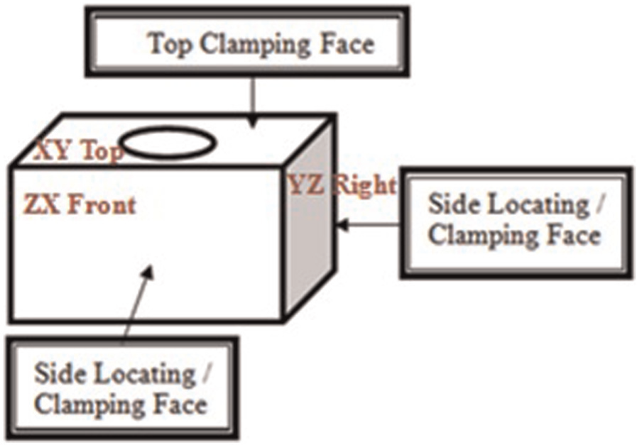
Candidate locating and clamping faces.
Locating scheme
A free solid body work-piece has six degrees of freedom, three linear displacements along the mutually orthogonal coordinate axes, and three angular displacements with respect to the same axes. During a setup, it is necessary to restrict certain degrees of freedom so as to locate and orient feature surfaces with respect to the cutting tools. For prismatic-shape work-pieces, the most common locating scheme is 3-2-1 that restricts all six degrees of freedom. Determination of locating scheme could include many variations due to shape of the part, primary datum surface, and cutting tool path trajectory and constraints.
Considering the above conditions, the rules are formulated to determine the correct locating scheme for each type of work-piece orientation. An example of the developed rule is as follows:
If work-piece is small cube;
Primary datum is XY bottom;
Cutting tool is penetrating in the primary datum surface;
Then 3-2-1 locating scheme is feasible.
Locating and clamping faces
The potential locating faces should be along three mutually perpendicular planes and part clamping should be positioned to provide the required clamping force and secure the work-piece. There are two common clamping methods: overhead and side clamps. The overhead clamp applies a force perpendicular to the fixture base-plate and the side clamp applies a force parallel to the fixture base-plate. Overhead clamping method is used widely in industry due to higher locating accuracy; a fixture configuration with overhead clamps is considered preferentially for the proposed methodology. 23
The primary locating surface is always the datum surface of the work-piece. It depends on the work-piece orientation with reference to the cutting path of the machine tool. In fixture planning, surfaces with high-accuracy grades are set as locating surfaces in order to minimize the machining errors and achieve the required tolerances of the machining features. 7
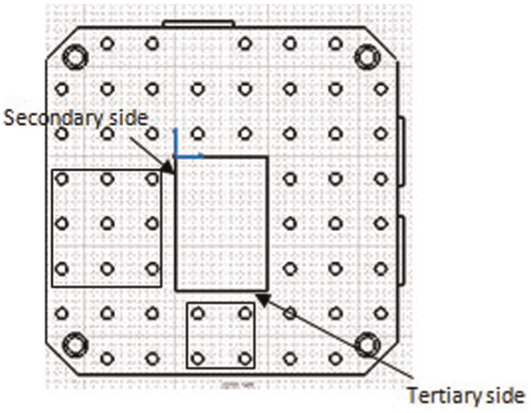
The larger side of locating surfaces is set as the secondary datum surface and two locators will be used for this surface. Finally, the smaller side is set as the tertiary locating surface with only one locator based on the 3-2-1 rule. If more than one faces are available for secondary or tertiary location, then the face with larger surface area is selected. The raw material is assumed to be pre-machined with fine roughness value. This will ensure the minimization of locating errors. The set of rules used for selecting secondary and tertiary locating faces are as follows:
If a feature f1 is to be machined in this setup And F1 is the side location surface of f1 And
F2 is the primary datum surface and
F1 is perpendicular to F2, and F1 is machined and has fine roughness
F1 is suitable for the secondary locating surface
If a feature f1 is to be machined in this setup And F1 is the side locating surface of f1 and
F2 is the primary reference surface, F3 is the secondary locating surface
and F1 is perpendicular to F2 and F3, and F1 is machined and has fine roughness
F1 is suitable for the tertiary locating surface
Fixture layout module
The fixture layout process should satisfy the following fixturing requirements:
An accurate locating method should be adopted.
There should be no interference between the modular fixture components and machine cutter.
Holding the work-piece rigidly to prevent any deflection during machining.
The minimum number of clamps are selected to avoid any redundancy. If all the locating requirements are satisfied, only two clamps are required to secure the part against three supports using the 3-2-1 locating scheme. This procedure is presented in Figure 2.
Fixture layout for the 3-2-1 locating scheme.
The optimum set of points for supports and clamps are based on largest supporting triangle that contains the center of mass and corresponding maximum distant clamping points.
Modular fixture database
Fixtures are assembled from a variety of components such as supporting pins, locators and clamping devices (Figure 3). Few elements used for the design of modular fixtures are listed in Table 1.
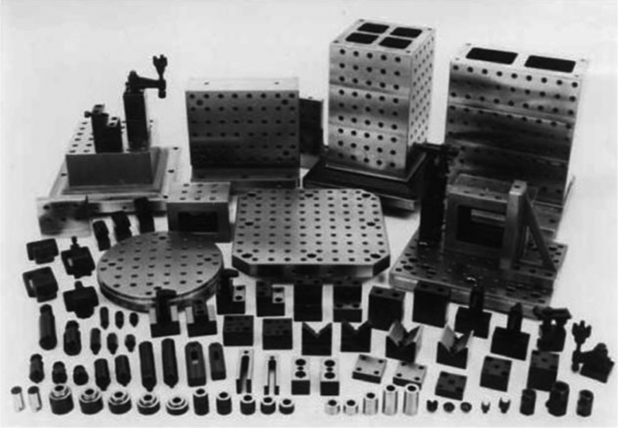
Standard modular fixture components (Courtesy: Carr Lane Manufacturing Company).
Description of fixture entities.
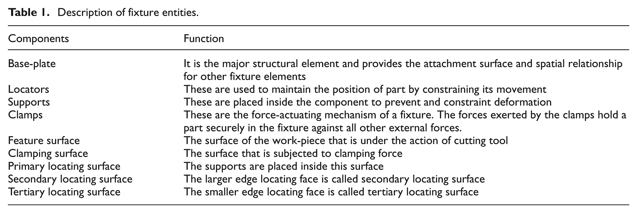
The fixture element’s database consists of components used for design of modular fixtures. Fixture components are grouped into four categories based on their functional abilities and specifications. These are base-plates, locators, supports, and clamps.
Search strategy for fixture layout
The search strategy for fixture layout is designed on the basis of geometric, dimensional, and functional constraints, modular fixture database, and specific setup and fixture plan.
Selection and assembly of part–plate
The selection of the base-plate mainly depends on the overall size, shape of the work-piece, and the type of machining center. In this article, the results for prismatic parts and vertical milling machine are provided. Therefore, the horizontal-shaped base-plates are used. The part dimensions are used for selecting the best base-plate.
The position of part on the base-plate should be selected in order to provide enough area from all sides of part for the assembly of modular fixture components. The origin (0,0,0) of the base-plate is set at the center of plate. For part origin, two possible scenarios are available:
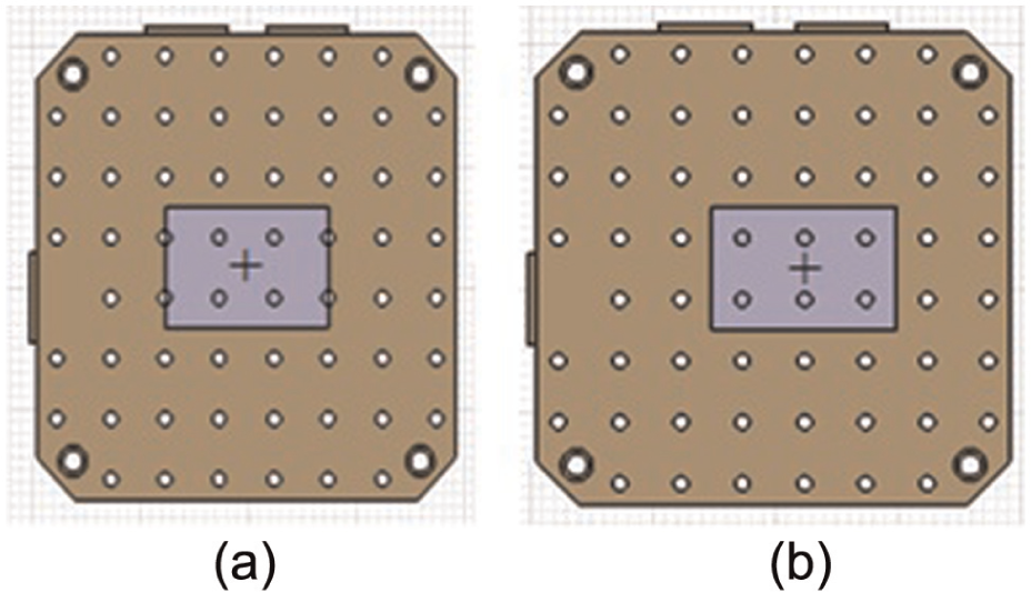
Case 1: If the origin (0,0,0) of part is at the center. In this situation, the part will be secured at the center of base-plate as represented in Figure 4(a). The only condition that must be satisfied is, if the boundary lines of the part are on the base-plate holes’ surface. The check will be made from base-plate holes with reference to the center of the plate. If the holes’ coordinate (x, y, or z value) contains 0 to ±Diameter/2 of base-plate hole’s value, the part boundary would be on base-plate holes as illustrated in Figure 4(a). In this case, the base-plate will be adjusted at a distance equal to center-to-center distance between base-plate holes in the direction of that coordinate. Now the part is in a required feasible location on the base-plate as represented in Figure 4(b).
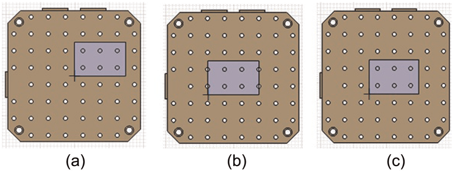
Case 2: If the origin (0,0,0) of part is at the corner. In this situation, the part will be assembled at one of the corners of the base-plate as shown in Figure 5(a). In this case, the plate is moved equal to L/2 and W/2 of part in order to position the part at the same position as presented in Figure 5(b).
Part-Plate Feasible Position (Case 1).
Part-Plate Feasible Position (Case 2).
In the next step, we have to make sure if the boundary line of the part is on the base-plate holes’ surface. The check will be made using the base-plate database. If the holes’ coordinate (x, y, or z value) contains 0 to ±Diameter/2 of base-plate hole value, the part boundary is on base-plate holes as shown in Figure 5(b). In this case, the base-plate is adjusted to a distance equal to center-to-center distance between base-plate holes in the direction of that coordinate. Now the part is in the desired position on the base-plate as represented in Figure 5(c).
Supports’ selection and assembly
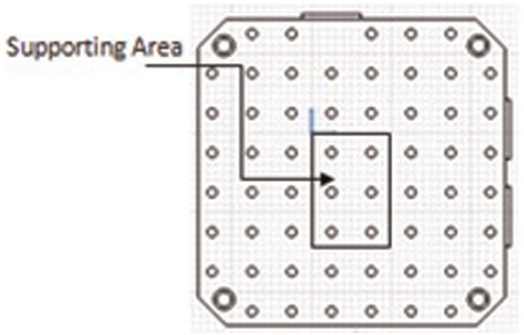
The selection procedure of supports is based on the selected base-plate during the design of the part–base-plate assembly. The selection procedure depends on the selected base-plate holes’ diameter value. The supports are required to be inserted on the base-plate holes within the boundary of the primary locating face of the part. The primary locating face ID is extracted from the fixture planning file. The candidate supporting points should be within the boundary of the primary locating face. This is illustrated in Figure 6.
Supporting area.
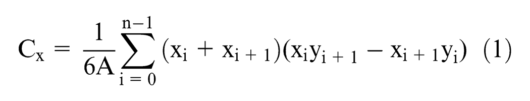
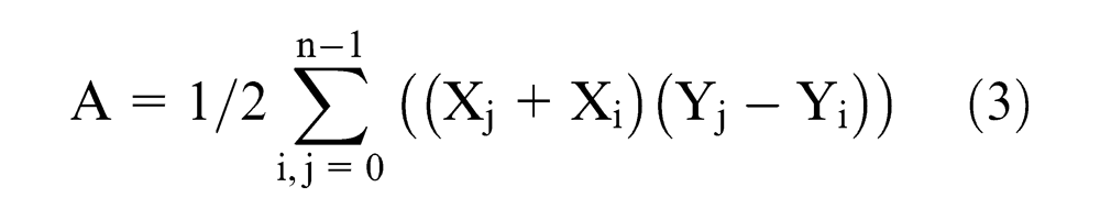
Work-piece stability and supporting accuracy. To ensure work-piece stability and adequate resistance to the cutting force, the supports should be placed at the maximum distant holes. The centroid of the part must be located within the projected bounding region formed by the supporting components. The centroid of a non-self-intersecting closed polygon defined by n vertices (x0,y0), (x1,y1), …, (xn−1,yn−1) is the point (Cx, Cy), where
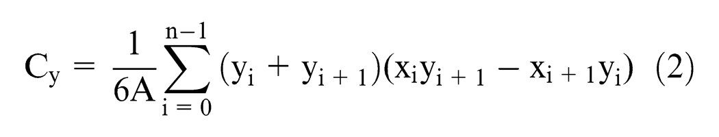
and where A is the polygon’s area which is determined by
According to the “3-2-1 locating principle,” at least three supporting points are required to maintain the stability of the work-piece. These supports must be placed as far apart as possible such that the center of mass of the work-piece is contained within the triangle formed by the three supports. To check that the center of mass is contained within the supporting triangles, the “ray crossing method” is applied. The method calculates the number of times a ray starting from a point P (say) crosses a polygon boundary edge separating its inside and outside. If the number count is even, then the point is outside, and if it is odd, the point is inside as shown in Figure 7. The triangles that did not contain the center of mass of the work-piece should then be eliminated. Among the remaining triangles, the largest one should be picked as the feasible supporting triangle.
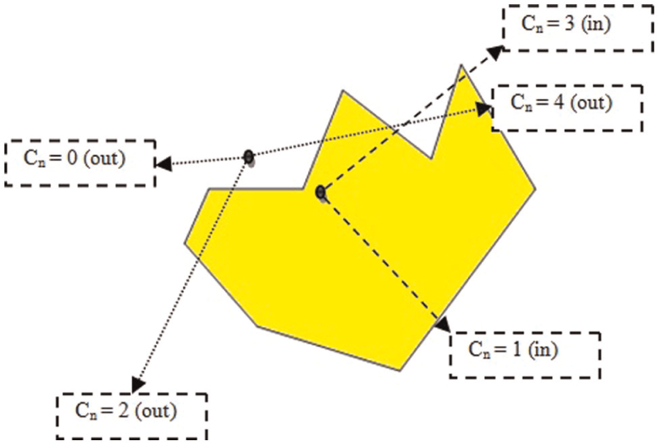
Ray crossing method.
To provide an accurate support, the base-plate movement should be exactly equal to the height of support cylinder to confirm the rigid contact of support and primary locating surface of the part. The following conditions should be considered in order to select feasible hole combinations for the assembly of the supports (Figure 8):
Generate all combinations of supporting triangles from candidate supporting points.
Determine the center of mass of the component by a calculation program.
Apply ray crossing algorithm to check the center of mass inside the triangle(s).
The triangle(s) not within the center of mass will be removed from the list.
Calculate the area of selected triangles.
The triangle(s) with the largest area are selected.
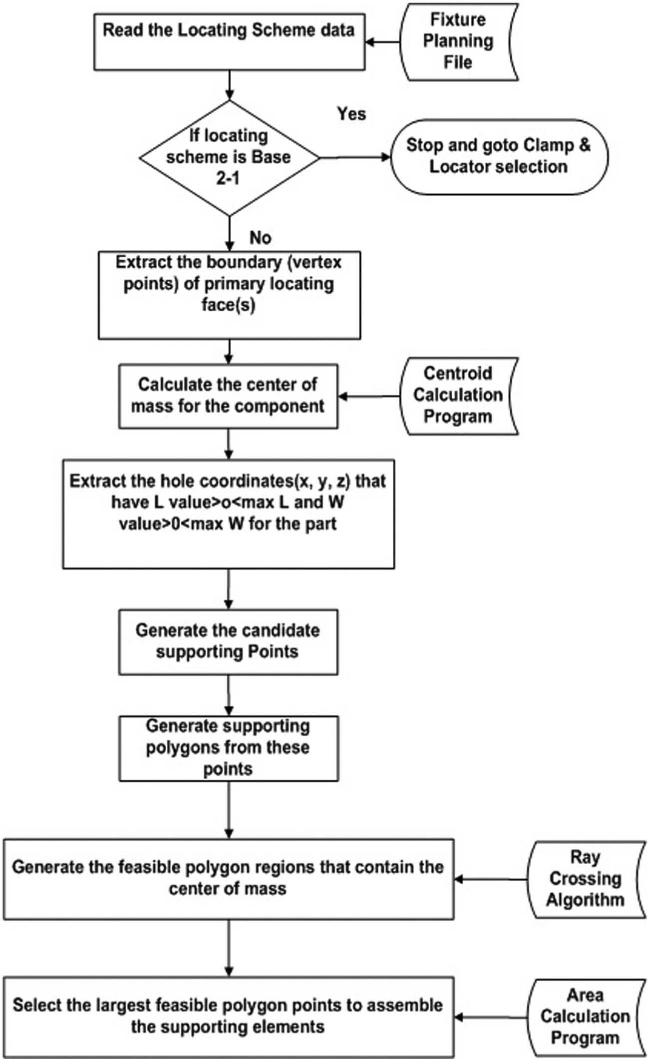
Search strategy for supporting points.
Clamp selection and assembly
The selection procedure for clamps is based on the hole diameter value of the selected base-plate, support height (if present), the projection of clamping arm on the work-piece, the type of clamp, and the clamping arrangement (overhead clamping, side clamping, etc.). The top clamping is preferred since the direction of force exerted by the top clamps is perpendicular to the base-plate, whereas in side clamping, the force direction is parallel to the base-plate.
Clamp accessibility and accuracy. The search for suitable clamping points to avoid machining collision and ensure clamping accuracy (rigidity) is accomplished by checking each clamping hole around the work-piece. The fixturing points that prevent collision and ensure rigid clamping are identified and selected. This strategy is described in the following steps:
Generate candidate clamping points around the work-piece from base-plate database (Figure 9).
Define the first clamping range with respect to the features in the face_outer_bound (edge loop) of clamping face for the selected setup. Then, exclude the holes that are outside this first clamping range to avoid machining collision (Figure 10(a)).
Define the second clamping range with respect to the selected clamping arm width and first clamping range. Then, exclude the holes in order to avoid machining collision due to face_outer_bound features (Figure 10(b)).
Define internal loop filter with respect to the clamping arm length and width and the face_bound (internal features) of clamping face for the selected setup. Then, exclude the holes that are not suitable for the assembly of selected clamp type due to machine tool collision with internal features as presented in Figure 10(a).
To ensure rigid clamping, the clamping arm should be within the bounding region formed by the supporting elements as shown in Figure 11. Therefore, the clamping point must ensure that the selected clamp arm length is inside this bounding region to avoid deflection due to cutting force.
The maximum distant points would be selected after the filtration process so as to determine the desired clamping points.
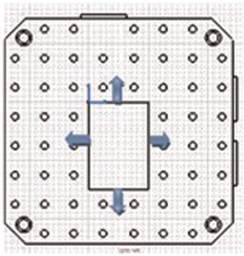
Candidate clamping points.
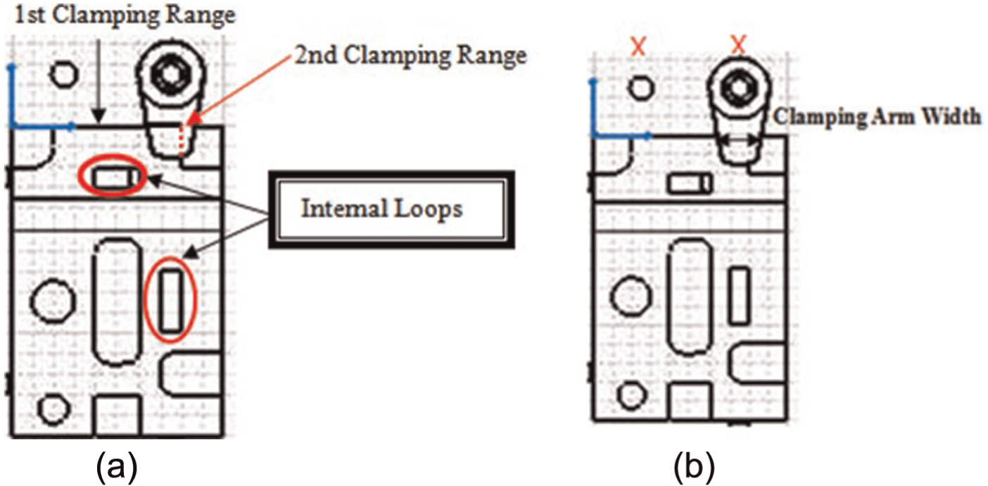
Search strategy for clamping points (First and Second Clamping Ranges).
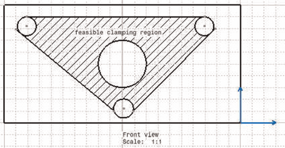
Search strategy for clamping points (Feasible Clamping Region).
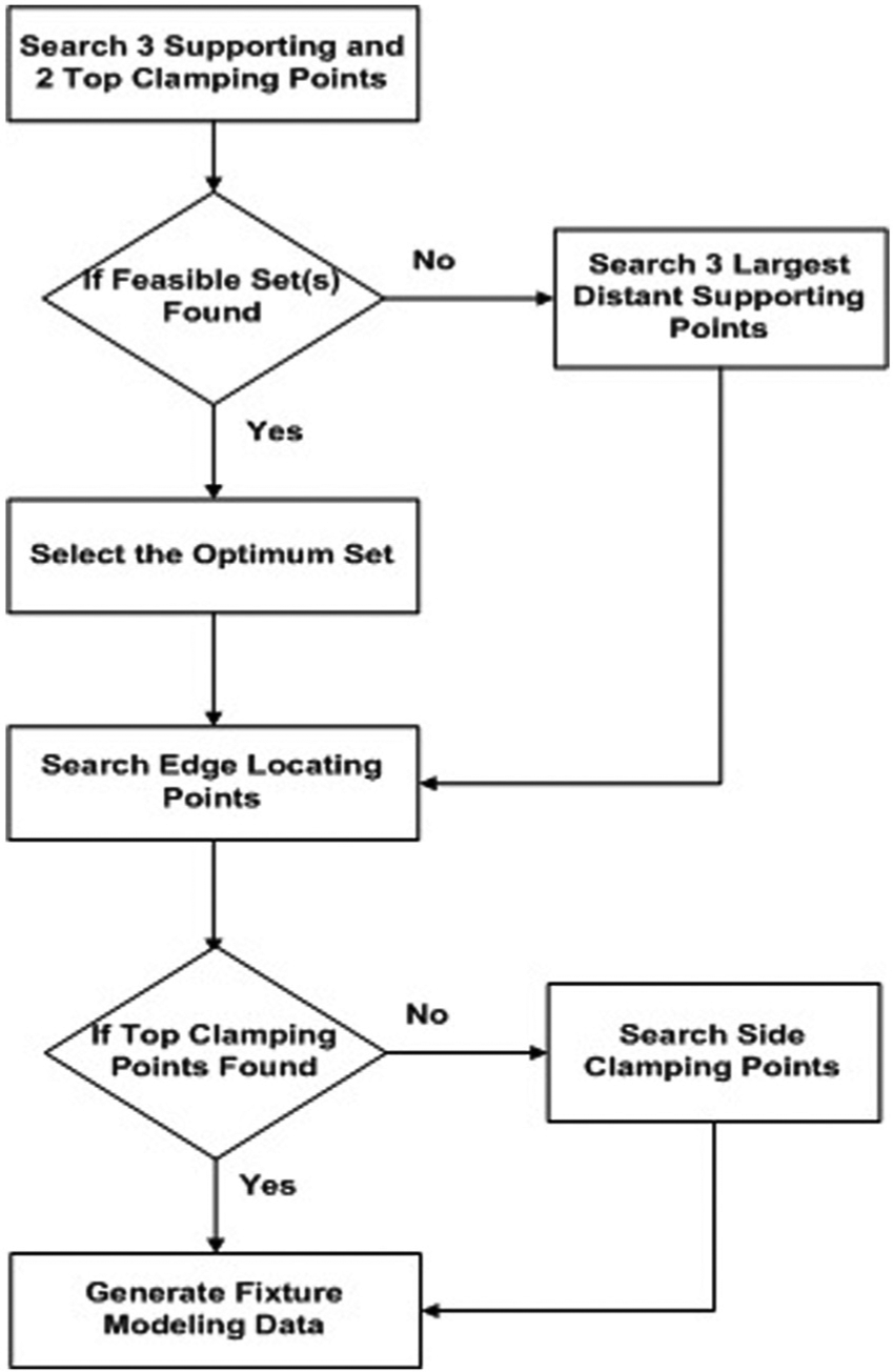
The complete search strategy for the clamp assembly is outlined in Figure 12. This flowchart is for the XY setup location of part only.
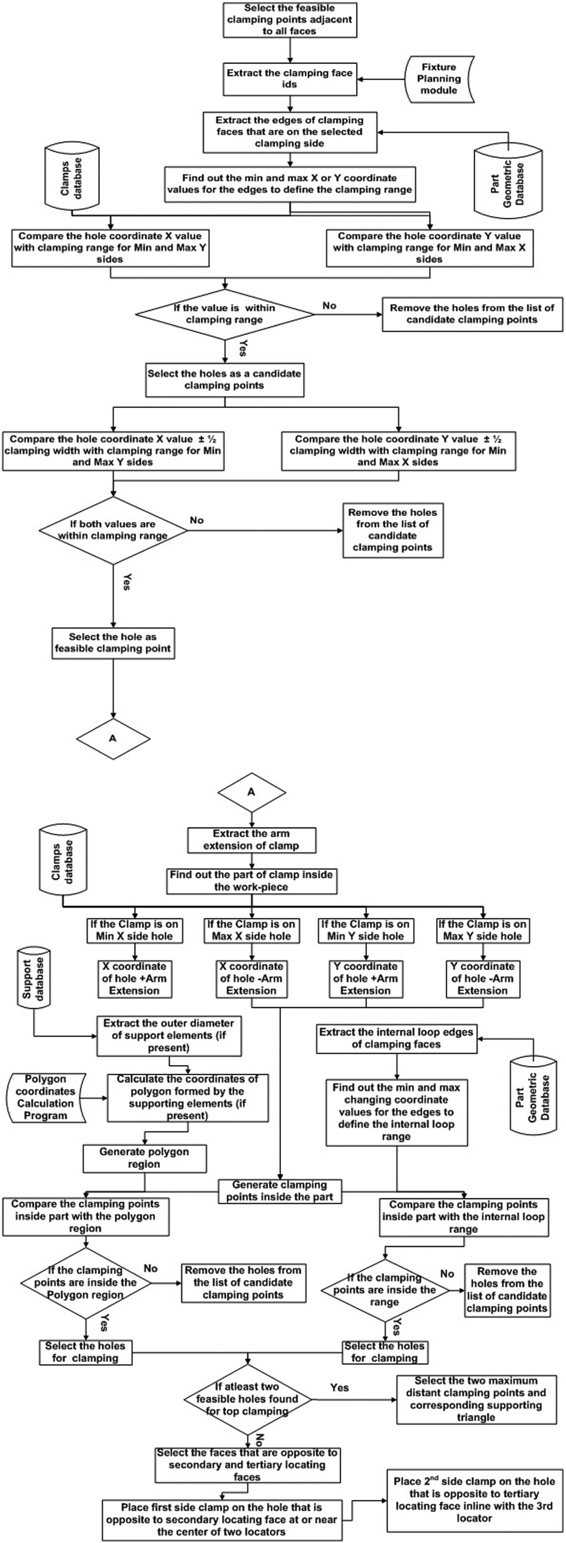
Search strategy for clamp assembly (XY setup).
Selection and assembly of edge locators
The edge locators are placed on the secondary and tertiary locating faces of the part. The selection of the edge locator is based on the base-plate hole diameter, height of edge locator, and locating range. The locating range determines the clearance between the edge locators and the part face, and hence ensures the correct assembly of these locators with respect to the part. The ideal height for edge locator assembly is 1/2 (height of component) + height of support (if present). If no edge locator is found, the edge locator is selected from a list of feasible height values that is closest to the ideal height. The feasible height range is between 1/3 and 2/3 (height of component) + height of support (if present).
Edge locating accuracy and stability. The two edge locators should be placed on the secondary side of the two maximum distant holes and one edge locator at or near the hole adjacent to the tertiary locating face for better accuracy. The locator assembly should contact the secondary and tertiary locating faces of the work-piece within the feasible locating region and to ensure work-piece stability. The search for suitable edge locator points is done by checking each candidate edge locating hole adjacent to the secondary and tertiary locating faces as described in the fixture planning phase (Figure 13). The strategy is further demonstrated in the following steps:
Generate edge locating points from the base-plate database adjacent to the secondary and tertiary sides of the part.
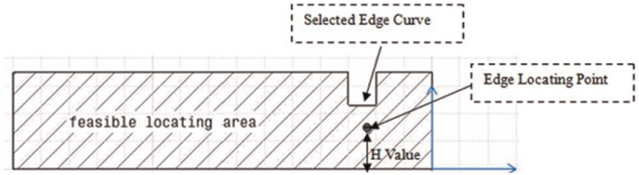
Define the feasible edge locating region through the edge loops of the selected edge locating face(s) (Figure 14).
Compare each locating point height (H) value with feasible locating area.
If the H value of the locating point is inside the feasible locating region, the point will be selected as the candidate edge locating point; otherwise, it is removed from the list of candidate points as shown in Figure 14.
Select two maximum distant points on the secondary locating side and one point at or near the center of the tertiary locating face from the remaining points after filtration.
Candidate edge locating points.
Feasible edge locating points.
The detailed search strategy for the edge locator assembly is shown in Figure 15. This is for the XY setup location of part only.

Search strategy for the edge locator assembly (XY setup).
Fixture assembly
The CATIA VBA editor is used to develop the CATVBA file for final fixture assembly. The file reads in the fixture modeling data and generates the final fixture assembly. The modular fixture database is created using the standard fixture components from “Fixture Works.” The fixture database contains base-plates, supports, edge locators, and clamps. The description of base-plate database is listed here for further illustration.
Base-plate
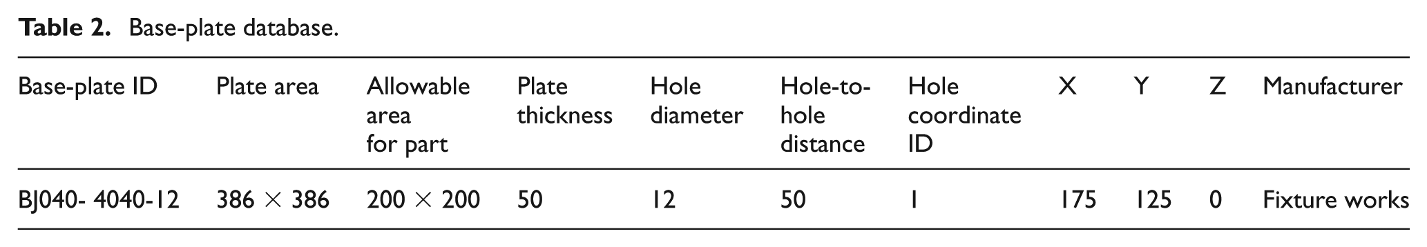
The base-plate element provides attachment surfaces for fixturing elements. For most applications, the base-plate has numerous grid holes which accommodate the locators, supports, and the clamping devices. Horizontal and angle base-plates are the two most frequently used in industry. The base-plate database contains the unique base-plate ID, the maximum area, allowable region for part (safe area) shown as dotted line, height, hole-to-hole distance, hole diameter, and hole coordinate values. These are listed in Table 2 for a sample horizontal (square) base-plate as shown in Figure 16.
Base-plate database.
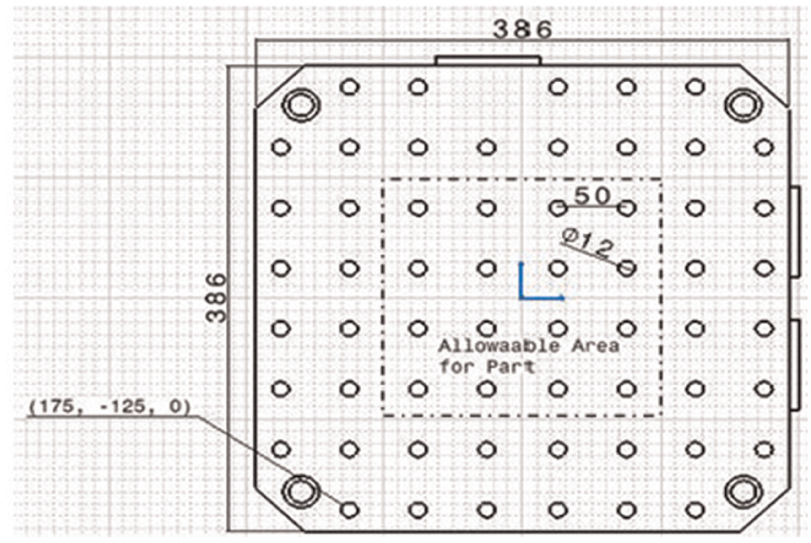
Base-plate.
Implementation and results
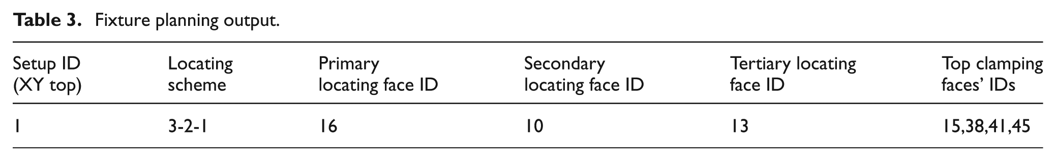
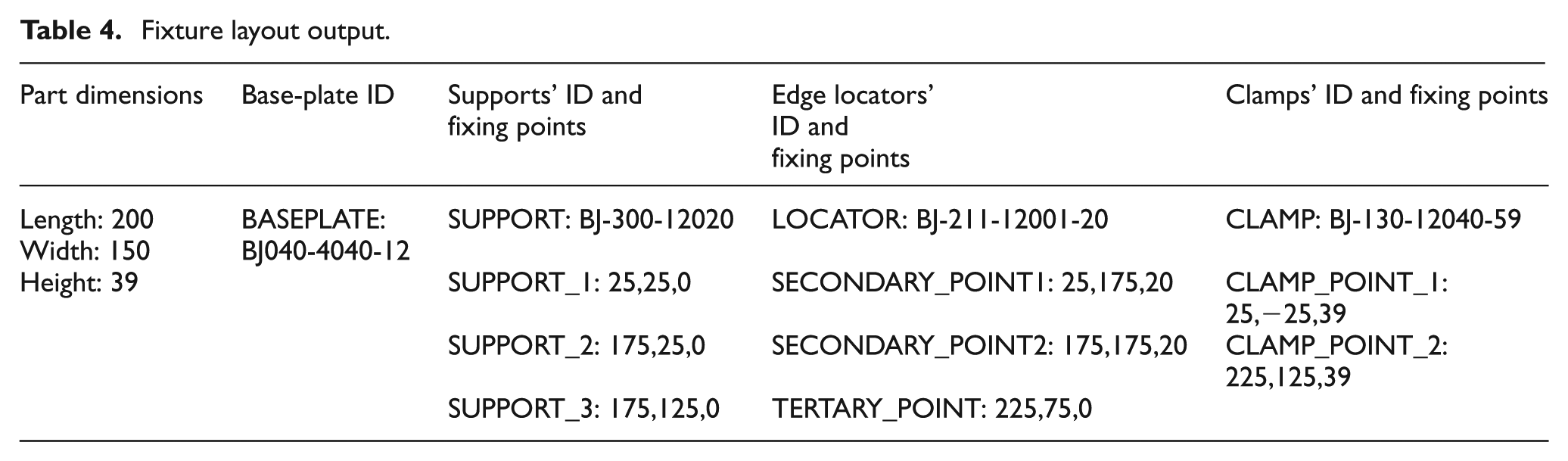
To demonstrate the application of the developed system, a case study is presented to further illustrate the application of the proposed methodology. A sample 3D solid model is designed using CATIA V5 (Figure 17). In this design, there are 63 faces that are extracted from part geometrical database. The process plan file indicated 11 milling features with 1 setup. The fixture planning output is established using the rules developed in the rule-based system. The system will determine the feasible locating scheme, and the locating and clamping faces as listed in Table 3. The fixture layout module was used to determine the suitable fixture components from database and feasible locating and clamping points using the proposed search strategy as described in previous sections (Table 4). The final fixture assembly is done through extracting the fixture layout output using the CATVBA file as shown in Figures 18 and 19.
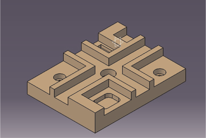
Case study.
Fixture planning output.
Fixture layout output.
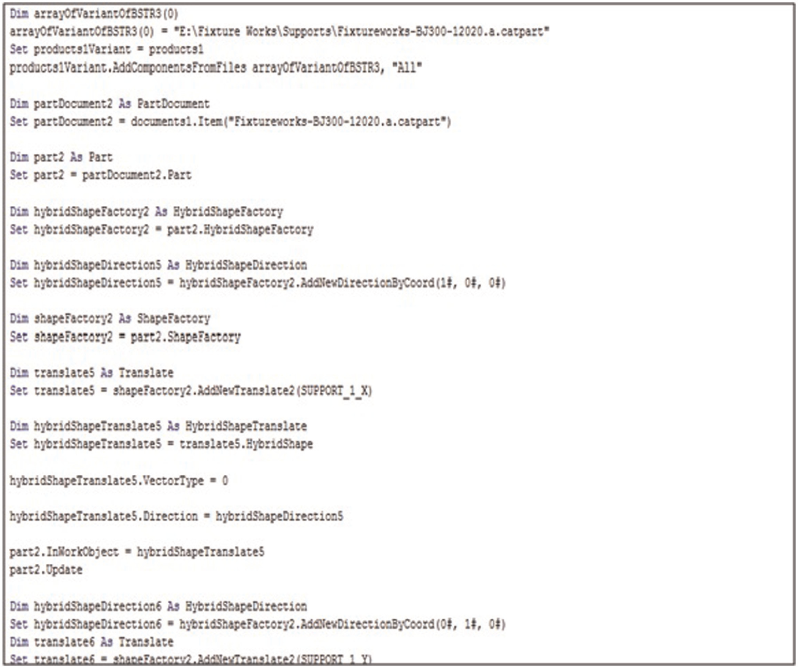
CATVBA file.
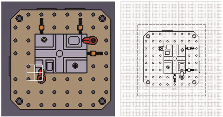
Fixture assembly.
Conclusion
The case study successfully validates the proposed methodology. Logical rules are formulated to determine the locating scheme and the feasible locating and clamping datum for fixture planning module based on part database and manufacturing setup plan. The significance of generating the locating and clamping surfaces restricts the selection and insertion of modular fixture components. Fixture layout is accomplished by developing a commercial database for modular fixture components and the search strategy in order to find the best locating and clamping positions in all different orientations. The final fixture assembly is accomplished using CATIA and CATVBA editor. The CATVBA file automatically extracts the fixture layout data and generates the final fixture assembly using graphical database. The proposed system has the ability to integrate and automate the fixture modeling process.
Footnotes
Acknowledgements
The authors would like to thank the Advance Manufacturing Institute (AMI) at King Saud University and two anonymous referees from the journal (IMech-PartB) for their valuable comments.
Declaration of conflicting interests
The authors declare that there is no conflict of interest.
Funding
This works is funded by National Plan for Science & Technology (NPST), Grant No. 10-INF1280-02, Saudi Arabia.