
Abstract
In this paper, a quadrotor test bed is developed. The technical approach for this test bed is firstly proposed by utilizing a commercial quadrotor, a Vicon motion capture system and a ground station. Then, the mathematical model of the quadrotor is formulated considering aerodynamic effects, and the parameter identification approaches for this model are provided accordingly. Based on the developed model and identified parameters, a simulation environment that is consistent with the real system is developed. Subsequently, a flight control strategy and a trajectory generation method, both of which are conceptually and computationally lightweight, are developed and tested in the simulation environment. The developed algorithms are then directly transplanted to the real system, and the experimental results show that their responses in the real-time flights match well with those from the simulations. This indicates that the control algorithms developed for the quadrotor can be preliminarily verified and refined though simulations, and then directly implemented to the real system, which could significantly reduce the experimental risks and costs. Meanwhile, real-time experiments show that the developed flight controller can efficiently stabilize the quadrotor when external disturbances exist, and the trajectory generation approach can provide safe guidance for the quadrotor to fly smoothly through cluttered environments with obstacle rings. All of these features are valuable for real applications, thus demonstrating the feasibility of further development.
1. Introduction
The development of small and low-cost quadrotors has become popular in recent years owing to the progress of sensors, embedded controllers and communication technologies [1]. The quadrotors can work without skilled pilots in both military and civilian environments that are dangerous or where space is limited for human beings, such as traffic monitoring, reconnaissance, search and rescue, photography, etc. [2].
Several works have demonstrated the capabilities of the quadrotors for those missions, thus illustrating the significant opportunities and challenges that exist in this field. For example, in [1, 3–5], the quadrotors were adopted to transport, construct cubic structures and fly across obstacles. With cameras, the quadrotors could also do the jobs of simultaneous localization and mapping [6]. A quadrotor from the Federal Institute of Technology Zurich was controlled to support an invert pendulum [7]. In addition, two quadrotors have been designed for ball juggling [8]. A large-scale quadrotor (weighing 4 kg with a 1 kg payload) was proposed in [9], and the quadrotor was reported to be stabilized in [10]. Some other examples are aerobatics [11], cooperative manipulation [12], avian-spired grasping [13], etc. As successful fulfilment of these real-time tasks is closely tied with the flight control of the quadrotors, several different flight controllers have been developed over the last decade. In the early years, the controllers were mainly developed to meet the requirements for high-performance trajectory tracking and way-point navigation. For this purpose, a number of conventional control algorithms, such as proportional-integral-derivative (PID), linear quadratic (LQ) [14], backstepping, sliding-mode [15], H∞ with feedback linearization [16], hierarchy [17], fuzzy PID [18], model-based predictive [19] and the Lyapunov function design method [20], were introduced in the flight control, and they have established a solid foundation for subsequent research. Recently, as the demand for applying the quadrotors to the real world keeps increasing, flight controllers are required to be capable of coping with complex real flight scenarios where external disturbances exist such as wind gusts [2]. Therefore, high-performance disturbance rejection control and fault-tolerant control are attracting more and more attention [21, 22]. With well-constructed flight controllers, properly designed trajectory generation approaches are also essential for the quadrotors to cope with cluttered environments and fulfill specific missions. Some representative works of this field may be referred to [3, 23–26], where the desired trajectories were typically generated based on optimal control theory.
To assist this research and development, quadrotor test beds are undoubtedly important [1, 27]. In constructing such test beds, two approaches are mainly adopted. One approach is to build prototypes of the quadrotors as a ground test bench, such as the OS4 aircraft prototype [14, 15, 28, 29], the STARMAC quadrotor [30] and the 6-DOF test bench [27]. Such quadrotor prototypes are useful for studying the dynamics of the quadrotors at the early stage, and in this way the safety for parameter tuning and experimental tests can aways be guaranteed. The other approach is to purchase commercial quadrotors to build the test beds, such as the GRASP test bed [1], QBall X4 [19] and Flying Machine Arena [31]. In these test beds, as the controllers for the quadrotors are directly implemented to the real systems, the real-time flight experiments can provide a convincing way to verify the effectiveness of the developed controllers. In view of the state-of-the-art, it would be valuable if the test bed could inherent the merits from both of these two approaches, that is, providing real-time experiments and also getting rid of the potential risks at the early stage.
This work is therefore motivated to build a quadrotor test bed that can safely verify the developed algorithms in a ground station prior to real-time flights. This is achieved by simultaneously developing a real-time experimental environment and constructing a simulation environment that is consistent with the real system. For this purpose, a commercial quadrotor, a Vicon motion capture system and a control station are firstly integrated within an experimental field. Then the mathematical model of this quadrotor is derived, and the approaches for parameter identification are proposed. Utilizing this model, a simulation environment that is consistent with the real system is developed. In this way, the control algorithms can be developed, tested and refined in this simulation environment, and then directly converted into C-codes and implemented to the real system. As the control algorithms have been preliminarily verified by the simulations, in the development cycle one can significantly reduce and/or remove most of the experimental risks. Comparing the results of simulations and experiments, one can estimate the differences and further improve the parameters of the mathematical model.
To verify the effectiveness of the developed test bed, a conventional proportional-integral-derivative (PID) controller is firstly developed for the quadrotor. The performances of this controller in simulations and experiments are compared, and the feasibilities of the simulations can be thereby verified. Considering external disturbances always exist in real-world environments, a disturbance observer (DOB) is then implemented to enhance the performance of the flight control. The capabilities of this DOB-based controller are verified with a quadrotor suffering from the measurement zero-drift. To further verify the performance of the flight control under complex real-time flight scenarios, three rings are set up in this test bed to demonstrate a cluttered environment. In view of these obstacle rings, a trajectory generation method that is conceptually and computationally lightweight is proposed. The generated trajectory is sent as a reference to the position controller of the quadrotor. With such an implementation, the quadrotor can smoothly pass through the obstacle rings with only small deviations from its desired trajectory.
The contributions of this work are as follows. Firstly, the dynamic model of the quadrotor considering aerodynamic effects is developed, and the parameter identification approaches for the developed model are presented. Secondly, a quadrotor test bed that can effectively fill the gaps between simulations and experiments is developed. Within this test bed, control algorithms can be preliminarily developed and verified through simulations, and then directly implemented to the real system.
In this way, experimental risks and experimental costs can be significantly reduced. Finally, to demonstrate the functionalities of the developed test bed, a DOB-based PID controller and a novel trajectory generation approach, both of which are conceptually and computationally lightweight, are implemented in real-time applications for verification. It is observed that the real-time experimental results match well with the simulation results and the implemented control algorithms can cope well with the cluttered environment, all of which demonstrate the effectiveness of this development.
The remainder of this paper is organized as follows. Section 2 describes the technical approach. The dynamic model is derived in Section 3, and the controller is designed in Section 4. Section 5 presents the trajectory generation approach. Then the results from the simulations and experiments are shown in Section 6, and Section 7 concludes this work.

A Hummingbird quadrotor works with a Vicon motion capture system in the quadrotor test bed
2. Technical approach
Fig. 1 illustrates the structure of the quadrotor test bed developed in this work. This test bed comprises a quadrotor, a pair of wireless routers, a control station, a Vicon motion capture system and a simulation environment. The simulation environment is developed according to the dynamics of the quadrotor. In such an environment, control algorithms for the quadrotor can be developed, tested and optimized, and then directly implemented to the quadrotor. The quadrotor communicates with a ground control station via a couple of wireless routers at a frequency of 50 Hz. To guarantee the real-time performances, the control station is constructed in the Ubuntu operating system. The control station fetches the status data of the quadrotor from the data server of the Vicon motion capture system and sends them to the embedded controller of the quadrotor. The motion capture system runs at 200 Hz and estimates the position of the quadrotor by kinematic fitting the attached markers to it. The block diagram of this test bed is shown in Fig. 2.
All of those components are integrated in an experimental field which is an indoor space with a volume of approximately 5×5×3.5 m3. This field is protected by a nylon net with holes of size 12×12 cm2. A ground mat with thickness 2.5 cm protects the quadrotor from damage during crashes.
2.1 Quadrotor platform
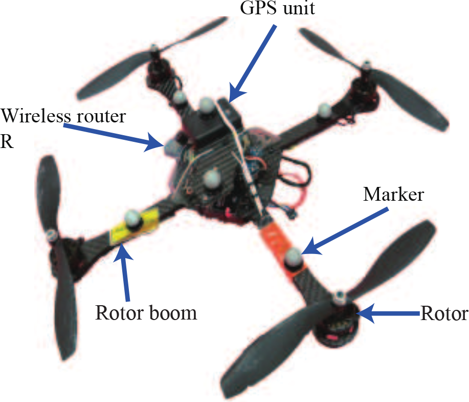
The Hummingbird quadrotor from Ascending technologies is chosen as our quadrotor platform. Its two level processor structure and safety landing mode can help the researchers to pull back the quadrotor when it is out of control. One can develop control algorithms via a Matlab Simulink model, then translate them into C-codes, which can be compiled and directly flashed to the quadrotor's high-level processor. Another Simulink model is provided to send real-time commands to the quadrotor and collect debugging data. All of these features can significantly reduce the development time of the test bed.
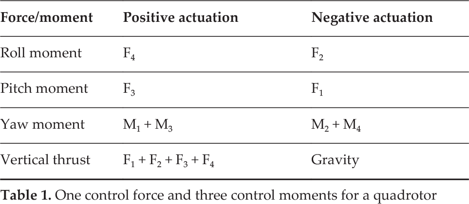
One control force and three control moments for a quadrotor
The Hummingbird quadrotor used in this work is shown in Fig. 3. With approximately 50 cm of tip-to-tip wingspan and 8 cm of height, it weighs 547 g with an additional 200 g payload capacity. When equipped with a 12 V/2100 mAh battery, it can undertake a continuous flight for approximate 20.
2.2 Vicon motion capture system
A Vicon motion capture system with eight cameras (two mega-pixels) is built to estimate the states of the quadrotor [32]. This system provides three benefits. Firstly, it is fast and accurate: running at 200 Hz, the system can measure the position of the quadrotor with a deviation of less than 0.5 mm, which is well beyond the requirements of the experiments. Secondly, it provides a convenient software interface: it works as a server and one can fetch the real-time data from it in a Matlab/Simulink model. Lastly, the system is robust: theoretically, the states of the quadrotor can be estimated when the attached markers are captured by at least three cameras.
3. Modelling and parameter identification
In this section, the dynamic model for the quadrotor is developed.
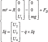
As shown in Fig. 4, there are mainly three kinds of force/moment acting on the quadrotor: gravity (mg), aerodynamic drag force (

The block diagram of the quadrotor test bed
Hummingbird quadrotor
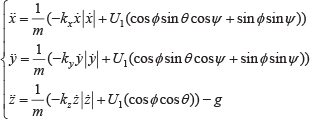
As shown in Fig. 4, these four control inputs are defined in a body fixed frame (XB/YB and ZB), whereas the position (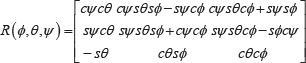
According to the Newton-Euler formalism, the rigid body dynamics are governed by
The measured mass and inertia

The mass m is measured by a digital scale. To measure the inertia of the quadrotor, experiments using a three-wire pendulum [33, 34] are conducted. For each axis, five tests are carried out, and the average value is taken as the final result. The measured mass and inertia are shown in Table 2.
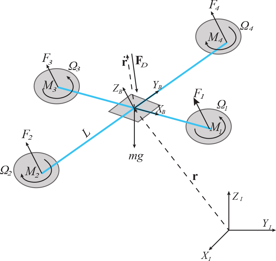
Force diagram of the quadrotor
3.1 Rotor model
The thrust Fi produced by each rotor is commonly calculated as [1, 35]

The moment Mi produced by each rotor is commonly calculated as [1, 35]

The rotor itself is generally described by a first order system [1, 29]


The orthogonal prospective areas of the quadrotor is estimated using the imaging processing technique
3.2 Aerodynamic drag force
In general, the drag force is expressed as [35, 36]

The area 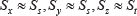
A cascade structure for control system
4. Controller design
The controller is constructed with a cascaded structure as shown in Fig. 6, where the attitude θ and φ are taken as the pseudo control inputs for the translational motion x and y. Based on this structure, one can develop algorithms to fully control a set of four states of the quadrotor. That is, either x, y, z, ψ or θ, φ, z, ψ can be fully controlled simultaneously.
4.1 Attitude controller
According to Eq. (3), as Ixx = Iyy and ψ equals to zero in most cases, the angular acceleration can be expressed as [1, 19, 28, 38]

Firstly, substituting Eq. (4) into Eq. (1) and taking the linearization of it via a Taylor series expansion in the near hovering state, one can obtain

Then, rewriting Eq. (6) as 


The parameters ka can be estimated according to Eqs. (4) and (9), and τ m is identified by an experiment as follows. With a preliminary designed controller in which the RPM input is scaled to 0–2, the quadrotor is conducted to fly with a random trajectory, and the data of this flight are recorded and analysed by the System Identification Toolbox in Matlab. With this procedure, the parameters are identified as ka = 32.2 and τ m = 32.2.
With the identified result of Eq. (13), a PD controller is firstly chosen to stabilize the attitude [1,40]. The closed loop transfer function of attitude with PD control is thereby obtain as

In Eq. (14), there is a closed loop zero at 
According to the Routh's stability criterion, the stability of Eq. (15) can be guaranteed if both kap and kad are positive and kap, < 1000 [41].
4.2 Position controller
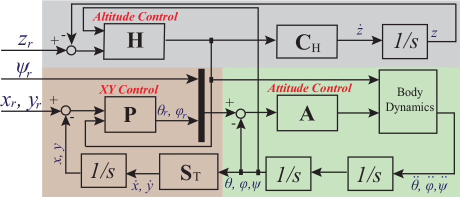
Considering Equations (3) and (7), the dynamics of the position of the quadrotor is expressed as
When the quadrotor flies with a steady speed, the second and higher order derivatives of position are zero. Taking the linearization of Eq. (16) at the steady state,

Attitude control configuration with inner loop

Eq. (17) can be rewritten in a state space form as

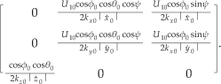
As the matrix 
Since external disturbances always exist in real applications, to eliminate these effects, a disturbance observer is developed as


Trajectory generation of the quadrotor with key points and control points
With the observed disturbance ŵ in Eq. (20), the control input δ
In this way, the effects of the external disturbances are compensated by ŵ, and the control input δu– can simply treat the system as its nominal model Eq. (17).
With the stabilized speed, a proportional controller is developed to stabilize the position of the quadrotor as

In the following discussions, Eqs.(19) and (22) are referred to as the PID controller, and Eqs. (21) and Eqs.(22) are referred to as the DOB-based PID controller.
5. Trajectory generation
In order to generate reference trajectories for the developed position controller to cope with cluttered environments, a trajectory generation approach is developed in this section.
To facilitate the development, the concepts of key point, control point and trajectory segment are firstly introduced as follows. The key point is a way point which the quadrotor must pass through in its specific missions. The control point is the intermediate point introduced to adjust the profile of the trajectory, and the quadrotor will choose whether to pass it or not according to the trajectory generation approach. The trajectory segment is the route between two adjacent control points. In this way, all of the key points can be included in the trajectory segments by a set of properly assigned control points.
As an illustration, a trajectory constructed with three control points (C1 C2, C3) and two key points (K1 K2) is shown in Fig. 8. The dashed line indicates the desired trajectory, and it will be generated as follows.
Firstly, the trajectory segment from C1 to C2 is denoted as
To meet these requirements, a time-dependent function that describes the position of the trajectory along the direction of Key points and control points for the trajectory generation

With Ti (
Apparently, the second order derivative of Γ(t) defined in Eq. (24) is finite, and in this way, the smoothness of the flight can be guaranteed. Therefore, with known key points and control points, a trajectory can be directly generated according to Eqs. (23) and (24).

The step response and error plot for the position controller of the quadrotor
In this work, the quadrotor is designed to fly through the obstacle rings, so the key points are defined at the centre of each ring. To properly include these key points by trajectory segments, the control points are defined as follows. As indicated in Fig. 9, the location for taking off and landing is firstly selected to be a coincident point (C0 and C9). Then five lines are presented: the vertical line for taking off, central lines of three rings and the vertical line for landing. For each two adjacent lines, the perpendicular line between them can be determined, and the corresponding perpendicular feet (C1 ˜ C8) are selected as the intermediate control points. With

The attitude response of the quadrotor
6. Simulations and experiments
In this section, the merits of the development are demonstrated through simulations and experiments.
The structure of the simulation environment is illustrated in the right of Fig. 2. In this environment, the quadrotor model solving the dynamic equations of the quadrotor is firstly developed according to Eqs. (9) and (16). The inputs for this subsystem are RPM commands and the outputs are attitude and position of the quadrotor. The controllers are firstly implemented in the simulation environment for testing and parameter tuning. Then, to experimentally verify their performances, these developed controllers are directly converted into C-codes and flushed to the real system to perform real-time experiments.
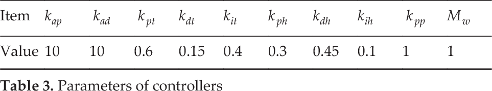
All of the following discussions are based on the experimental results. It should be noted that one of the objectives of this work is to develop a simulation environment that is consistent with the real system. Therefore, to demonstrate the feasibilities of the modelling and simulation environment, the simulation results and the experimental results of the same test are plotted together for comparison. To ensure the controllers are implemented in exactly the same way in both simulations and experiments, the parameters of the controllers in the simulations and experiments are selected with the same values, which are provided in Table 3.
Parameters of controllers
6.1 Step responses of the position controller
The step responses of the position controller are shown in Fig. 10, and the corresponding pseudo control inputs θ and φ are provided in Fig. 11. As the yawing angle is independent from other angles, its step response is also shown in Fig. 11.
The rising time of the translational motion controller is approximately 0.9 seconds. Apart from this, the responses are not exactly the same for the X and Y axes. For the X axis, the settling time with a steady state error of 5% is 2.5 seconds, but is 3.5 seconds for the Y axis. Besides, the position along the X axis can be stabilized with an error of 2.0%, which is less than that of the Y axis. This is caused by mechanic tolerances on the Y axis, since the rotor booms along the Y axis are a bit looser than the other pair. In order to avoid rapid taking off and landing, the gain of altitude controller is smaller. Therefore, its steady state error is larger and the response is also slower. The rising time in the Z direction is 2 seconds, and the settling time with a steady state error of 5% is 8.0 seconds.
The attitude control shows a rapid and smooth response. The maximum value of θ and φ in the whole process is 20 degrees, which satisfies the small angles assumption. The controller closely tracks the reference, with a time delay of less than 0.1 seconds. For the yawing angle, the rising time is less than 0.3 seconds. With an overshoot of 10%, the quadrotor is finally stabilized with a deviation of less than 1% within 1.2 seconds. At the 5th second, when a step input for the X axis is set for the position controller, a perturbation, which might be caused by unmodelled coupling dynamics of the real system and the input saturation of the rotors [8], is found in the yawing angle. In this case, the attitude controller can stabilize the yawing angle within 0.5 seconds.
These results show the quadrotor can be controlled well within the test bed, which verifies the feasibilities of the modelling, parameter identification and controller development. The fact that the results from the experiments match well with those from the simulations implies that the controllers can be firstly verified within the simulation environment, and then directly implemented to the real system.

Comparative experiments between PID controller and DOB-based PID controller

The quadrotor tracks a generated trajectory
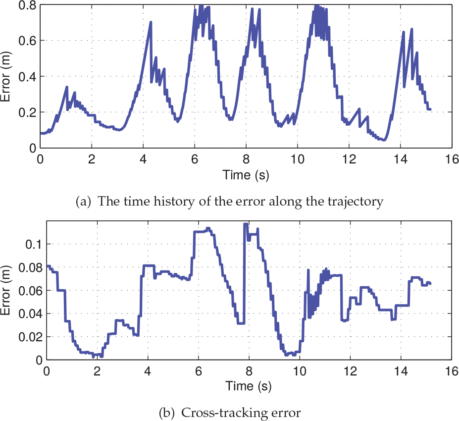
The time history of tracking error along the trajectory and the cross-tracking error
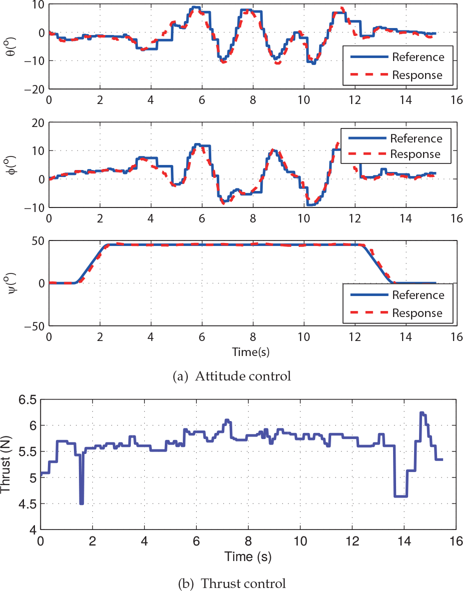
The time histories of the control inputs
6.2 Disturbance rejection
The capabilities of disturbance rejection of the developed DOB-based PID controllers are verified with a quadrotor suffering from measurement zero-drift. After serving over six months in the test bed, structural degradations, e.g., the rigidity of rotor booms decreases, are found in the quadrotor. This causes the gyroscope to stray in the horizontal plane when the quadrotor is in the hovering state. As a result, extra deviations are introduced into the feedback system, or equivalently, nonzero inputs are required to maintain the quadrotor in the hovering state. This will negatively affect the performance of the conventional PID controller. As shown in Fig. 12, the steady state error of the PID controller is as high as 8%. By contrast, as the DOB can estimate these disturbances and thereby effectively eliminate them in the control strategy, the steady state error of the DOB-based PID controller is less than 2.5%. This indicates that the developed DOB-based PID controller can still guarantee the performance of the quadrotor even if external disturbances arise.

The speed and acceleration plot when the quadrotor tracks a generated trajectory
6.3 Trajectory generation
To verify the effectiveness of the trajectory generation approach and the consistency between simulations and experiments, the quadrotor is conducted to track the generated trajectory to fly across three obstacle rings. Each ring's inner diameter is 0.80 m, and their coordinates are estimated by the Vicon motion capture system with K1 =(−0.81, −0.36, 0.75), K2 =(0.20, −1.14, 0.89) and K3 = (0.83, −0.12, 1.34), measured in metres. The two control points selected as the taking off and landing locations are C0 = (0.8, 0.8, 0) and C9 = (0.8, 0.8, 0), which can be modified for each experiment. According to the approach proposed in Section 5, all intermediate control points are


The scenario shows the quadrotor flies across three obstacle rings from (a) to (f)
With w i = 0.2, the trajectory is generated according to Equations (23) and (25). With an Intel Core i5-3470 processor, the entire trajectory can be generated in Matlab within 0.05 seconds, which is fast enough for real-time applications. The corresponding curves are shown in Fig. 13(a). It can be seen that smooth transitions are implemented between adjacent trajectory segments, and the reference trajectory offers a safe guidance for the quadrotor to fly through these obstacle rings. The trajectory is sent to the quadrotor according to the time schedule, and Fig. 13(a) shows the quadrotor tracking the desired trajectory very well. The responses of the corresponding position control are also shown in Fig. 13(b), which shows the details of the trajectory tracking process. It can be seen that the position of the quadrotor falls behind the moving reference point. Therefore, the dynamic error in this process is as high as 0.8 m, as shown in Fig. 14(a). However, the feasibility of the development isnot affected by this shortage. As indicated in Fig. 14(b), the cross-track error is less than 0.12 m, which shows that the reference trajectory is closely tracked and therefore enables the quadrotor to safely pass through the settled rings in the test bed.
The corresponding control inputs are shown in Fig. 15. The attitude θ and φ are the pseudo control inputs for the translational movement, and the thrust steers the altitude movement It should be noted that in the trajectory tracking process, the yawing angle is π/4, therefore, θ and φ cooperatively steer the translational motion in the way of Eq. (16).
The time history of the speed and the acceleration of the quadrotor are shown in Fig. 16. The maximum speed during the flight is approximately 1.5 m/s, and the maximum acceleration is 2.5 m/s2 through the entire flight. All of this indicates that the quadrotor can smoothly pass through cluttered environments at moderate speed.
The scenarios of the real-time experiments are shown in Fig. 17.
From all of the plots, it can be seen that the provided trajectory generation approach can provide a feasible guidance for the quadrotor to fly through the cluttered environment, and the developed PID controller can track the generated trajectory well. In addition, the simulations provide good predictions for the controller development. One can therefore verify the performances of the control algorithms through simulations prior to implementing them to the real systems, which would significantly reduce time and cost of development.
7. Conclusion
This work has developed a quadrotor test bed, which consists of a commercial quadrotor platform, a Vicon motion capture system, a control station and a simulation environment. The simulation environment is developed according to the quadrotor's dynamics, thus the behaviours of the quadrotor can be preliminarily verified through this environment. To illustrate such functionality, simulations and experiments are performed comparatively for the flight controllers and trajectory generation. The results show that the results from the experiments match well with those from the simulations, and the quadrotor can be well controlled to smoothly fly through the cluttered environment. This indicates that one can easily develop and refine these control algorithms in the simulation environment, and transplant the developed algorithms to the real system with no gaps in the controller implementation process. Therefore, the risks during experiments are minimized, and the development time can be reduced. All of these facts demonstrate the merits of this development.
In future, more research will be carried out to verify and improve the dynamic model of the quadrotor, and the trajectory generation approach will be improved for high-speed flight and obstacle avoidance.
Footnotes
8. Acknowledgements
This work was funded by the Open Foundation of the State Key Laboratory of Fluid Power Transmission and Control.