
Abstract
The performance of quadrotors can be significantly disturbed in the presence of wind. In this article, a simple-to-implement attitude controller is proposed to render a robust and accurate trajectory tracking in the presence of disturbance and model uncertainties. The attitude controller design is based on quantitative feedback theory. A fuzzy logic controller is further employed to provide a satisfactory position trajectory tracking for the quadrotor. The performances of the controllers, in terms of disturbance rejection and trajectory tracking, are experimentally studied. Finally, a flight scenario is performed that compares the performance of the designed quantitative feedback theory-fuzzy control scheme with the ArduCopter controller.
Keywords
Introduction
Unmanned aerial vehicles (UAVs) have emerged as popular platforms in various applications such as rescue missions, 1 firefighting, 2 and surveillance. 3 These vehicles can be operated in dangerous environments with relatively low cost and without putting human at risk. 4 A specific kind of UAVs, the quadrotors, have attracted a lot of attention in the contemporary robotics because of their two main advantages over other vertical takeoff and landing UAVs, namely their mechanical simplicity and minimum damage in case of collision. 5 As a result of this popularity, a broad range of control techniques have been designed and evaluated to improve the flight performance of quadrotors.
Numerous research studies have investigated the attitude and position controllers’ design and implementation, such as Proportional integral derivative (PID) and Linear quadratic (LQ) techniques, 5 –7 Lyapunov-based control, 8,9 sliding mode control, 10,11 backstepping control, 10 integral backstepping, 12 fuzzy logic control, 13 and visual-based techniques. 14 The importance of considering the model uncertainties and external disturbances at the controller design stage has been noted by many researchers. Several simulation studies have concentrated on the effects of the external disturbances on the flight. 15 –17 More recently, some studies focused on disturbance rejection in the controller design procedures and experiments. Hoffmann et al. 5,18 derived a detailed dynamic model for aerodynamics of quadrotors with non-zero free-stream velocities. A proposed feedforward compensator for aerodynamic effects based on the derived dynamics combined with a simple linear controller was utilized on the STARMAC testbed. Dong et al. 19 designed a disturbance observer (DOB)–based controller with the backstepping technique. The designed DOB serves as a compensator which can effectively attenuate external disturbances. Alexis et al. 4 developed a switching model predictive attitude controller considering the effect of disturbances at the controller design phase.
Most of the experimental works in disturbance rejection area propose complex control algorithms or compensators based on the extended dynamic models. In this article, simple-to-implement attitude and position controllers are designed to render a robust and accurate trajectory tracking in the presence of external disturbance and model uncertainties. The quantitative feedback theory (QFT) method is chosen to design a linear fixed gain attitude controller. QFT was first developed by Horowitz in early 1960. 20 It is a controller design technique in frequency domain using the Nichols chart to develop a desired robust design over a specified region of plant uncertainties. Using the QFT method, it is guaranteed that the desired performance specifications are satisfied in spite of the system uncertainties and disturbances. The transparent design procedure of the QFT method facilitates the designer to reach a trade-off between controller performance and complexity. Using the QFT method, system stability, disturbance rejection, and response tracking criteria for the entire range of plant uncertainties are taken into account at the controller design phase. Considering the fact that fuzzy logic controllers (FLCs) are effective replacements for experienced human operators, 21 the fuzzy logic technique is also used to design a position controller. The combined QFT attitude and fuzzy position controller, which hereafter is referred to as the QFT-fuzzy controller, is shown to outperform the inbuilt ArduCopter, an open-source controller for commercially available multirotors, in terms of trajectory tracking. The article is structured as follows. In the second section, quadrotor dynamics are presented. In the third section, the designed criteria and the development of QFT attitude and fuzzy position controllers are presented. Experimental results which validate the efficacy of proposed controllers are presented in the fourth section. The final section draws the conclusions.
Quadrotor dynamics
Rigid body dynamics
The derivation of the equations of motion for a quadrotor requires two reference frames: the earth-fixed frame and body-fixed frame (see Figure 1). The world-fixed frame consists of axes X, Y, and Z with Z pointing upward. The body-fixed frame is attached to the center of gravity of the quadrotor with x pointing to rotor 1, y pointing to rotor 4, and z perpendicular to the plane of rotors pointing upward in the hover state. Z–X–Y Euler angle sequence (ψ,φ,θ), referred to as yaw, roll, and pitch, respectively, is used to model the orientation of the quadrotor in the earth-fixed frame.
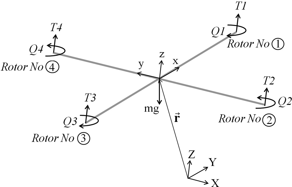
Quadrotor free body diagram: earth-fixed frame {XYZ} and body-fixed frame {xyz}.
The thrust,Ti, and torque, Qi, generated by each rotor act perpendicular to the plane of rotors. Vehicle mass is m, the length between rotors and z-axis is called quadrotor arm and is denoted by l, acceleration due to gravity is g, the position of the quadrotor in the earth-fixed frame is shown by


The applied disturbances to the inner loop and outer loop systems are shown by Di and Do , respectively. R denotes rotation matrix from the body-fixed frame to the earth-fixed frame and is given by

where cθ and sθ represent cos(θ) and sin(θ), respectively, and similarly for φ and ψ. The components of angular body rates are p, q, and r. These rates are the ones measured by gyroscopes and are related to the derivatives of Euler angles according to the following equation

This equation is valid for small changes of Euler angles.
Motor dynamics
Each motor with angular speed, Ω i , produces a thrust, Ti, and a torque, Qi, according to these equations


where kT and kQ are thrust and drag coefficient, respectively. The exact relationship between the actual and desired motor speed is a complex function of motor controller and motor/propeller dynamics. 22 However, in previous studies, the first-order model was successfully used in the controller design phase. 5,12,22 The actual rotor speed is therefore related to the desired rotor speed by the following equation

System parameters
The commercially available quadrotor made by 3D Robotics Company to perform experimental evaluations is shown in Figure 2. 23 The nominal values of the quadrotor parameters were identified experimentally. 23

Quadrotor used for experimental evaluations.
Quadrotor’s inertia matrix, I, was measured using the bifilar pendulum formula around each axis. Two experimental setups were designed to measure the values of thrust and torque coefficients, kT and kQ for the rotor/propeller units of the system under investigation. The value of motor gain, km , for the system used in this study was estimated by the values which have been given in previous studies for similar rotors. In this work, ±25% deviation for quadrotors parameters is considered. The designed controller has to meet the criteria if the plant parameters change within the mentioned ranges. The identified nominal system parameters and their ranges of uncertainties are given in Table 1.
Quadrotor parameters and corresponding ranges of uncertainties.

Control system
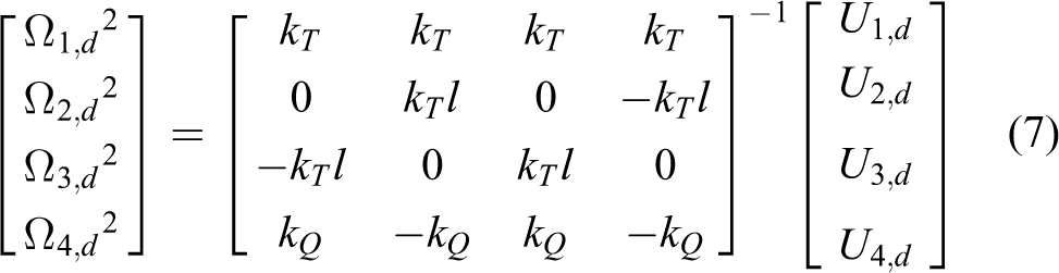
The quadrotor is controlled by nested feedback loops depicted in Figure 3. The inner loop attitude controller uses gyros, accelerometers, and a fusion algorithm to control the orientation of the quadrotor at approximately 400 Hz. Similarly, the outer loop position controller uses GPS, accelerometers, and a fusion algorithm to obtain the position of the quadrotor at approximately 100 Hz. The inner loop controller is designed by the QFT method and is based on the family of linearized angular dynamics of the quadrotor. The QFT controllers are designed for roll and pitch angles. The existing PID rate controller is used for the yaw angle and the desired yaw rate is fixed to zero. The outer loop controller is designed based on the fuzzy logic technique. The vector of desired rotational speeds of rotors can be calculated from the desired control input torques, U2,d, U3,d, and U4,d, and thrust, U1,d, by the following equation

Block diagram showing entire system and controllers.
Di denotes the disturbing torque vector that tends to disturb the quadrotor attitude. Similarly, Do refers to the disturbing force vector that affects the trajectory tracking performance of the vehicle. These torques and forces are caused by various factors, including atmospheric drag, wind gust, payloads, and an uneven and not perfectly symmetric mass distribution of the vehicle.
Attitude control
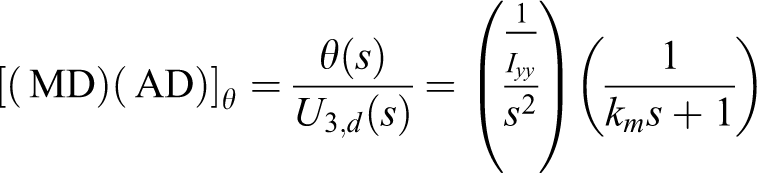
Figure 4 illustrates the two-degree-of-freedom QFT attitude control structure where MD and AD denote motor dynamics and linear attitude dynamics, respectively. Employing the QFT method, a prefilter, IPF, and a controller, IC, are designed such that the considered performance criteria are satisfied (readers are referred to Houpis et al. 20 for a detailed QFT design procedure). For small angles, the angular equations of motion can be linearized around an operating point corresponding to the hover state. The linearized attitude equations of motion are decoupled about each axis, consequently control input torques can be implemented independently.

Two-degree-of-freedom QFT attitude controller structure. QFT: quantitative feedback theory; IPF: inner loop prefilter; IC: inner loop controller.
The linearized transfer function and the values of uncertain plant parameters for pitch angle are as follows


The transfer function for the roll angle is identical due to similar dynamics and parameters.
QFT design involves three basic steps that are discussed in detail as follows:
Generation of QFT plant templates
At each frequency, the plant frequency response set for the whole range of parametric uncertainties is called a template. Plant templates are plotted for a selected range of frequencies on the Nichols chart. The design frequencies are selected as
Computation of QFT bounds based on performance specification
Given the plant templates, QFT converts closed-loop magnitude specifications into magnitude and phase constraints on the Nichols chart. These constraints are called QFT bounds. Three QFT performance specifications are considered in this project, namely, robust stability, disturbance rejection at plant output, and tracking criterion. The tracking criterion is a restriction on the closed-loop reference tracking performance. The tracking criteria bound the closed-loop system responses according to the following inequality

where T L and T U are the lower and upped bounds and are chosen to be following for the system under investigation

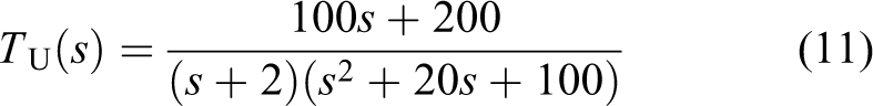
The step responses pertaining transfer functions T L and T U are plotted in Figure 5. The lower and upped bounds are designed to meet specific qualifications in time domain, namely, zero over shoot and maximum settling time of 1 s (readers are referred to Houpis et al. 20 for detailed QFT tracking bounds design procedures).

Time responses of desired tracking bounds; upper bound and lower bound are TU(s) and TL(s) defined by (10) and (11), respectively.
The second design criterion is robust stability. Robust stability criterion constraints the peak magnitude of the closed-loop frequency responses as follows
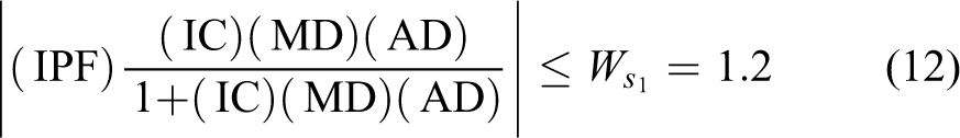
This specification is equivalent to gain and phase margins of 1.83 dB and 54.3°. The third and final design criterion is disturbance rejection in the plant output. This criterion constraints the peak magnitude of the closed-loop frequency responses as follows

Controller and prefilter design
QFT bounds and the nominal loop transfer function,
QFT design bounds and nominal loop transfer function before controller design on the Nichols chart at design frequencies (rad/s). QFT: quantitative feedback theory.
Based on the QFT technique, the nominal loop transfer function has to be shaped such that it lies above the tracking bounds and outside the stability and disturbance rejection bounds. The process of shaping the nominal loop transfer function is done by adding zeros and poles to the control transfer function and is called loop shaping.
The nominal loop transfer function after controller design is illustrated in Figure 7. The designed controller is given below


QFT design bounds and nominal loop transfer function after controller design on the Nichols chart at design frequencies (rad/s). QFT: quantitative feedback theory.
It was observed that the cost of placing an integrator in the controller was an increase in the loop gain. Despite this, an integrator is desirable since it eliminates the steady-state errors. Two zeros were then placed to satisfy the design criteria with a minimum loop gain. The designed inner loop controller, IC, guarantees that the variation of the closed-loop responses is less than or equal to that allowed by the tracking bounds. Therefore, to satisfy the tracking criterion, a prefilter is designed using the Bode plot to put the closed-loop frequency responses in the desired envelop. The designed prefilter is given below

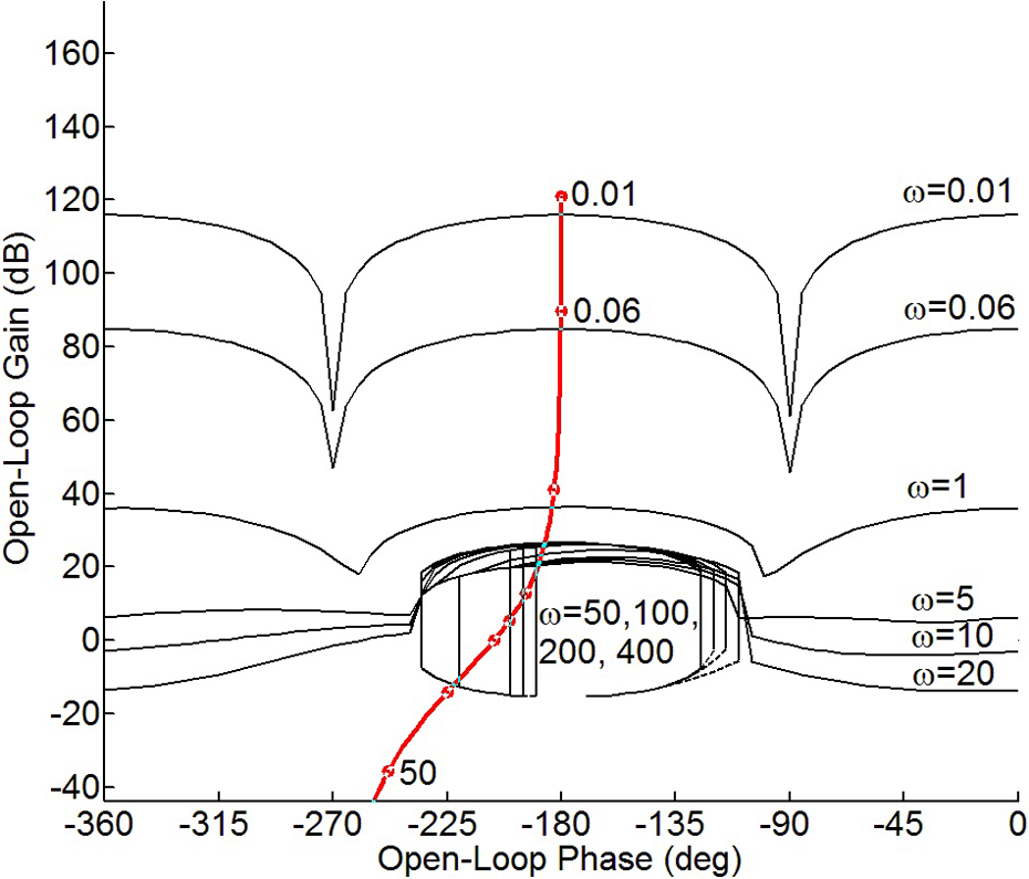
The frequency responses of the system before and after the prefilter design are illustrated in Figure 8 for the whole ranges of uncertainties given in Table 1. The step responses of the linearized system after controller and prefilter design for the whole ranges of uncertainties given in Table 1 are illustrated in Figure 9 (readers are referred to Houpis et al. 20 for detailed loop shaping and prefilter design procedures).

Frequency responses using the QFT controller with and without prefilter for the whole range of parametric uncertainties given in Table 1. QFT: quantitative feedback theory.

Step responses using the QFT controller and prefilter for the whole range of parametric uncertainties given in Table 1; upper bound and lower bound are TU(s) and TL(s) defined by (10) and (11), respectively.
Position control
The position of the quadrotor is usually controlled by human operators using radio remote controls. Considering the fact that rule-based controllers mimic the control behavior of skilled operators using IF–THEN fuzzy rules,
21
fuzzy logic technique is employed here to design a position controller for the quadrotor. The position control structure is shown in Figure 3. It consists of three FLCs to control the position of the quadrotor in X, Y, and Z directions using the errors and corresponding rate of errors. The method used in this work is based on Mamdani’s minimum operation rule and the center of area defuzzification technique.
24
The altitude error is (Z−Zd) and the rate of altitude error is (

Membership functions for input position error in X and Y directions.

Membership function for input position error in the Z direction.
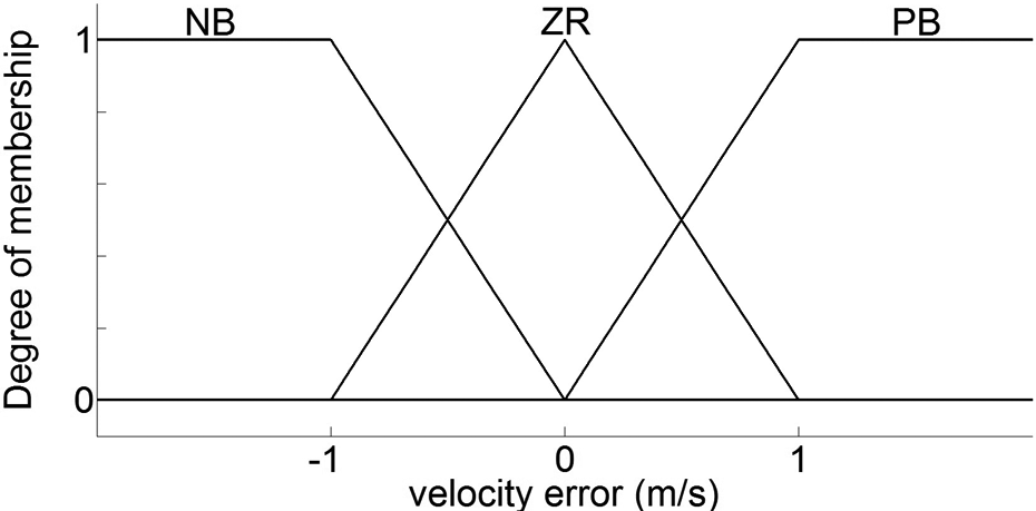
Membership functions for input velocity error in X, Y, and Z directions.

Membership functions for output attitude angles (θd , ϕd ).

Membership function for output thrust, U 1,d .
To generate the output of the controllers, the inputs of errors and the rate of errors are used by the rules given in Table 2 and the output membership functions shown in Figures 13 and 14. The rules in Table 2 should be read as follows. For instance, if the error is ZR and the rate of error is PB, then the output is PS. The resulted output should be defuzzified to be used as system control inputs. The mean-area defuzzification method is employed for this purpose. 13
Table of rules to determine fuzzy controller outputs.

NB: negative big; NS: negative small; ZR: zero; PS: positive small; PB: positive big.
Experimental evaluation
To investigate the performance of the controllers, various experiments were performed. The experimental platform consists of a 2013 3DR Quad D frame and electronics kit, a Pixhawk autopilot system, 3DR UBlox GPS and compass kit, 3DR 915 MHz telemetry radio system, and a Futaba 14SG radio system and receiver. The inner loop attitude and outer loop position controllers were written in C++ and uploaded to the Pixhawk flight controller unit. A low-pass prefilter (with a cut-off frequency of 20 Hz) was implemented to attenuate the generated noise prior to calculating the first and second derivatives of the Euler angle errors. The step response and disturbance rejection performance of the QFT attitude controller were examined first. In these experiments, the quadrotor was attached to a gimbal to constraint its motion in space while allow it to rotate freely around three axes, allowing up to 45° for the roll and pitch (see Figure 15). Note that the friction of the gimbal is considered as an external disturbance applied to the quadrotor. The disturbance rejection performance was then studied in the hover state. Next, the performance of the combined QFT-fuzzy controller was investigated by performing a square-shaped trajectory tracking. Finally, in order to further signify the development presented here, the performance of the designed autopilot is experimentally compared with ArduCopter, an open-source autopilot code available for the Pixhawk flight controller unit. These experiments were conducted in the outdoor environment in one day with an average wind speed of 15 ± 5 km/h. The position of the quadrotor was recorded using GPS.
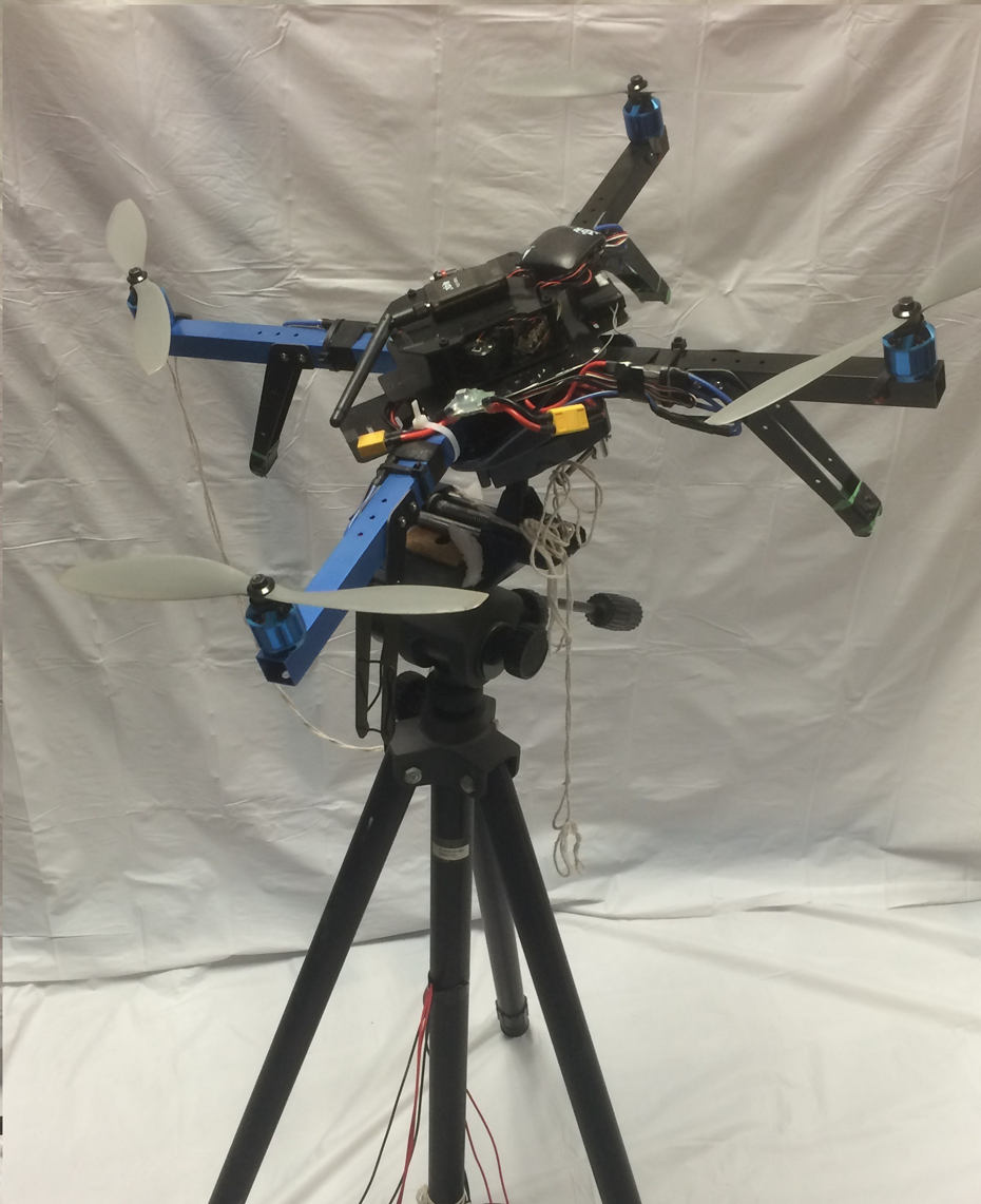
Custom made test stand to evaluate designed attitude controller.
Attitude control experiments
The first set of experiments was performed to validate the tracking performance proposed in the QFT design criteria. The normalized step responses using the QFT controller and prefilter given by equations (14) and (15) are depicted in Figure 16 for 16 experiments in tracking various desired step inputs having magnitudes of 5°, 15°, and 25°. As it is seen in Figure 16, the step responses are within the acceptable envelope of time responses restricted by the upper and lower bounds defined by equations (10) and (11).

Experimental normalized step responses using the attitude QFT controller and prefilter in tracking various desired step inputs having magnitudes of 5°, 15°, and 25°; upper bound and lower bound are TU(s) and TL(s) defined by (10) and (11), respectively. QFT: quantitative feedback theory.
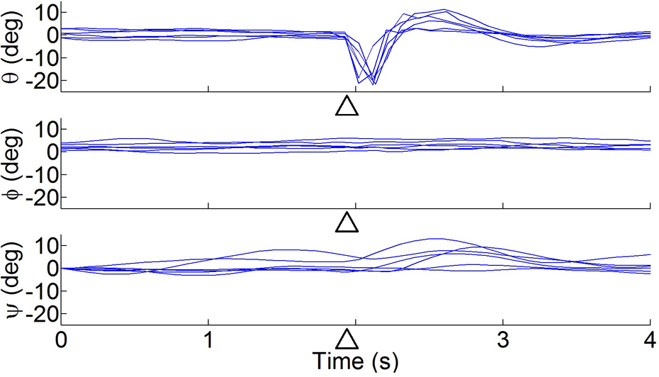
Next, the disturbance rejection performance of the quadrotor while it is attached to the gimbal is investigated. The responses of the quadrotor on the gimbal to 20° additive pitch angle disturbances for six experiments are illustrated in Figure 17. The corresponding control signals are depicted in Figure 18. The disturbances were applied as follows: A 100 g weight was attached to the quadrotor frame below the rotor no. 3 by a string with a length of 0.63 m and was held in the plane of rotors. The weight was then let go freely from the plane of rotors in a certain time illustrated by triangles in Figures 17 and 18. The mass was hung for 1 s and then gradually removed within the next 1 s.

Six experimental responses of quadrotor on a gimbal to pitch angle disturbance using the QFT controller; disturbance was applied around 2 s as indicated by the triangles. QFT: quantitative feedback theory.

Corresponding control signals for the quadrotor on a gimbal under pitch angle disturbance using the QFT controller; triangles show the time when disturbance was applied. QFT: quantitative feedback theory.
As is seen in Figure 17, the QFT controller is able to attenuate the applied disturbances in approximately a second.
A similar set of experiments was done to investigate the disturbance rejection performance, while the quadrotor was freely hovering in space. The same disturbances were applied to the quadrotor in the hover state. As it is seen in Figures 19 and 20, the disturbances were attenuated in approximately a second.
Six experimental responses of the hovering quadrotor to pitch angle disturbance using the QFT controller; disturbance was applied around 2 s as indicated by the triangles. QFT: quantitative feedback theory.

Corresponding control signals of the hovering quadrotor under pitch angle disturbance using the QFT controller; triangles illustrate the time when disturbance was applied. QFT: quantitative feedback theory.
Position control experiments
A square-shaped trajectory depicted in Figure 21 was followed to investigate the performance of the QFT-Fuzzy controller. The trajectory is defined by eight waypoints illustrated by circles in Figure 21. The desired and actual attitude of the quadrotor following the trajectory using the QFT-fuzzy controller is shown in Figure 22 for a typical experiment. The corresponding desired and actual position of the quadrotor following the trajectory using the QFT-Fuzzy controller is illustrated in Figure 23. The same trajectory was followed using the ArduCopter controller and the corresponding results are shown in Figures 24 and 25.

Square-shaped flight scenario in constant 5 m altitude.
Components of desired and actual attitude using the QFT controller for the square-shaped flight scenario. QFT: quantitative feedback theory.

Components of desired and actual position using the QFT-fuzzy controller for the square-shaped flight scenario. QFT: quantitative feedback theory.

Components of desired and actual attitude using the ArduCopter attitude controller for the square-shaped flight scenario.

Components of desired and actual position using the ArduCopter controller for the square-shaped flight scenario.
A comparison of five experiments performed by each controller shows the average absolute deviation of 0.51° and 1.28° for reference tracking error using the QFT and ArduCopter attitude controllers, respectively. The values of average absolute deviation for each experiment in each direction are listed in Table 3.
Comparison of results of five experiments using QFT and ArduCopter attitude controllers.

QFT: quantitative feedback theory.
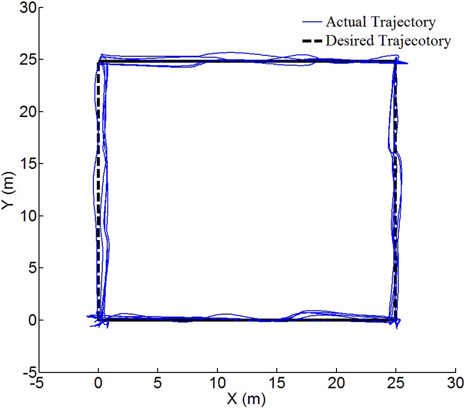
Similarly, the experiments show the average absolute deviation of 0.66 and 1.05 m for trajectory tracking using the QFT-fuzzy and ArduCopter controllers, respectively. The values of average absolute deviation for each experiment in each direction are listed in Table 4. Figures 26 and 27 show the square-shaped trajectory and the followed actual trajectory using the QFT-fuzzy and ArduCopter controllers for five experiments, respectively.
Comparison of results of five experiments using QFT-fuzzy and ArduCopter controllers.

QFT: quantitative feedback theory.

Square-shaped waypoint trajectory and followed trajectory by the QFT-fuzzy controller for five experiments. QFT: quantitative feedback theory.

Square-shaped waypoint trajectory and followed trajectory by the ArduCopter controller for five experiments.
Conclusions
In this article, design and implementation of a simple QFT-fuzzy autopilot system for a quadrotor was presented. The proposed QFT attitude controller takes the following criteria into account: (i) system stability, (ii) disturbance rejection, and (iii) reference tracking. The performance of the designed attitude controller was validated experimentally indicating the efficacy of the proposed controller in disturbance rejection and reference tracking criteria. An FLC replaced a human operator to control the position of the quadrotor and to render a robust trajectory tracking. The results obtained by the QFT-fuzzy controllers in following a square-shaped trajectory indicate a 37% decrease in average absolute deviation for position tracking compared to the results achieved by the inbuilt ArduCopter autopilot.
Footnotes
Declaration of conflicting interests
The author(s) declared no potential conflicts of interest with respect to the research, authorship, and/or publication of this article.
Funding
The author(s) disclosed receipt of the following financial support for the research, authorship, and/or publication of this article: This study was funded by Government of Canada and Natural Sciences and Engineering Research Council of Canada (RGPIN 12353-2013).