
Abstract
This paper presents a new end-effector as a key component for a robotic needle insertion-type intervention system and its kinematic analysis. The mechanism is designed as a spherical mechanism with a revolute joint and a curved sliding joint, and its links always move on the surface of a sphere. The remote centre of motion (RCM) of the designed mechanism is placed below the base of the mechanism to avoid contact with the patient's body, unlike the conventional end-effectors developed for needle insertion. For the proposed mechanism, the forward kinematics are solved in terms of input joint parameters and then the reverse kinematics are solved by using the cross-product relationship between each joint vector and a vector mutually perpendicular to the vectors. The kinematic solutions are confirmed by numerical examples.
Keywords
Introduction
The intervention procedure is a relatively new treatment using radiographic equipment such as computed tomography (CT) and cone-beam CT (CBCT), which can achieve the smallest incision and reduced tissue damage or loss when compared with traditional open surgery. The procedure includes angioplasty, opening narrow blood vessels using balloons or stents, catheterization by putting a catheter into blood vessels, tissue ablation using electrical conduction by radio frequency, biopsy for sampling dysfunctional tissue, and so forth [2, 7–12]. Among these, the last two use specified needles; thus, they are called ‘needle insertion-type interventions’. Although this intervention has the aforementioned benefits, the flexibility of thin needles and the heterogeneous properties of tissue and organs make it difficult to achieve accurate and precise needle insertion, and radiation exposure for operators is also a critical issue [13]. In order to overcome such danger and improve accuracy and precision in the procedure, robot technology has been employed.
A matter of interest in the research on robotic needle insertion-type intervention is how to adjust the pose of the needle before or during insertion. Thus, various robotic mechanisms which basically implement three degrees-of-freedom (DOFs) — two rotations for needle pose adjustment and one translation for needle insertion have been developed. The insertion of a needle-type instrument or a stick-like tool, such as a laparoscopic instrument (which is a fundamental motion in minimally invasive surgery or intervention) is through an entry point on the patient's body, and the pose of the instrument is adjusted pivoting around the entry point, which is called the ‘remote centre of motion’ (RCM). Various RCM mechanisms with different structures and components have been designed for robotic systems applied to minimally invasive surgery or intervention.
A parallelogram is a typical RCM mechanism [6, 14–17], Gimbal [1, 18] and arc [19] can also be an RCM mechanism. Combinations of double planar mechanisms [5, 20–22] and a Gough-Stewart platform-type parallel mechanism [3] have been developed as RCM mechanisms. Spatial linkages constructed by four-or five-bars could implement RCM motion by their geometries [2, 23, 24]. RCM mechanisms by the components such as belt and gear [25, 26], have been developed.
Most of these RCM mechanisms in the literature are mounted on the patient's body or the table. The patient-mounted-type systems need more careful consideration regarding sterilization and aseptic manipulation, and also measure to compensate for disturbance from the patient's unexpected movements due to respiration, coughing pain, etc. Table-mounted-type devices may not be appropriate for use in CT due to possible interference with the image-acquisition process by the added weight and motion of the device on the table. To avoid these potential drawbacks, the system shown in Fig. 1 is proposed. The robot system consists of a multi-axis robot arm for macro-or meso-positioning, an end-effector for instrument pose setting and insertion motion, and a planar mechanism coupling the arm and the end-effector to compensate for unexpected motion of the patient and active planar adjustment of the RCM location (which is used when the needle is re-inserted to correct any insertion-path error due to soft tissue characteristics). Among the components of the system in Fig. 1, the focus of this paper is the robot end-effector that places a needle using two actuators.

An example of robotic needle intervention
In this study, a two-DOF robot end-effector is introduced as a part of a robotic needle intervention system, and its forward and reverse kinematics are solved. The mechanism is designed as a serial linkage which consists of a revolute joint and a curved sliding joint, and its links always are on the surface of a sphere. The paper is organized as follows. A formal description of the mechanism to be analysed is given in Section 2. In Sections 3 and 4, the reverse kinematics are analytically solved. Numerical examples for the workspace and the forward and reverse kinematics are presented in Section 5. Finally, Section 6 discusses the conclusions.
Table 1 shows the characteristics of several end-effectors developed primarily for use in a needle insertion-type intervention. Some of them mount the end-effector on the patient, and others are mounted on a separated table or on the robot arm. The patient-mounted end-effectors are not appropriate when a target organ is affected by uncontrolled motion on the part of the patient. For example, the patient's body and the end-effector on the body move in an unexpected direction when the patient breathes in lung biopsy. The table-mounted end-effectors or those joining an articulated arm are free from such problems, but if they are kinematic mechanisms with intrinsic RCM (which means the RCM created by the structure of a kinematic mechanism), a risk of contact between the end-effector and the patient's body still exists. In the end-effectors with intrinsic RCM, such as a gimbal or parallelogram mechanism, the RCM is placed at a horizontal line passing through the base of the mechanisms or a joint linked to the base. As shown in Fig. 2, the RCM of the gimbal mechanism represented by the half circle is the entry point, and the base of the end-effector is placed on the line L g . If it is thought that the entry point is on the patient's body, a part of the end-effector always-or often-attaches to the body.
Comparison of end-effectors for needle intervention
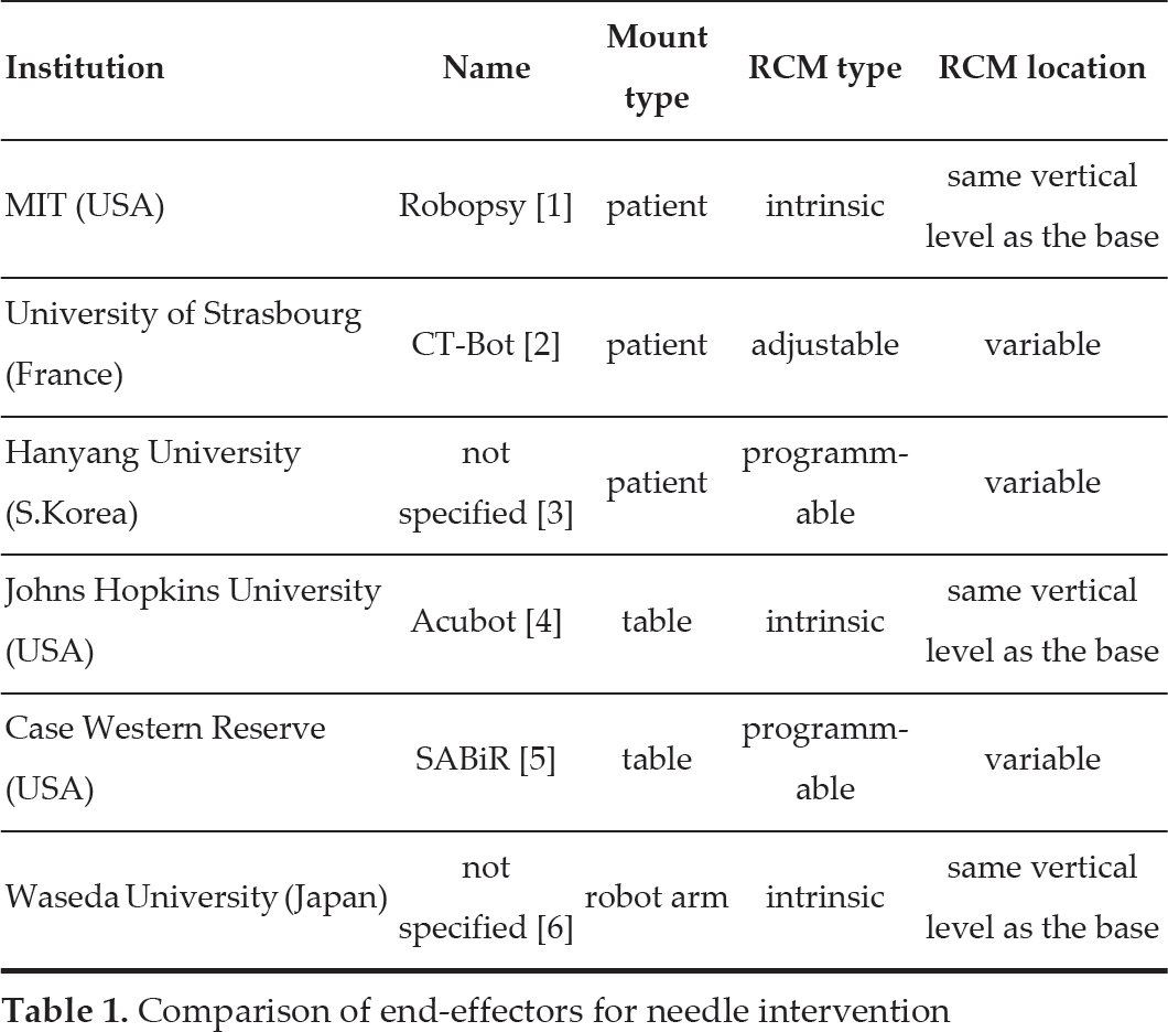
Comparison of end-effectors for needle intervention

Gap between the patient's body and the base of the mechanism
A solution to such a problem might be to design the end-effector with an RCM below the base of the mechanism. A two-DOF spherical mechanism satisfying the requirement can be designed, whereas it is impossible to design a two-DOF parallelogram.
If one axis of the spherical mechanism is designed so that a needle makes a trajectory like the arc of the angle ϕ in Fig. 2, the base of the end-effector is on the line Ls. This can give a clearance of l s from the vertical level of the entry point. Thus, one of the design parameters, ψ0 can be defined as:

where r s is the radius of the virtual sphere from the spherical mechanism.
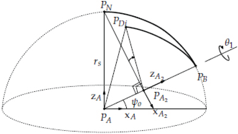
The mechanism to be considered in this paper is shown in Fig. 3. Joint 1, connected to the base of the mechanism, is located on the surface of a sphere with a radius r s . The axis of Joint 1 passes through the centre of the sphere and the angle between the axis and the equator plane-formed by the equator and the centre of the sphere-is defined as ψ0. Links 1 and 2 are curved so that they are always on the surface of the sphere. The end point of Link 2 is located at the north pole of the sphere, which is defined as the home position P H when both links have nominal lengths and both joints have nominal angles. Each joint motion is shown in Fig. 4. The angles of Joints 1 and 2 are parametrized as θ1 and θ2, respectively.

Mechanism concept

Joint motion
The forward kinematics problem is to determine the target or end-tip point of the mechanism where the values of the joint parameters are given. Therefore, the vector of the end-tip position for the reference coordinate system,pD, is expressed in terms of joint parameters θ1 and θ2 where the reference coordinate system is defined as {A}, whose origin is the centre of the sphere, and a unit vector projected from the axis of Joint 1 to the equator plane (x-axis), the unit vector perpendicular to the equator plane (z-axis), and the vector made by the cross product of the two vectors (the y-axis) are the direction vectors of the reference system.
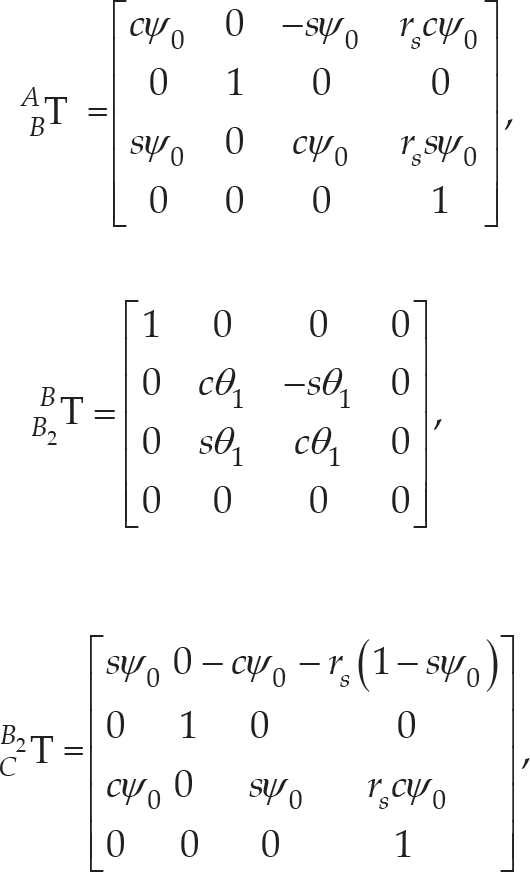
The coordinate system {B}, shown in Fig. 5, is rotated by an angle ψ0 about yA from the coordinate system {A}. The orientational relationship of {B} with respect to {A} is obtained as:
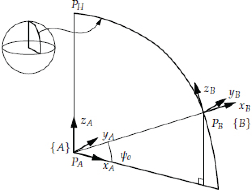
Relationship between the coordinates {A} and {B}

where c(·) and s(·) are cos (·) and sin (·), respectively. The position vector of the point P B in {A} is written as:
{B2}, shown in Fig. 6, is defined as a coordinate system which is rotated by an angle θ 1 about x B from {B}. The orientational relationship of {B2} with respect to {B} is obtained as:
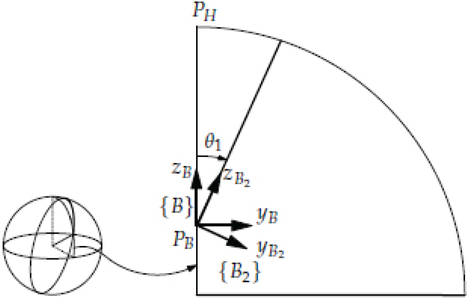
Relationship between the coordinates {B} and {B2}

{C} shown in Fig. 7, is defined as a coordinate system which is rotated by an angle −(π/2-ψo) about y B from {B2}. The orientational relationship of {C} with respect to {B2} is obtained as:

Relationship between the coordinates {B2 } and {C}

The position vector of the point PC in {B2} is written as:
{D}, shown in Fig. 8, is defined as a coordinate system which is rotated by an angle −θ2 about y C from {C}. The orientational relationship of {D} with respect to {C} is obtained as:

Relationship between the coordinates {C} and {D}

The position vector of a point P D in {C} is written as:

Therefore, the relationship of {D} with respect to {A} is obtained as:

where:
and

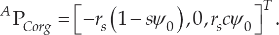
For the end point of the mechanism, where a needle is held, P D with respect to {A} can be written as:

The reverse kinematics problem is to determine two joint parameters, θ1 and θ2 in terms of the end-tip position, of which x D , y D and z D are given or known.
As shown in Fig. 9, the relation among three points can be written as:

A vector mutually perpendicular to three points


where

The plane defined by the vector

Each side of (11) can be written as:

And

where, and are unit direction vectors in the x, y and z directions, respectively. Comparing the terms for on both sides, they can be arranged as:

Regarding r s ≠ 0 in terms of design feasibility and sψo ≠ 0 by the given condition of 0 < ψ < π/2, (17) can be written as:

Meanwhile, the point P Di is on the surface of the sphere with a radius r s . Substituting (18) into the equation of the sphere:

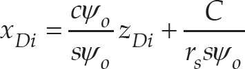
can be obtained. Arranging the terms for on both sides of (11), the equation between x Di and z Di can be obtained as:

Equation (20) can be written as:
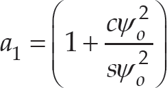
Substituting (21) into (19), a quadratic equation for z Di can be written as:

where


If the discriminant of (22) is equal to or greater than zero, two solution sets for x Di and z Di can be obtained. Between them, a physically meaningful solution satisfies either of the conditions, x D ≤x Di ≤x B or x B ≤x Di ≤x D except when (22) has repeated roots.
Accordingly,

can be obtained when y D =0, sψ o x D =cψ o z D and two points P D and P Di are on the plane shown in Fig. 9. Thus, θ2=cos(z D /r s ).
In order to find θ1 as a function of the given position, a transformation independent from θ2 can be used. First of all, the coordinate system, {A2}, whose x-and z-axes are on the plane which makes three points, P
A
, P
B
and P
N
, whose z-axis is collinear with
Two coordinate systems related to θ1

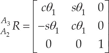
Defining the coordinate system, {A3}, whose x-and z-axes are on the plane which makes three points, P A , P B and P Di , and whose z-axis and origin are the same as those of {A2}, the rotation of {A3} with respect to {A2} can be expressed as:
The point

and the point with respect to {A} can be obtained as:

Therefore, the angle θ1 can be obtained as:

where cψo≠0 for the given condition.
The solutions for the forward and reverse kinematics obtained in the former sections are confirmed by the following numerical examples.
Workspace
The reachable workspace of the mechanism can be obtained by the result of the forward kinematic analysis in (10) and some design parameters such as link lengths, the radius of the sphere, etc. The following values are given for the parameters:

The result is shown in Fig. 11.
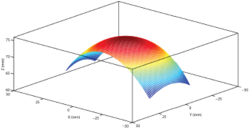
Workspace of the mechanism
This example is based on the result of the reverse kinematic analysis in (12) and (31). For two kinds of the desired end-tip motions-which are a spiral and a cross-like curve on the sphere-the aim is to obtain trajectories of the joint parameters by the kinematics while not considering the dynamics. The spiral is for checking the reverse kinematic solution within the workspace and the cross is for simulating a possible needle motion during positioning or else before inserting a needle.
The function for the spiral motion is given as:

where r s =75mm and is shown in Fig. 12. The trajectory of the needle axis for the given end-tip position is shown in Fig. 13. The red circle on the bottom can be thought of as the entry point on the patient's body, and the green circles mean P Di ′s. The joint parameters are calculated as shown in Fig. 14.
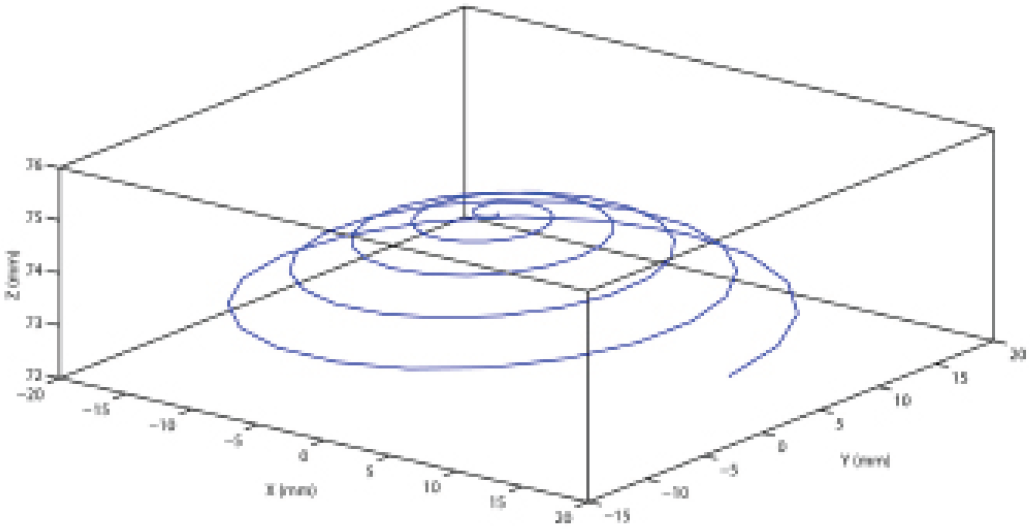
Desired end-point trajectory: spiral

Desired end-point trajectory

Joint angles for the given trajectory
Secondly, the function for the cross motion is given as:

and is shown in Fig. 15. The trajectory of the needle axis for the given end-tip position is shown in Fig. 16 and the joint parameters are calculated as shown in Fig. 17.
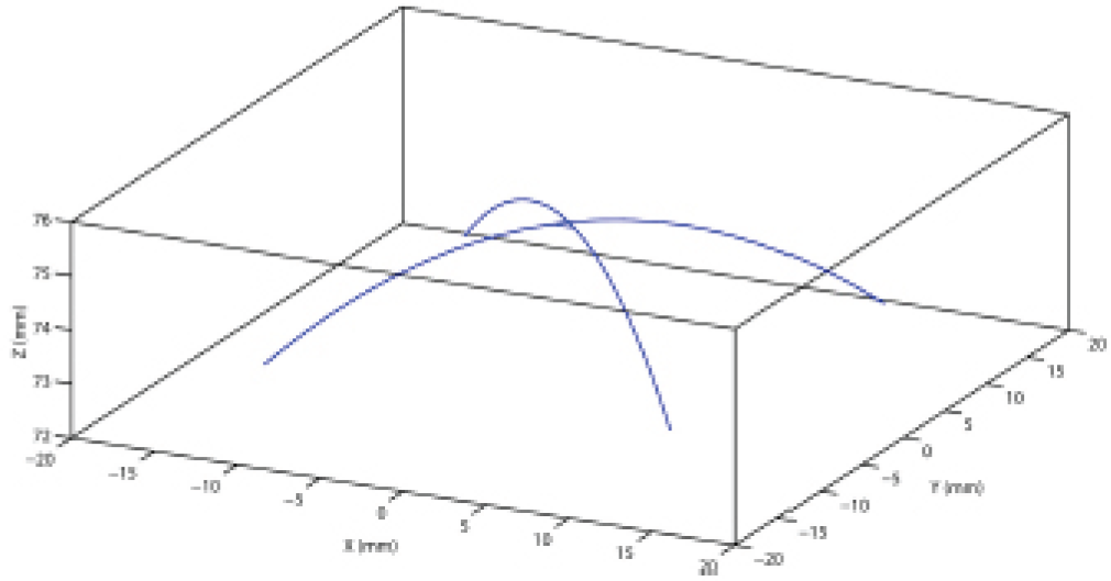
Desired end-point trajectory: cross

Desired end-point trajectory: cross

Joint angles for the given trajectory
From the kinematic model discussed in the previous sections, a conceptual design of the mechanism can be created, as shown in Fig. 18. The first link (Link 1) that can rotate by a revolute joint is designed as a body with a blank inside so that the second link (Link 2) can move along the sliding guide rails placed on both sides of the first link. Such a configuration can achieve relatively higher stiffness of the linkage compared to links connected by a prismatic joint in a series. Link 2 holds a needle or needle assembly used for a needle insertion-type intervention. The sliding guide should be designed so that the centre of Link 2 is always on the surface of the virtual sphere and the normal direction (needle axis) heads the RCM point.

Conceptual model
The angular displacement of two joints in the mechanism is an important design parameter given that the role of the mechanism is to adjust the posture of a needle. In the proposed spherical mechanism, it can be determined by the rotation angle of a revolute joint and the arc length of a prismatic joint. Another factor to be considered in the design is whether the mechanism is CT-compatible or not. The best option is to use entirely non-metallic parts to build the mechanism, but this is hard to realize because motors are necessary for the active control and some parts should be stiff enough to resist abrasion. To minimize CT metal artefact by the metallic parts, the motor, the gear that provides the sliding motion of Link 2 and base part are all placed in the rear of Link 1.
Based on the aforementioned concept, a spherical mechanism-typed end-effector model can be designed as shown in Fig. 19. Link 1 is designed as a curved U-shape to put the needle holder inside and Link 2 has gear teeth to move around the curve of Link 1 by an external gear directly connected with a motor. The range of the teeth of Link 2 is determined to cover 80 degrees out of a circle whose centre is the RCM point so that the needle holder can slide for ± 30 degrees, which is the value specified in other end-effectors. The nominal radii of the gear and Link 2 are designed as 15 mm and 111 mm, and the number of teeth of the gear and the virtual gear extended from Link 2 is 20 and 148, respectively. Therefore, a revolution of the gear corresponds to about 0.849 radians (48.65 degrees) in angular displacement of Link 2, which can be obtained by the relationship:

Designed model: (a) mechanism design, and (b) exploded view

where r g is the gear ratio determined by the number of teeth of the gears.
This paper has provided analytic solutions for the forward and reverse kinematics analyses of a robotic mechanism that could be used in a robotic needle intervention system and a design model. The mechanism is designed as a spherical mechanism with a revolute joint and a curved sliding joint, based on the RCM concept. For the forward kinematics of the mechanism, a unique solution is obtained. For the reverse kinematics, two solutions can be found but only one solution is physically meaningful. The numerical examples demonstrated the reachable workspace for the given design parameters of the mechanism and the values of the joint angles required to achieve the desired trajectory of the end-tip of the mechanism. The workspace simulation demonstrates that the concept of the mechanism-base placed at a vertically non-identical level with the RCM location was properly implemented in the spherical mechanism-type end-effector and the designed end-effector seems to meet medical doctors' needs even if it is difficult to strictly determine a quantitative measure for such needs because of clinicians' methodological differences regarding medical treatment.
Our future work will focus on the motion analysis of the total robotic system, including a planar mechanism for compensating unwanted motion during needle insertion as well as the mechanism in this paper.
Appendix
Each element of the transformation matrix representing the relationship of {D} with respect to {A} is obtained as:

where (i, j) on the left-hand side denotes the i−th row and the j−th column.
Footnotes
9.
This work was supported by the Industrial Strategic Technology Development Programme (10041618, Development of Needle Insertion-type Image-based Interventional Robotic System for Biopsy and the Treatment of a 1 cm Abdominal and Thoracic Lesion with Reduced Radiation Exposure and Improved Accuracy) funded by the Ministry of Trade, Industry and Energy (MI, Republic of Korea).