
Abstract
Sensory feedback plays a very significant role in the generation of diverse and stable movements for animals. In this paper we describe our effort to develop a Central Pattern Generator (CPG)-based sensory feedback control for the creation of multimodal swimming for a multi-articulated robotic fish in the context of neurocomputing. The proposed control strategy is composed of two phases: the upper decision-making and the automatic adjustment. According to the upper control commands and the sensory inputs, different swimming gaits are determined by a finite state machine algorithm. At the same time, the sensory feedback is exploited to shape the CPG coupling forms and control parameters. In the automatic adjustment phase, the CPG model with sensory feedback will adapt the environment autonomously. Simulation and underwater tests are further conducted to verify the presented control scheme. It is found that the CPG-based sensory feedback control method can effectively improve the manoeuvrability and adaptability of the robotic fish in water.
Introduction
In recent years, more and more bio-inspired mechatronic systems that can operate in unstructured environments robustly and efficiently have been proposed. A precondition behind this trend is that long evolved biological solutions can partially or fully be transferred to engineering systems [1]. It is widely recognized that control mechanisms in animals are governed by networks of neurons. For both vertebrate and invertebrate animals, the control of locomotion is mostly distributed, self-adapted, and occurs in real-time among multiple actuators. Of particular interest to roboticists are studies on Central Pattern Generators (CPGs) [2, 3]. In the context of neurocompting, the CPGs can be considered as a dedicated neural mechanism involving a group of neurons that generate rhythmic signals in a coordinated manner without sensory feedback, while sensory feedback is needed to shape the CPG signals. This kind of neural mechanism generally underlies the production of most rhythmic motor patterns, such as swimming, walking, and hopping. Remarkably, CPGs exhibit dynamic invariants to preserve rhythms which are flexible and robust [4–6]. Besides rhythmic motions, CPGs are extended to cover discrete motions as well [7].
Therefore, the bio-inspired CPG-based control method has been proven to be a successful attempt to deal with coordinated multi-degree-of-freedom (or multiple actuators) motion control issues.
Concerning the CPG-based robotic locomotion control, much work has been conducted on modelling analysis, parametric determination, as well as robotic implementation [4]. Regarding the feature of sensory feedback that is not required but is able to modulate ongoing motor behaviours as a response to environmental changes, coupling sensory feedback to the CPG model has been drawing increased attention. For instance, Héliot et al. utilized multisensor outputs as inputs to nonlinear observers of modified Van der Pol oscillators to estimate the overall phase of the system for a robot low-level controller [8]; Fukuoka et al. proposed a phase modulation method for a neural oscillator for a quadruped robot on the basis of the measurement of the body angle [9]; Simoni et al. integrated an internal feedback from a position encoder to a controller for a single-link rigid system based on a silicon CPG model [10]. Unfortunately, due to the complexity of the coupled CPG model and the difficulties of real-time implementation, the sensory feedback coupled CPG model has been less well investigated in fish-inspired swimming control. In particular, a systematic design method for sensory feedback control is still missing.
In this paper, we set our focus on CPG-based swimming control. Inspired by the lamprey whose undulatory motions are governed by CPGs, more recent studies use CPGs to generate the different swimming gaits. In order to improve the control system's adaptation to environmental changes, external requirements, and proprioceptive information, a two-phase CPG-based control architecture for implementing the autonomous locomotion of a multijoint robotic fish with a pair of artificial pectorals has been proposed. First, a CPG-based feedback control model to generate adaptive swimming patterns is given. Each oscillator in the CPG model only couples with its nearest neighbours. Moreover, the frequency and amplitude of the undulatory output signals of the oscillators can be modulated separately. Second, a finite state machine (FSM) algorithm is combined to determine the appropriate locomotion gait so that the CPG coupling forms and control parameters are ultimately modified. Finally, experimental results are provided to validate the CPG-based sensory feedback control method, which can be extended to other robotic applications.
The remainder of the paper is organized as follows. Section 2 provides the design and implementation of a multijoint robotic fish with a pair of artificial pectorals. In Section 3, a two-phase CPG-based control architecture is proposed, while a CPG-based sensory feedback mathematical model is analysed. The method of determining swimming gaits, and modifying the coupling forms and parameters is presented in Section 4. Experimental results are described in Section 5. Concluding remarks and directions for ongoing work are given in Section 6.
Development of the Robotic Fish Prototype
Mechatronic design
In nature, fish can perform very efficient locomotion and manoeuvring in water. Attracted by the fish's remarkable swimming feats and also driven by the desire to mimic this performance to update existing AUVs technologies, extensive theoretical and practical research has been carried out to advance this interdisciplinary field [11–13]. Robotic fish can be sorted into the anguilliform type, carangiform type and ostraciiform type according to their propulsion modes. An anguilliform robotic fish propels itself using whole body muscle movements in swimming, like an eel or a lamprey. There are many studies on anguilliform robotic fish [14–16], especially dynamical analyses and implementations of backward swimming. For example, Herrel et al. analysed forward and backward swimming kinematics in two burrowing anguilliform fishes, Pisodonophis boro and Heteroconger hassi [17]. Moreover, Niu et al. performed a dynamic analysis of an anguilliform robotic fish and implemented its backward swimming [18]. A carangiform robotic fish is able to swim using the caudal fin and swinging body connected with the tail, like the motions of salmon, tuna and swordfish. Using the swinging of the latter part of the body and the tail to propel itself, which is called BCF (body and/or caudal fin) mode, is the basic mode of fish swimming. Many studies focus on this kind of robotic fish [19–21] as it is expected that the carangiform robotic fish would have a more powerful motion capability than an anguilliform one. Some research works are relevant to CPG-based swimming control [22–24]. An ostraciiform robotic fish swims only using the tail swing without the use of the body swing. This robotic fish is mostly small in size [25].
To analyse the robotic fish dynamics and motion capability with CPG-based control, a multijoint robotic fish mimicking carp has been developed in our laboratory. The development of a robotic prototype with a CPG-based controller is illustrated in Figure 1. The swimming motion controller of the robotic fish adopted a CPG-based algorithm, which is able to generate an abundance of rhythmic activities. Both the hardware and software of the motion controller are easily upgradeable and expandable, both of which benefit from the structural design.
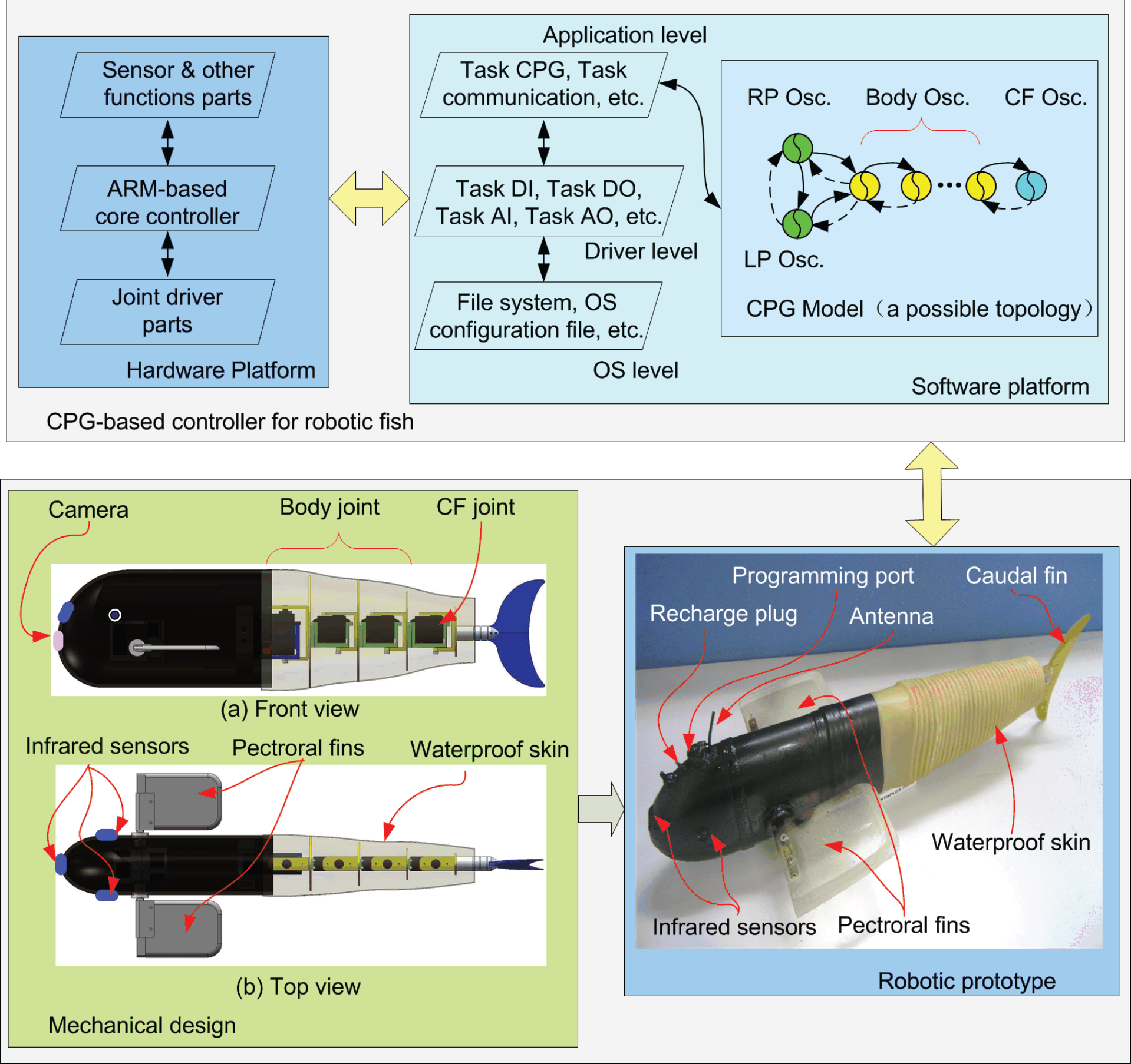
Development of the multijoint robotic fish prototype and its CPG-based controller, where “osc.” is the abbreviation of “oscillator”, “LP” is “left pectoral fin”, “RP” is “right pectoral fin”, “CF” is “caudal fin”, “OS” is “operation system”, “DI” is “digital input”, “DO” is “digital output”, “AI” is “analogue input”, “AO” is “analogue output”
Mechanically, the robotic fish is made up of four parts: an anterior body, a flexible rear body, a caudal fin, as well as a pair of artificial pectoral fins. Its head, made of fibre reinforced plastics, is rigid. In the head cavity, there are a control circuit board, batteries, balance weights and sensors. The rear body is flexible which assists in generating body wave and balancing motions.
Since the robotic fish's flexible rear body is composed of a number of segments, the oscillatory part of the robotic fish can be discretely designed as a multi-link mechanism comprising several oscillating hinge joints actuated by motors. The outside of these joints is a plastic crinkled waterproof skin. In particular, each pectoral fin, capable of 0–360° rotation via a set of custom-built gears, can be controlled independently or synchronously. To ensure a good balance between buoyancy and weight, the distribution of mechatronic components should be cautiously arranged. The technical specification of the robotic fish prototype is further tabulated in Table 1. By wirelessly modulating the oscillatory frequency and/or amplitude, various swimming speeds can be accomplished [26]. By varying the rotation angle of the left and right pectoral fins, the robot can freely pitch up and down. It means that the robotic fish can replicate highly manoeuvrable behaviours.
Technical specifications of the robotic fish prototype

Different swimming gaits (modes, or loosely termed behaviours) can be executed by physically coordinating multiple control surfaces. As will be explained in detail later, different gaits correspond to different sets of CPG parameters [27, 28]. The available swimming gaits include:
Forward swimming: in this gait, the robotic fish, like its biological counterpart, swims straight by flapping the multijoint tail to reproduce the underlying travelling waves.
Backward swimming: the robot achieves this gait with ease by artificially generating a backward propagating body wave. It is interesting to note that backward swimming is very useful for negotiating possible deadlocks in a narrow space.
Turning left: the joint with an additional angle offset will make the robot body laterally curved. When the robot body bends to the left, it will turn left with the forward (or backward) thrust mostly resulting from the lateral flapping of the tail.
Turning right: in the same fashion as the left turn, the robot will turn right when the fish body bends to the right side.
Pitching up: by setting a specific angle a for the pectoral fins between 0–90° (or −90°), the robotic fish will pitch up (surfacing) or pitch down (diving) so as to enable actual 3-D movement. Furthermore, with the depth information measured by onboard sensors, by finely tuning α, a delicate depth control becomes possible. When the pectoral fins are set to [–90°, 0] and keep oscillating, the robot will execute pitching up.
Pitching down: when the pectoral fins are set to [0, 90°] and keep oscillating, the robotic fish will obtain a descending thrust and thereby pitch down.
Notice also that except for the above defined six behaviours, the robotic fish primarily executes acceleration and deceleration.
Hardware and software design of the controller
The control hardware of the robotic fish has been designed with built-in modularity, which offers a sound guarantee for its functional expansion. It consists of five parts: an ARM-based core controller board, a joint driver part, a sensor part, a wireless communication part, and a power supply board. The joint driver part, sensor part and together with the wireless communication part are included in the main PCB (Printed Circuit Board). The ARM-based core controller board exchanges information with the main PCB by using a control cable. It is responsible for carrying out a control algorithm, generating CPG waves, and other computing tasks. To drive the joints, the joint driver part amplifies the output signals. The sensor part deals with weak signals by amplifying, shaping and transforming. The robotic fish communicates with other robotic fish or higher control centres through the wireless communication part. For the radio control of the robotic fish used in this paper, a frequency of 433 MHz is applied.
The control software of the robotic fish is implemented with a real-time operating system called μC/OS-II. It can be divided into three levels: operating system level, primary user level, and advanced user level. In the whole software, the boot loader subroutine and μC/OS-II porting codes belong to the operating system level. Interrupt service routines, task AI, task DI, task PI, task DO, and task AO are at the primary user level. Other user tasks are in the advanced user lever. Since the real-time operating system μC/OS-II is a highly portable, very scalable, preemptive real-time, multitasking kernel, all tasks are arranged to their own priorities ranging from three to 15. The functions and priorities of these tasks are described in Table 2.
Functions and priorities of the tasks

Functions and priorities of the tasks
There are two important tasks at the advanced user level: task COMM and task CPG. Task COMM is to communicate with other remote controllers by using the wireless communication module. The communication protocol includes setting up communication, refreshing CPG parameters, initializing link positions, transferring the swimming mode, adjusting the swimming speed, changing directions, setting the robotic fish ID, etc. The remote controller sends commands three times to the robotic fish. After receiving the command, the robot will answer it immediately. If one or more of the three are answered correctly, the communication is thought to have been set up successfully. The link positions and robotic fish IDs are stored in nonvolatile memory. Task CPG deals with CPGs for body and pectoral fins, and receiving the parameters set by the other tasks. It generates CPG signals online for the swimming control.
A two-phase CPG control architecture
It is important that a creature has a sensory feedback system for survival. To react to the external environment, a creature in nature will make decisions from sensory feedback. The possible sensory feedback mechanism is shown in Figure 2. The sensory feedback can occur at different levels, such as the highest centre, CPGs, motor neurons, or effectors. For example, the cerebral cortex, basal ganglia, or cerebellum can fuse information and make decisions as the highest centre. It is not true that all sensory signals are transformed to the highest centre to be dealt with. A knee jerk is a reflex response that occurs without the brain's decision. Inspired by creatures in nature, a robotic fish can be designed with a multi-layer feedback swimming motion controller.

The sensory feedback mechanism of a creature
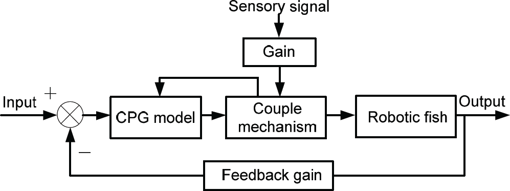
As was emphasized previously, for the adaptation of the mechatronic system to environmental changes, external requirements, or proprioceptive information, it is necessary to integrate sensory signals into the robot control loop. For a creature in nature, it adapts to the external environment with a possible information fusion and motion reaction process. To this end, as shown in Figure 3, a two-phase CPG-based control architecture for performing autonomous and multimodal locomotion is created. Specifically, the whole implementation process of the control architecture is divided into two phases: upper decision-making and automatic adjustment. According to the upper commands from the controller and the sensory input, an FSM algorithm determines locomotion gaits such as swimming forward/backward, turning left/right, pitching up/down, and further modifies the CPG coupling forms and parameters. After that, the CPG model with sensory feedback control will take charge of the autonomous locomotion control.
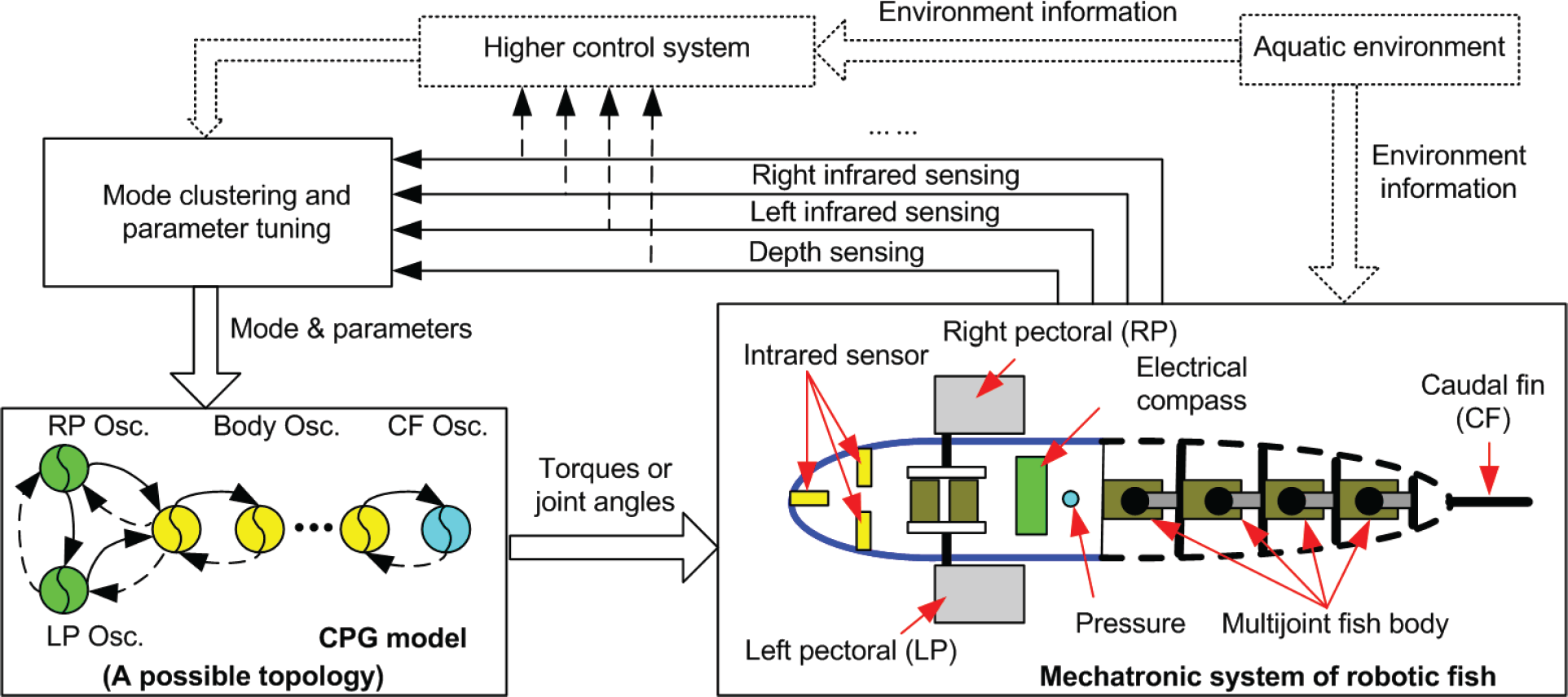
The CPG-based feedback control system for the robotic fish, where “osc.” is the abbreviation of “oscillator”
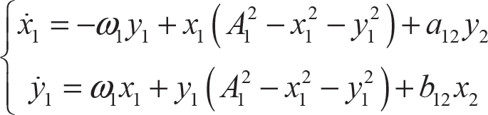
For the purpose of generating a travelling wave, a Hopf oscillator is employed as the basic rhythm generator in the CPG model [29]. Inspired by the lamprey spinal generator for locomotion [30, 31], a weak coupling scheme is adopted in this work, in which all self-couplings are removed. The whole CPG model is implemented as in the following nonlinear differential equation:

where the subscript i corresponds to the i -th oscillator (i = 2, 3, …, n–1) and n indicates the total number of neural oscillators in the CPG network. The state variables xi and yi denote the membrane and adjustment potential, respectively. ω
i
and Ai stand for the intrinsic oscillation frequency and amplitude.
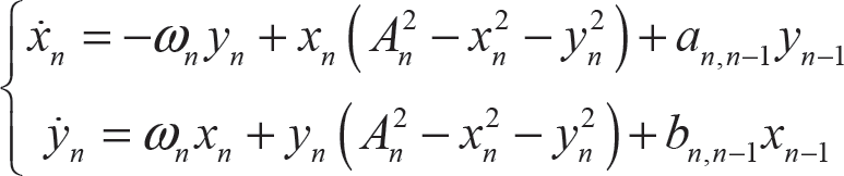
Based on (1), (2), and (3), suppose that the descending coupling weights are identical, which means the i-th CPG receives influence from the i–1-th one. That is, ai,i–1 = a1 and bi,i–1 = b1, where i = 2,3,…,n; so do the ascending coupling weights, having ai,i+1 = a2 and bi,i+1 = b2. To circumvent the calculation of the differentiators present in (1) via a microcontroller chip, a difference operation is finally performed.

where xi (k) and yi (k) are the state variables at time kΔt, and Δt is the time interval. From (4), xi (k + 1) and yi (k + 1) can be computed iteratively. This will avoid occupying a lot of computational resources owing to differentiation operations. The real-timeness of the CPG-based control system can hence be guaranteed.
A reflex action found in animals or human is known as an involuntary and nearly instantaneous movement in response to a stimulus. With a CPG model, a lower reflex model for robotic fish is proposed in Figure 4. In a lower reflex, sensory signals, such as obstacle signals, will firstly be obtained and then input into a coupling unit where the CPG output signals couple with it. This coupling mechanism is like a knee jerk reflex. In this lower reflex model, the coupling unit is not an internal part of the CPG model.
A CPG-based lower reflex model
Based on the proposed CPG model denoted by (1)–(3), a CPG-based reflex model for the robotic fish is constructed as follows.

where si is the sensory feedback variable, Λi is the feedback coefficient corresponding to si. dxi(k) denotes the increment of variable xi(k) during time Δt. t1 and t2 are the starting and stopping time of sensory output signals, respectively.
To analyse the lower reflex model, first, a CPG model with only one oscillator is analysed. As shown in Figure 5, we can assume that an obstacle sensor produces a signal at the time from 6.0 s to 14.0 s. The variable x of the oscillator with different feedbacks is plotted, where the red line denotes the value of s, the dark line represents the variable x of the oscillator, ω = 6.28, A = 1. As can be observed, when the feedback sensory signal s is positive, the oscillator produces a positive value; while s is negative, the oscillator produces a negative value. In this sense, the oscillator variable x can be used to generate turning left/right by adding it to the anterior joint of the robotic fish.

State variable x with different feedbacks s
Let us take a four-joint robotic fish as an illustration; here, turning is triggered by the lower reflex model. Let us further assume that the first joint of the robotic fish is a coupled obstacle sensory value while the other joints track normal travelling waves. When ω
i
= 6.28 (i = 1,2,3,4), A1 = 2,

CPG state variable x with s
In general, the sensory feedback control for most animals occurs at different levels, such as sensory receptors, sensory neurons, and the central nervous system or in less complex organisms, and the brain. In the CPG-based control system, one oscillator governs one joint, while coupled oscillators yield coordinated multimodal motions. A CPG-based medium sensory feedback model is shown in Figure 7. In this medium sensory feedback model, the CPG model has a built-in information fusion mechanism to deal with environment information and other external signals.

A CPG-based medium sensory feedback model
For reasons of simplicity, a case in which one sensory CPG constitutes one oscillator at the nervous system level is considered in this paper, taking the form below.
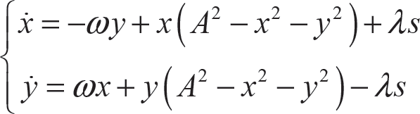
where x and y, state variables of the oscillator, and denote the membrane and adjustment potential, respectively. ω and A stand for the intrinsic oscillation frequency and amplitude. s is the sensory feedback variable, Λ is the feedback coefficient corresponding to s.
For the model denoted by (6), the feedback term Λs will affect the output signals of the oscillator. Let us consider a numerical example. When s varies from 0 to 3 or −3, then to 0, the output signal x is shown in Figures 8, where ω = 6.28, A = 1, and Λ = 1. When the absolute value of s increases to a great enough value, the oscillator will stop oscillating and produce a constant value. In practice, the oscillatory frequency, amplitude, and phase of each joint will affect the swimming speed of the robotic fish. Therefore, the introduction of external information not only affects the oscillator outputs, but also has an effect on the swimming speed. The worst case is an oscillation stop, meaning a feedback loop failure. Numerically speaking, the adopted oscillators maintain oscillation steadily under the condition of Λs ∊ (–3.15,3.15), where ω = 6.28 and A = 1.
For our four-joint robotic fish, a sensory feedback model at the nervous system level is further proposed as follows.
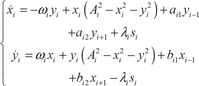
In (7), the CPG-based model consists of multiple coupled oscillators. Each oscillator integrates sensory information. Let us assume that the obstacle information is sampled and all the joints are controlled by the CPG model (7). With the same CPG parameters given in Figure 6, the outputs of an oscillator at different sensor feedback values are plotted in Figure 8. Similar to Figure 6, the positive value of the first joint will curve the fish body and lead the fish to turn right, whereas other joints (Joints 1, 2, and 3) maintain symmetrical sinusoidal trajectories.

CPG outputs of a sensory feedback model with reflex in turning motions
In complex organisms, sensory neurons convert external stimuli (e.g., vision, touch, hearing, etc.) from the environment into internal stimuli. They relay their information to the central nervous system or directly to motor neurons. Moreover, they also transmit information to the brain, the higher information centre, where the information can be further processed. Herein, to mimic the function of the brain, the two-phase CPG-based control architecture has been proposed to yield multimodal swimming. This control mechanism will enhance the swimming manoeuvrability and adaptability of the robotic fish in response to external environmental changes or proprioceptive information. A highest hierarchical sensory feedback model is proposed (see Figure 9). Like a brain, all the feedback signals and environmental information are transmitted to the information fusion and control centre.

A CPG-based highest hierarchical sensory feedback model
To illustrate the proposed highest hierarchical feedback control model shown in Figure 9, a swimming speed control method of the robotic fish is shown in Figure 10. The setting speed Vs compares with the practical speed V, and then acts as an input to a fuzzy decision and control centre. The fuzzy decision and control centre also receive the information from the vision measurement system, providing obstacle information and the swimming speed of the robotic fish. It has a fuzzy inference engine to fusion information and makes a decision. Thus, the integration of a CPG-based control, fuzzy logic, and realtime visual measurement may be a feasible solution for high-level goal-oriented tasks. Within this framework, the robotic fish will be able to accomplish goal-oriented aquatic missions. Please refer to [32] for an example of an embedded vision-guided navigation strategy for autonomous swimming.

A CPG-based highest hierarchical sensory feedback model for speed control
As a highest hierarchical feedback control centre, like a brain, the centre can not only modulate CPG parameters and other variables, but also change CPG topologies and structures. The topologies and connection weight among the CPG units are very important for a CPG network. For instance, there are three body joints and one caudal fin joint in the robotic fish in this paper. The CPG topology for the robotic fish can be one of all the topologies shown in Figure 11. More specifically, each joint is connected by two CPG units (e.g., the caudal fin joint has CPG 7 and CPG 8). That is, one CPG unit is responsible for the extensor, another is for the flexor. However, in Figures 11b, 11c and 11d, there is one joint dealing with one CPG unit which generates extension and flex. Moreover, the influence between the CPG units has two types: one is a one-direction inhibition, the other is a bidirectional influence, including inhibition and excitation. There are ring topologies in Figures 11b and 11c. The ring topology is seldom used in the actual robotic fish control schemes seen in Figure 11d.
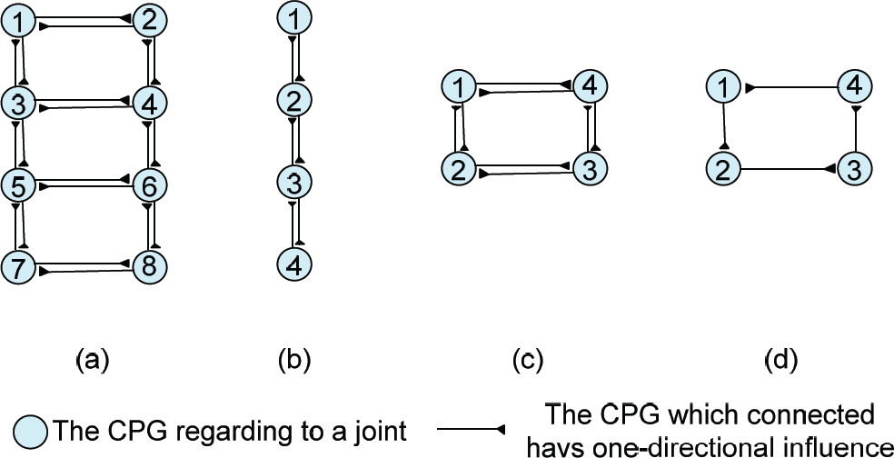
Different CPG topologies for the proposed robotic fish
The robotic fish in Figure 1 has two pectoral fins, one caudal fin and one three-joint flexible body. The robotic fish can carry out six basic swimming behaviours, including forward swimming, backward swimming, left turning, right turning, pitching up and pitching down. Each swimming mode can be executed by different CPG combinations. For example, a forward swimming motion can use the CPG topologies shown in Figure 12. In Figure 12a, the robotic fish uses the BCF plus the pectoral fins, whereas it can swim only by using pectoral fins in Figure 12c and only by using the caudal fin in Figure 12f. The robotic fish is also driven by the BCF mode with different joints in Figures 12b, 12d and 12e.

CPG topologies for the forward swimming of the robotic fish. CPG 5 and 6 are for the pectoral fins; CPG 1, 2 and 3 are for three joints in the posterior body; CPG 4 is for the caudal fin
To make a robotic fish switch from one gait to another smoothly and rapidly, an FSM method is adopted. An FSM is a mathematical behaviour model, which is composed of a finite number of states, transitions between those states, and actions, sometimes used to describe neurological systems in biology and artificial intelligence. The operation of an FSM begins with a start state, goes through transitions depending on the input to different states and can end in any of those available. Within the framework of the FSM control, the employed CPGs model, capable of individually modulating the oscillatory frequencies and amplitudes, offers multiple control options. Moreover, each state of the FSM links to one CPG topology or several CPG topologies. For instance, when a robotic fish swims forward, the CPG topology may be the one for the BCF mode, or the one for the CF mode, or the one for the PF. Differential equations of CPGs essentially function as first- or second-order filters, which can avoid instantaneous torque changes and jerky movements at the risk of damaging the motors and gearboxes. Hence, the FSM method plus a CPG model will solve the gait transition problem successfully. An FSM diagram for swimming state transition is depicted in Figure 13.

An FSM diagram for the swimming state transition
Furthermore, in order to achieve frequency adaptation, the system compares the measured speed vp with the setting speed vs of the robotic fish. The designed FSM adjusting diagram is given in Figure 14, where the values of vs and threshold variable vth are set according to the experimental data. If vp > vs + vth, the system will force the frequency to a gear that will shift up. After a specific delay, the gear will carry out the shift-up action if vp > vs + vth yet. Otherwise, the gear will maintain the original state. Once vp > vs + vth at the time, the system will go into the steady state immediately. If vp < vs – vth, like the shift-up process, the control system will shift down its frequency gear. As a consequence, a smooth speed adjustment results.
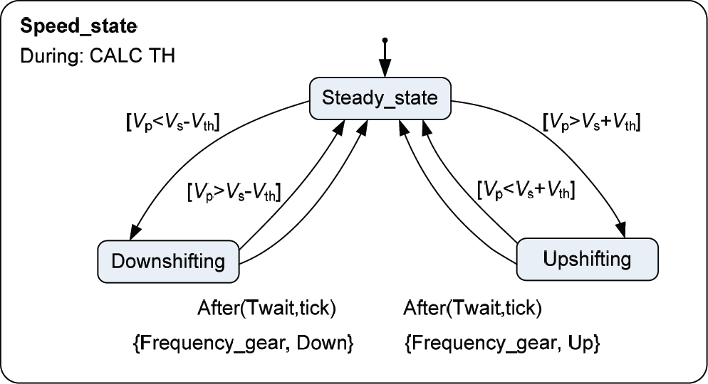
An FSM diagram for speed adjustment
To evaluate the proposed CPG-based sensory feedback control method, in-lab and field tests on the multimodal swimming of the robotic fish have been performed. Some typical swimming scenarios are shown in Figure 15. Specifically, with the onboard infrared sensors, the robotic fish could detect obstacles located at the front, left and right of the fish head. The obstacle-related sensory information was then coupled into the CPG control model to autonomously trigger a gait transition. Within our proposed two-phase CPG-based sensory feedback control model, if the robotic fish detected the wall of the pool, the gait of turning would be initiated (see Figure 15e). By undulating the pectoral fins with different balance positions, the robot pitched up and down freely (see Figures 15c and 15d). If the robotic fish encountered a corner, it executed swimming backwards with pectoral fins reciprocally oscillating at 180° so as to remove itself from the difficult situation (see Figure 15b). As mentioned above, the purpose of the CPG-based sensory feedback control is to offer a bio-inspired control mechanism to mimic the animals’ neural control processes and to eventually enhance the motion capabilities of the robots. A snapshot sequence is further shown in Figure 16, where the robotic fish only received an obstacle signal. The highest hierarchical feedback control centre changed its CPG topology from the BCF mode to the PF mode. Then the robotic fish swam backward only with pectoral fins so as to avoid obstacles. The overall swimming trajectory is plotted, demonstrating that the robotic fish achieved good smoothness and adaptability to switch between different swimming behaviours.

Snapshots of multimodal swimming during tests
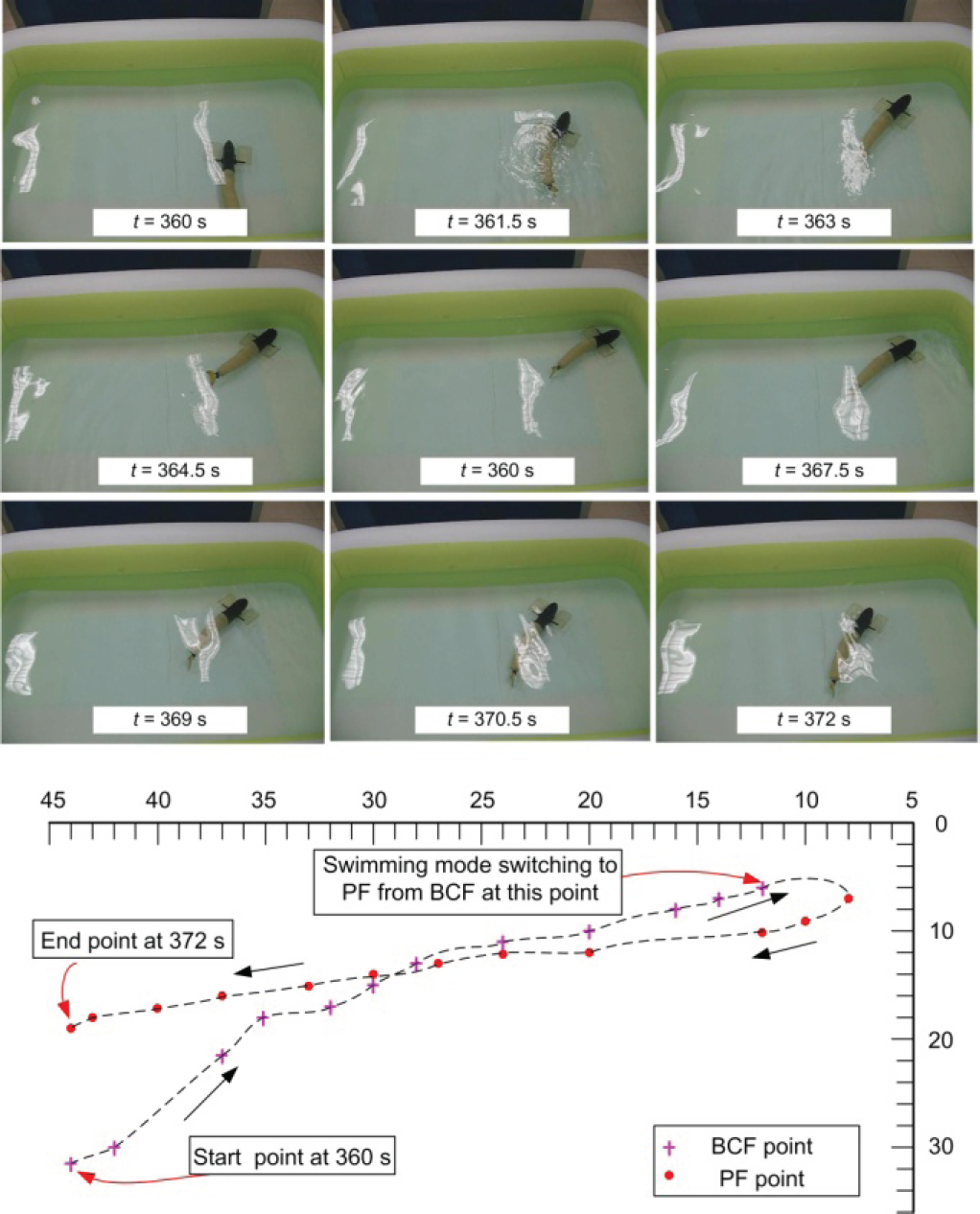
Snapshots of gait transition of the robotic fish and its swimming trajectory. Each point denotes the label position of the robotic fish. The time interval is 0.5 s.
In this paper, we incorporate sensory feedback into the CPG control loop and further discuss the model formed at lower, medium, and higher levels, respectively. The obtained results show the robotic fish governed by the sensory feedback coupled CPG model can carry out multiple types of swimming, and switch between them autonomously and smoothly. In essence, the produced swimming behaviour is a result of the interaction between the robot, the neural control system, and the aquatic environment. Thus, we should consider this problem in a more synthesized way. One limitation of the model is that only relatively simple CPG coupling and sensory information are utilized. In addition to model applicability, external disturbances (e.g., reflective waves and water flow related factors) are not taken into account in the model analysis. More extensive, stricter experiments, particularly in the field, are also required to validate the control architecture formed here so as to expedite real-world applications of the robotic fish as an effective underwater mobile platform.
We have developed a two-phase CPG-based sensory feedback control framework to achieve more manoeuvrable and adaptive swimming for a multijoint robotic fish in this paper. The proposed CPG-based gait generation approach with explicit frequency and amplitude modulation, not only achieves rather smooth transitions between gaits, but also demonstrates fair adaptation to interactive swimming. Specifically, the control procedure is further resolved into the upper decision-making and the automatic adjustment, facilitating a subsequent advanced motion planning as well as an extension. Preliminary test results have verified the effectiveness of the formulated control methods.
In the near future, we will concentrate on improving the environmental sensing capabilities of the robotic fish in the field. Other work will include the further optimization of the mechanical design and the CPG characteristic parameters so as to find widespread use of the general CPG-based sensory feedback control framework and the robotic fish for real-world applications.
Acknowledgements
This work was supported in part by the National Science Foundation of China (61375102, 61273326), in part by the Beijing Natural Science Foundation (4122084, 3141002), in part by the Excellent Young and Middle-Aged Scientist Award Grant of Shandong Province of China (BS2013DX018), and in part by the China Postdoctoral Science Foundation (2012M521337).