
Abstract
The micro/nano positioning field has made great progress towards enabling the advance of micro/nano technology. Micro/nano positioning stages actuated by piezoelectric actuators are the key devices in micro/nano manipulation. The control of piezoelectric actuators has emerged as a hot topic in recent years. Piezoelectric materials have inherent hysteresis and creep nonlinearity, which can reduce the accuracy of the manipulation, even causing the instability of the whole system. Remarkable efforts have been made to compensate for the nonlinearity of piezoelectric actuation through the mathematical modelling and control approaches. This paper provides a review of recent advances on the control of piezoelectric actuators. After a brief introduction of basic components of typical piezoelectric micro/nano positioning platforms, the working principle and modelling of piezoelectric actuators are outlined in this paper. This is followed with the major control method and recent progress is presented in detail. Finally, some open issues and future work on the control of piezoelectric actuators are extensively discussed.
Keywords
Introduction
In the 1980s, the invention of STM (Scanning Tunnelling Microscopy) [1] and AFM (Atomic Force Microscope) [2] made it possible to observe and operate atoms at the micro/nano level, and led people into the micro/nano world. Micro/nano positioning platforms play an increasingly important role in the domains of mechanics, biology, materials, physics and chemistry. Typical applications touch lithography, scanning probe microscopy, space flexible manipulators, ultra-precision machine tools and so on [3–6]. Piezoelectric actuators (PEAs) are widely applied in micro/nano positioning platforms, because of their high hardness, fast response and other outstanding features. Extensive research on the control of PEAs has been conducted, making gratifying achievements in recent years.
Unlike the general electromagnetic drives which have obvious drawbacks, such as power consumption, heating and large noise, a PEA is a form of micro-control electromechanical system. It relies on the piezoelectric effect with some crystals such that, when an electrical field is applied to the crystal, it creates mechanical stress in its structural lattice, which can be translated into movement at a micrometre or nanometre scale. Generally, PEAs exhibit six main advantages [7–8]: (1) no need for a rotating mechanism, (2) ultrahigh precision positioning (to subnanometre level), (3) instant response (to microsecond scale), (4) very large output force (typically about several KN), (5) low power dissipation, and (6) small size, solid body and convenient for design. However, the drawbacks of PEAs are also obvious. There are three major issues: hysteresis, creep and vibration. As a result of the hysteresis characteristic, the piezoelectric actuator will produce a 10–15% error of the full range under an open-loop control system [7]. With the increase of the input signal frequency, the error will even reach 35% [9]. Creep can be ignored in most cases where short lasting durations are involved. In addition, vibration problems can be reduced as much as possible through the design of the mechanical structure or damping controller. Hence, the creep and vibration are not discussed in this work. As a dominant issue, hysteresis is the main focus of this article.
In the remaining parts of the paper, Section 2 gives a brief introduction about the piezoelectric micro/nano operation platform. Section 3 mainly presents underlining principles and mathematical modelling of piezoelectric actuators. Section 4 provides a detailed review of popular control algorithms. Finally, a summary of discussion and future works are provided in Section 5.
PEA-actuated micro/nano positioning stage
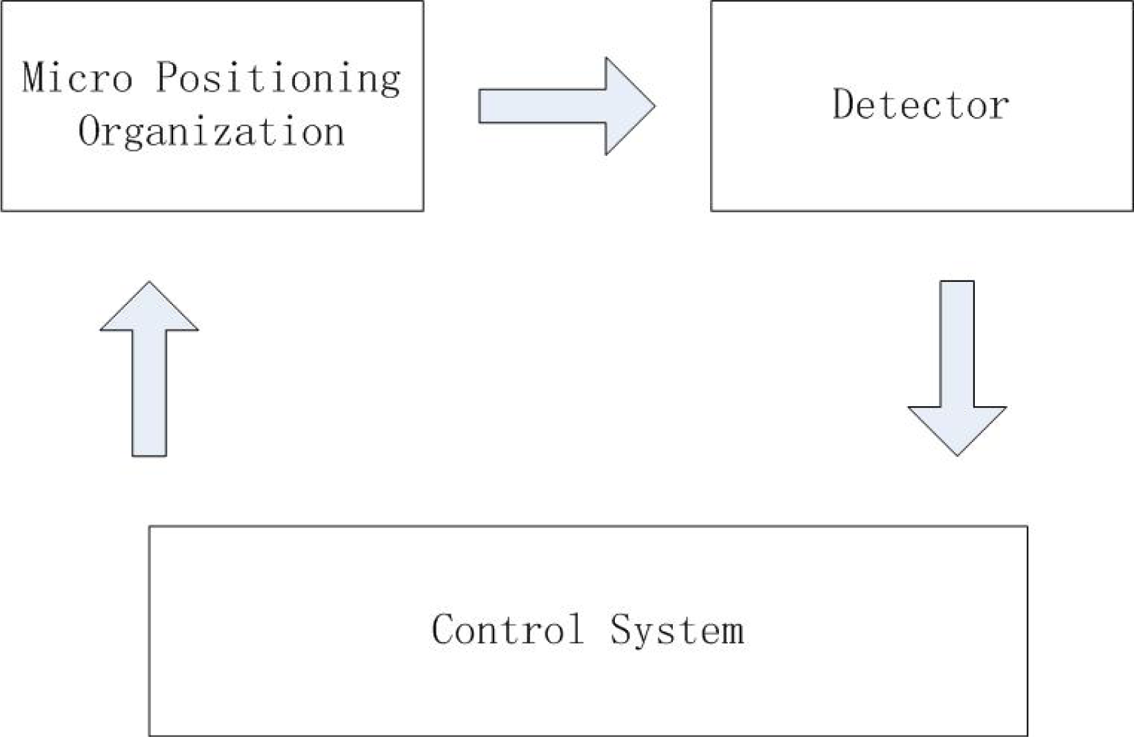
As shown in Figure 1, generally, a micro/nano positioning stage system is composed of three main parts: micro positioning mechanism, detector and control system [9].
The micro positioning mechanism is the centre of the system. It includes an actuation element and motion transmission element. The actuation element can transform electric energy or other forms of energy into the corresponding displacement and force. The transmission element then amplifies, shrinks or changes the direction of these displacements and forces.
Block diagram of micro/nano positioning system
The motion detector basically includes a displacement sensor and hardware circuit. It can measure the output displacement and feed it back to the control system for close loop control. It is also a very important component because the performance of the detector will influence the system's accuracy directly.
The control system is the command centre. It can control the stage via the control algorithm so as to make the stage work in a desired way.
Owing to the advantages of the flexure mechanism, micro/nano positioning systems which use a flexure hinge as the transmission mechanism and piezoelectric actuator as the actuating unit has been widely applied in recent years. Here is a brief introduction of this type of micro/nano positioning stage in terms of the degree of freedom (DOF).
A four-bar linkage mechanism for single-DOF positioning is shown in Figure 2. Part I and part II are connected together though the flexure hinges A, B, C, and D. Part I and II can move relatively via the deformation of flexures A, B, C, and D. This stage is simple, while the cross-coupling influences the system's accuracy.

Four-bar linkage mechanism
To eliminate the cross-coupling of two working axes, researchers designed the 2–DOF four-bar linkage mechanism. Gao [10] has designed a large displacement and high resolution stage (see Figure 3) by using the principles of two-stage amplification and double four-bar linkage mechanisms. Li and Xu [11] have created a new decoupled parallel micro/nano positioning stage using different kinds of flexure hinge mechanism. Xu [12] invented a large-stroke parallel-kinematic by proposing a new design of multistage compound parallelogram flexure. However, the increasing of internal stress on the flexure hinges will reduce the performance of the system.
3-DOF micro/nano positioning stage
In order to improve the platform positioning ability and mobility, Hwang et al. [13] have designed a stage which combines a translational motion part and rotational motion part as decoupled serial kinematics on the same plane. As shown in Figure 4, the XY stage supports the centred Θ rotate stage.

Double lines of four-bar linkage [10]

A 3-DOF positioning stage with translational motion and rotational motion [13]

Three degree-of-freedom parallel flexure mechanism [15]
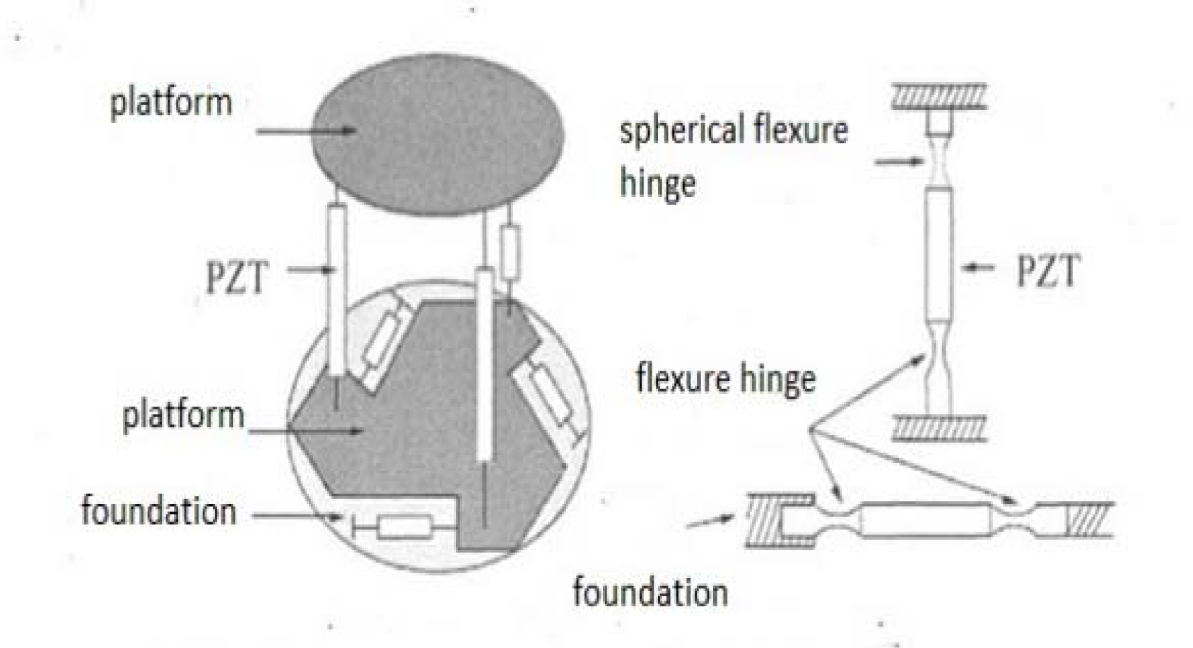
In addition, Ryu designed a 3-DOF parallel x-y-Θ micro/nano positioning stage [14]. This stage is actuated by three PEAs, which are located 120° from each other. Controlled by these three PEAs, the system can realize three DOF movements. Sugihara [15] uses it in a subnanometre laser engraving system. Figure 5 shows the work principle of this mechanism.
A parallel mechanism employs the parallel connection of several branches of flexure hinge chains between the movement platform and fixed platform. A 6–DOF platform's principle is shown in Figure 6. This stage can realize six DOF positioning. It is controlled in any combination by six motors, each having a ground abutment. However, the structure is too complicated to control accurately.
Six degree-of-freedom parallel mechanism [66]
Fundamental and background
The piezoelectric effect is a fundamental process involving electro-mechanical interactions and represents the conversion of energy. It relates the electric field to the mechanical compression/elongation in a piezoelectric material. This fundamental property of piezoelectricity has, therefore, led to the utilization of such materials in the fabrication of various piezoelectric devices, such as actuators, sensors and transducers [16–17].
Generally, piezoelectric actuators are fabricated by piezoelectric ceramic materials, which includes the lead pb(Zr,Ti)O3 crystal, commonly called PZT [18]. Figure 7 shows the polarization process for a piezoelectric actuator. In Figure 7(a), the electric dipoles of ceramic materials are oriented randomly. This does not have the function of piezoelectricity in the absence of an applied electric field. Otherwise, the electric dipoles will align themselves in a direction close to the applied electric field, and also the crystals will expand in a direction close to that of the applied electric field. The process is called polarization and is shown in Figure 7(b). When the electric field is removed, the electric dipoles will not return to the original position. This is called remnant polarization. When the electric field is applied again, the ceramic material elongates, thereby elongating the actuator (see Figure 7(c)) [19].

Polarization process for a piezoelectric actuator [19]
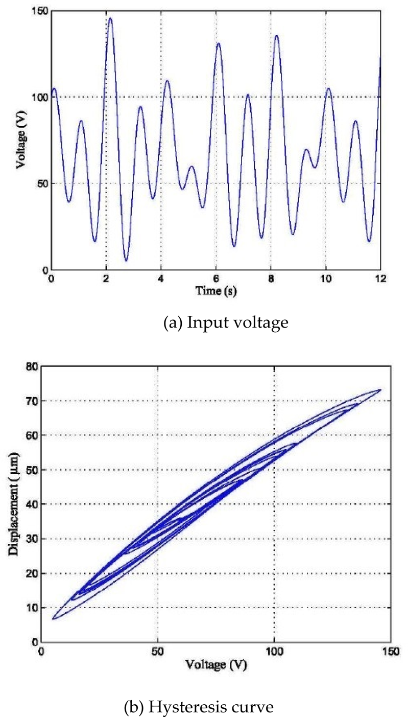
Piezoelectric ceramic actuators achieve the purpose of mechanical movement y using the inverse piezoelectric properties of piezoelectric materials, which will generate shape change with the input of voltage or current. The micro/nano level movement is what we need. However, piezoelectric actuators have a complicated hysteresis nonlinearity relationship between the input signal and the output displacement [20–22]. The hysteresis effect is shown in Figure 8.
As compared with traditional nonlinear characteristics, hysteresis nonlinearity has some special features. First, the multi-valued mapping, which means given the same input signal, the output will be different if there is no system history output state as a reference. In order to determine the output of the system, we should consider both the input signal and the history state of system, it has memorability. Besides, when the direction of the input change rate transforms, the output signal shows non -differentiable characteristics. So, we cannot expound hysteresis nonlinearity characteristics in a traditional analysis way. Extra study shows that the output signal is also dependent on the frequency of the input signal [23–24]. In addition, the hysteresis curve will broaden when the input signal rate is increased (see Figure 9).

Hysteresis nonlinearity will cause conspicuous error. Hence, it significantly influences the application of the micro/nano positioning platform [25]. In general conditions, PEAs produce 10–15% hysteresis error with respect to the full measurement range. When the rate of the input signal is increased, the error will even reach up to 35%. Moreover, hysteresis nonlinearity is the inherent attribute of PEAs, and it is a kind of hard nonlinearity. Some common linear control methods cannot solve the control problem of a hysteresis nonlinearity system effectively. Therefore, the modelling and compensation of the hysteresis nonlinearity of PEAs is always a challenging program in control design.
To this end, in order to improve the control precision of a PEA system and to meet the requirements of micro/nano manipulation, all we need is the control theory and method for hysteresis compensation of the hysteretic nonlinear system. The following discussions provide a review of the current popular modelling and control method, and summarize some new progress in recent years.
“HYSTERESIS” comes from Greek, and means a kind of ‘come from behind’ phenomena, Scottish physicist Alfred Ewing defined it as “when there are two quantities M and N, such that cyclic variation of M, then if the changes of M lag behind N, we may say that there is hysteresis in the relation of M an N” [26]. Madelung summarized the hysteresis nonlinearity characteristic, and created the famous “Madelung rules”, which is shown in Figure 10.

Schematic representation of Madelung rules [26]
Madelung gave three rules as follows [27].
Any curve CI emanating from a turning point A of the input-output graph is uniquely determined by the coordinates of A.
If any point B on the curve CI becomes a new turning point, then the curve C2 originating at B leads back to the point A.
If the curve C2 is continued beyond the point A, then it coincides with the continuation of the curve C, which led to the point A before the C1-C2-cycle was traced.
The above rules are referred to as Madelung's rules.
In order to describe this complicated hysteresis nonlinear characteristic clearly, Mayergoys presented a general definition. He explained hysteresis nonlinearity as a hysteresis transducer, which can show the relationship between input and output. As shown in Figure 11, x(t) is the system input, f is the hysteresis transducer, and y(t) is the output. Specifically, f must satisfy the following relations:

where M[0,T] is the continuous monotonie function space, n0 is the original state.

A hysteresis system
Traditionally, the modelling of hysteresis nonlinearity characteristics is a difficult problem, and there is no unique model. Researchers have developed a lot of models for describing the hysteresis nonlinearity characteristic so far, which can be separated into two main types: physics-based models and phenomenological models. Figure 12 shows the classification diagram.

Classification of different hysteresis models
Based on describing the basic physical principle of materials, physics-based models try to establish the hysteresis model through the relationship of energy, displacement and so on [28–30]. It is difficult to build physics-based models in that the physical features of a hysteresis system are always very complicated. On the other hand, the physics-based model of one hysteretic system usually cannot be applied in another system. So, the physics-based model lacks generality.
Starting from the characteristics of the hysteresis curve, phenomenological models try to describe the hysteresis curve by using the effective mathematical model directly. There is no need to pay attention to the physical meaning, while developing a new chapter of the compensation and modelling. Based on the different mathematical explanation type, phenomenological models can be classified as differential-equation-based hysteresis models and operator-based hysteresis models. A lot of references have explained them insightfully [31–38]. So, the details are not discussed in this paper.
Hysteresis compensation control theory and method
The excellent properties of piezoelectric ceramic micro-drive greatly improve the performance of traditional driving mechanisms. However, the inherent hysteresis nonlinearity of piezoelectric ceramic actuators degrades the precision accuracy of the system, causing system shock or even leading to instability of the control system. Although charge-controlled modulation has proven to be a better way to suppress the hysteresis nonlinear effect of piezoelectric ceramic actuators, the design complexity and high cost of charge amplifiers restrict their wide application. The voltage control method is still the most popular method for the application of piezoelectric ceramic actuators. The purpose of motion control of piezoelectric ceramic driven micro/nano positioning platforms is to find a way to eliminate the hysteresis nonlinearity's impact on system performance.
model
One intuitive and effective way of hysteresis suppression is to establish an inverse hysteresis model, cascade it with the controlled plant to carry out feed-forward compensation [39–41], as shown in Figure 13. Thus, by passing through a cascading combination of an inverse model and a piezoelectric actuator, the system can be considered as a linear one. In order to achieve this goal, scholars all over the world have conducted a lot of studies and they have built various hysteresis models or inverse hysteresis models for the compensation. Ge and Jouanch [7] provided a numerical inverse based on the Preisach model to linearize hysteresis nonlinearity, and a PID closed-loop control was added to improve tracking accuracy. Based on the same train of thought, Song et al. [42] adopted the traditional Preisach model and lag-lead controller to compensate for the major-circle and minor-circle hysteresis nonlinearity simultaneously. Based on the Preisach model, Croft et al. [39] provided the best feed-forward compensation control strategy and they added a PD control to improve the scanning accuracy of the piezoelectric actuator in the follow-up use of atomic force microscopy. Teang et al. [43] adopted an iterative learning control strategy to solve the Preisach model's inverse compensation control issue. Hu and Mrad [44] provided the feed-forward compensation control based on an inverse recursive form of the Preisach model. Tan and Baras [45] employed the adaptive method to establish an inverse Preisach model.

Block diagram of inverse hysteresis compensation
Generally, it is difficult to setup the analytical inverse Preisach model, although this model is widely used to establish the inverse model for compensating hysteresis nonlinearity. The Prandtl-Ishlinskii (P-I) model has the advantages of being a distinct inverse model, so it is increasingly popular in inverse hysteresis control. Krejci and Kuhnen [45] expressed the inverse analytical expression of the traditional P-I model, which reduced the tracking error by one order of magnitude. Kuhnen [46] inserted an operator dead zone into the traditional P-I model in order to describe asymmetry hysteresis nonlinearity by eliminating the influence of asymmetry on the system. Based on this controller, Shen [47] designed a new synovial controller to further improve the accuracy. Using different kinds of envelop function, Al Janaideh [48] derived the general form of the P-I inverse model.
Both the Preisach model and the P-I model are mathematically complicated, so they have many complex problems in the process of calculation and identification when they are applied in inverse control. Tao and Kokotovic [49] tried to overcome the hysteresis nonlinearity by establishing segmented and linearized self-adaptation control, then creating a self-adaptation control for the whole serial system. Rakotondrabe [50] designed a kind of inverse hysteresis compensation controller based on the observer technique. Xu [51] established an inverse hysteresis model, which uses the support vector machine model for compensating the hysteresis nonlinearity of piezoelectric actuators, subsequently proving that it is more effective than the Bouc-Wen model and the P-I model via experimental studies.
Relatively, it is hard to obtain the inverse model. In addition, the control method based on the inverse hysteresis model is simple and intuitive, but it has many drawbacks, such as heavy computation and complicated system structure. So, the calculation burden is the main issue in this type of control method.
Researchers have tried to design a closed-loop controller for compensating hysteresis nonlinearity directly, so as to replace the inverse hysteresis compensation control approach. The PID control is widely used because of its simple construction [52]. Tan [53] proposed a learning type of PID controller, and tried to enhance the robustness of the system.
On the other hand, one can consider the hysteresis item as a bounded disturbance, and reduce the hysteresis nonlinearity influence in the system by designing a nonlinear tracking controller based on the principle of sliding-mode control [54], etc. From the insightful research on the Backlash-like model, Su et al. [55] solved the robust control problem of backlash-like hysteretic nonlinear systems creatively, and then proposed a robust adaptive control scheme for the whole system's stabilization by using the P-I model. However, this kind of control method has a big disadvantage in that it relies on the requirements of the model too much. Currently, only part of the model can use this method. How to broaden the application of this type of control method is an emerging topic.
Control of PEAs
Researchers have conducted a lot of research on the control of PEAs using both classical control theory and modern control theory [56]. Essentially, there are several popular kinds of control methods as follows.
Open-loop control of PEAs
Open-loop control schemes are usually employed in applications in which position feedback is difficult to implement due to mechanical constraints [57]. As shown in Figure 14, this control method has a simple structure, and it is convenient to implement. However, its disadvantages are very obvious, such as its low precision and weak anti-disturbance ability. What is more serious is that this control method cannot reflect and solve hysteresis nonlinearity. The best solution to this problem includes introducing feedback into the control schemes, which is discussed in the following sections.

Schematic of the piezoelectric actuator model. For an input V, the output is given by g[H(v)]. The structural vibrations and some of the apparent rate-dependence in the hysteresis effect are captured in a linear model g and the hysteresis nonlinearity H is captured, using, e.g., a rate-independent Preisach hysteresis model [57].
Feedback control is a typical type of closed-loop control (see Figure 15). The hysteresis and creep nonlinearities of PEAs are open-loop characteristics, so their influences can be effectively eliminated using the closed-loop method. Nowadays, the commonly used closed-loop controls are PID control and Intelligent PID control. The feedback control changes the eigenvalue and eigenvector of the system, drives the pole moving into the correct locations that we need, and then improves the system's dynamic and static performance [58–59]. This leads to great suppression of the unknown effects including model errors, external loads and changes in the dynamics of the PEA, as well as significant improvement in position control performance. Hence, they are widely used.

Feedback control scheme, using the positioner dynamics modelled in Figure 14
The indispensable problem of this kind of closed-loop control system is that they have low gain margins, which is largely due to the quick phase loss near the first resonant peak in the frequency response of PEA [60].
The use of feed-forward can lead to improved output-tracking performance in SPM [61]. Such feed-forward is usually augmented with the feedback controller (see Figure 16) to achieve perfect tracking of the desired output.
Another control scheme which involves feedback and inverse model-based feedforward is shown in Figure 17. This feedback controller can be designed to reduce the uncertainty in the closed-loop system [62].

Combination of feedback with feedforward control [1]

A feedback controller is used for nonlinear suppression whist a feedforward controller is the inverse model of the closed loop system for cancelling out the dynamic of the closed-loop system, which can be treated as linear [1]

Comparison of open-loop and feedforward tracking of a sine wave up to 10 000 cycles at a signal frequency of 20 Hz [7]

Comparison of a regular PID controller and a PID controller with a feedforward loop for tracking a sine wave up to 10,000 cycles at a signal frequency of 20 Hz [7]
In previous work, Ge [7] compared the different control methods through experimental studies under the sinusoidal input signal. The results are shown in Figures 18 and 19. It is found that the feedforward tracking control is more accurate than open-loop control, and a PID controller with feedforward loop is significantly better than other approaches.
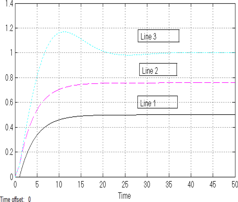
Comparison of open-loop, feedforward and PID control with feedforward compensation at a step signal
When the input signal is a step signal, the different responses of the open-loop control (line 1), feedforward control (line 2) and PID controller with a feedforward loop (line 3) are shown in Figure 20. Obviously, a PID control with a feedforward loop can provide a more accurate response than the other two methods.
The main challenge in feedback control design lies in performance improvement while maintaining the stability of the overall system in the presence of parameter uncertainty and high-frequency vibration modes. Therefore, advanced control techniques have been applied to improve the precision and bandwidth of piezoelectric actuators used in micro/nano positioning applications [63].
The modelling error, parameter uncertainty and the changes to the system's environment will result in differences between the desired and real situations. An effective way to solve this problem is to use model reference adaptive control. This kind of control does not need to know the order number and the pole of the system, as it enhances the robustness and adaptability of the controller in order to improve the control performance of the system [64].
Essentially, two main types of intelligent control have been widely used, i.e., fuzzy logic control and neural network control. Researchers have encountered significant challenges in active vibration suppression using the traditional control method. Therefore, intelligent control attracts great attention. The characteristics of fuzzy control are that it can use subjective experience and intuition. It provides a new idea in solving complicated system control problems. In addition, the neural network can approximate the continuous function in arbitrary precision. It has learning and adaptive ability. It is able to conduct a large number of operations quickly. So, the neural network control has a great potential in the identification and control of nonlinear and uncertain systems, especially in active vibration control [65].
Conclusion and outlook
This article provides a general review on the control of the piezoelectric actuator over the past decades. The main focus is to introduce the progress of PEA control that has been made in recent years in academia. Through the overview, it is found that although great progress in the development of PEA control has been made, there are still a lot of shortcomings that need to be overcome, which are outlined as follows.
How to simplify the mathematical model, optimize the control structure and reduce the error to improve stability is always the main problem in control design. Particularly, in recent years, the emerging intelligent adaptive control in combination with powerful computer processing ability is an encouraging way to improve control performance.
The generality and applicability of hysteresis models. A model, which is applicable to one system, usually cannot be applied to other systems. This results in extensive resource consumption. Therefore, the development of a comprehensive description model for various kinds of hysteresis nonlinear system is a promising area of research.
This article mainly considers the hysteresis characteristics. However, piezoelectric actuators also have vibration characteristics and creep properties. How to consider these features together at the same time to design the control system remains a big challenge. In the future, the creation of a simple structure, which can easily be combined with the other characteristics of piezoelectric actuators, is also a meaningful research direction.
Footnotes
6.
The work was support by the Macao Science and Technology Development Fund under Grant No.: 070/2012/A3 and the Research Committee of the University of Macau under Grant Nos.: MYRG083 (L1-Y2)-FST12-XQS and MYRG078 (Y1-L2)-FST13–XQS.