
Abstract
A cotton-like ZnO/SnO2 nanocomposite was grown by the carbothermal evaporation of a mixture of ZnO and SnO2 powders at 1100°C by the vapour-liquid-solid process, in which the Sn particles produced by the reduction of SnO2 act as the catalyst. Field-emission scanning electron microscope images suggest that the composites are made of microfibre-nanowire junction arrays. The structure is formed due to the fast growth of the ZnO microfibre and the subsequent epitaxial radial growth of the ZnO nanowires with Sn particles at the tips. The photovoltaic performance of the ZnO/SnO2 nanocomposite sensitized with a D35-cpdt dye was investigated. A dye-sensitized solar cell (DSSC) with a ZnO/SnO2 nanocomposite photoanode based on a cobalt electrolyte achieved a solar-to-electricity conversion efficiency of ~0.34% with a short circuit current (JSC) of 0.66 mA/cm2, an open circuit voltage (VOC) of 870 mV, and a fill factor (FF) of 59. The results show the potential of this one dimensional structure in cobalt electrolyte-based DSSCs; the further optimization which is needed to achieve higher efficiencies is also discussed.
1. Introduction
Over the past decade, one-dimensional (1D) ZnO nanomaterials have been extensively studied, since both their functional properties and highly controllable morphology make them important building blocks for understanding nanoscale phenomena and in achieving nanoscale devices [1,2]. ZnO nanostructures with various morphologies, such as nanobelts, nanowires, nanotubes, nanocombs and nanorings, have been synthesized, and in the area of optoelectronic devices, such as transparent semiconductor electrodes, light emitting transport conductors, solar-electrical energy converters, and chemical and gas sensor devices, they are attracting great interest and attention [3–9]. Though, in recent years, the fabrication of simple oxide nanostructures has progressed significantly, the synthesis of binary oxide 1D nanostructures remains a challenge, as neither the fundamental growth behaviour nor their properties are well understood. The improvement of properties and the discovery of new functionalities are key goals that cannot be realized without a better and a thorough understanding of the preparation methods. 1D binary oxide nanostructures consisting of different materials may combine the different physical properties of the constituents in one nanostructure [10]. Moreover, due to the formation of a heterojunction between different materials with various band gaps, binary oxide nanostructures are expected to possess some novel electrical and optical properties [11]. Therefore, the fabrication of binary oxide nanostructures and the investigation of their growth behaviours are necessary. The fabrication of such nanostructures can be performed by various methods [12]. One popular method for the successful synthesis of semiconductor nanowires is based on the vapour-transport process, or the so-called ‘vapour–liquid–solid’ (VLS) mechanism. The VLS mechanism has the advantages of a high aspect ratio, geometric control, low-cost production and a large area deposition compared to the growth method [13]. Dye-sensitized solar cells (DSSCs) were introduced by Grätzel in 1991 as a molecular device for converting sunlight into electrical current [14]. They are relatively cheap, environmentally friendly and have good indoor efficiencies compared to organic photovoltaic cells. DSSCs are easy to manufacture with traditional roll-printing techniques and are semi-transparent and semiflexible, allowing a range of uses that are not available to rigid photovoltaic systems. Even though the conversion efficiency of dye-sensitized solar cells is lower than that of some other thin-film cells, their price-to-performance ratio is sufficient to make them an important player in the solar market, particularly in building-integrated photovoltaic (BIPV) applications. They are among the most efficient third-generation solar technology available [15–17].
TiO2 is excellent in dye-sensitized solar cells (DSSC). Nevertheless, there is increasing scientific and practical interest in using other semiconductor materials for DSSCs, such as ZnO and SnO2, as well as their composite or their core/shell structures [18–20]. Different composite photoanodes have been tested in DSSCs in attempts to improve the flexibility, performance and stability of the solar cell [18–22]. ZnO is a suitable material for flexible DSSCs [21], since it has almost the same energy levels as TiO2 and a better charge collection efficiency and electron diffusion length compared to TiO2 [18]. SnO2 is a material with a larger band gap than TiO2, and it thus produces lower oxidative holes under illumination and improves the long-term stability of the DSSC [19–20]. Recently, very high charge collection efficiencies were reported for solid state DSSCs using SnO2 nanorods [22].
This study addresses the synthesis of a ZnO/SnO2 (ZSO) nanocomposite by the carbothermal evaporation method. In this work, we report a new cotton-like structural configuration of ZSO in the form of self-assembled microfibre-nanowire junction arrays. The new ZSO structure was applied in cobalt electrolyte-based DSSCs. The further optimization which is needed to achieve higher efficiencies is also discussed.
2. Experimental
2.1 Materials Synthesis
For the synthesis of the ZnO/SnO2 (ZSO) nanocomposite, we used the traditional carbothermal evaporation method (which we used previously for the synthesis of 1D ZnO nanostructures with different morphologies [23]). The system employed for the synthesis of the ZnO/SnO2 (ZSO) nanocomposite is shown schematically in Figure 1. Deposition was carried out in a conventional horizontal tube (80 cm long with a 5 cm diameter) which was surrounded by a cylindrical controllable furnace. The furnace temperature could be increased up to 1500°C by adjustments of the electric current. The furnace coils create a temperature gradient along the length of the furnace [24]. A quartz crucible containing a known volume (e.g., 4 cm3) of the powder mixture was placed in the middle of the deposition tube. The internal wall of the tube was cleaned before each deposition to prevent unwanted contamination. Prior to each deposition run, time was allowed for the tube to heat up to the predefined temperature of 1100°C. Initially, commercial zinc oxide (ZnO, 99.999%, Alfa Aesar), tin dioxide (SnO2, 99.999%, Alfa Aesar) and graphite powder (C, 99.999%, Alfa Aesar) with a weight ratio of 1:1:2 were intimately mixed by grinding the powder mixture for 15 minutes and then used as the source material. The graphite was used in a three-fold excess 3X [25], where X is the stoichiometric amount needed for the reduction of 1 mol of ZnO or SnO2. During the deposition, nitrogen gas was introduced into the furnace tube at a flow of 2 L/min. At the end of the deposition period, the heater was switched off and air was allowed in through the air inlet. After cooling down and the removal of the boat from the furnace, we observed that a large amount of cotton-like material consisting of microfibres was found uniformly in the quartz boat.
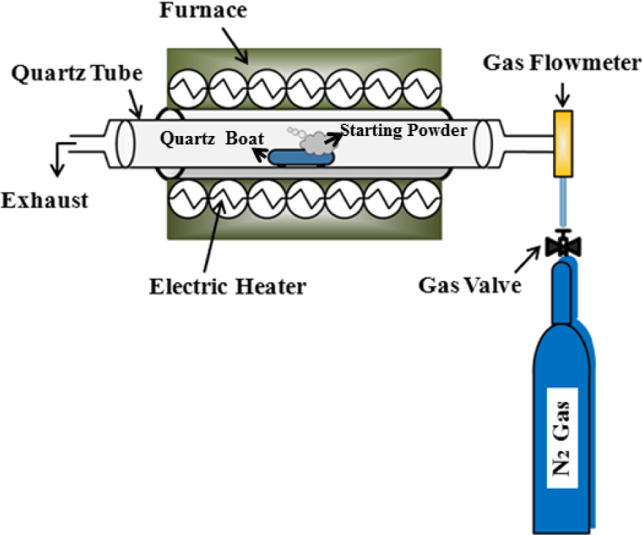
Schematic diagram of the system employed for the synthesis of the ZnO/SnO2 nanocomposite
2.2 Materials Characterization
The morphology of the ZSO compound produced was examined with a Hitachi S4700 field-emission scanning electron microscope (SEM, Hitachi, Tokyo, Japan). The SEM system was equipped with an energy-dispersive X-ray (EDX) spectrometer. To investigate the chemical composition and stoichiometry of the compound, the EDX spectroscopy technique was employed. The crystal structure parameters of the nanostructures were obtained from hard X-ray, low-angle, reflectivity measurements using a Philips PW1710 powder diffractometer (Philips, Amsterdam, Netherlands) with a copper anode source (Cu-K-alpha, lambda=1.54 Å), operating at 0.8 kW with an accuracy of 0.015° 2-theta. The scattered reflected X-rays were detected with a proportional Xe gas-filled detector.
2.3 Fabrication and Characterization of the Dye-sensitized Solar Cell
Fluorine-doped tin oxide conductive glass (FTO) plates were cleaned in an ultrasonic bath with detergent, deionized (DI) water, acetone and ethanol, successively, each step lasting 20 minutes. The FTO substrates were rinsed with DI water between steps. Next, the FTO substrates were immersed in a 40 mM solution of TiCl4 in DI water and heated at 70°C in an oven for 40 minutes, rinsed with DI water and ethanol and dried in air. The ZnO/SnO2 nanocomposite was washed in ethanol and then dispersed in the ethanol using an ultrasonic horn for three minutes (two seconds ON, two seconds OFF). The dispersed suspension was left in a fume hood to become viscous and form a slurry. The slurry was deposited on the FTO glass by the doctor blade method (active area 5×5 millimetres) and the resulting electrodes were sintered gradually from room temperature to 450°C according to the following programme: (180°C (10 minutes), 320°C (10 minutes), 390°C (10 minutes) and 450°C (30 minutes), with a 30 minutes rise time between each step. The electrodes were cooled down to 80°C and immersed in the dye bath overnight. The dye solution was 0.2 mM D35-cpdt organic dye in ethanol. The dyed films were washed with ethanol and dried in a vacuum. Pt electrodes were fabricated by drop-casting a solution of 0.2 mM H2PtCl6 in ethanol on a hole-drilled FTO substrate and the subsequent sintering of the electrodes at 450°C for 30 minutes. Dyed ZnO/SnO2 working electrodes and Pt counter electrodes were sealed together with Surlyn polymeric sealant, and the cobalt liquid electrolyte (consisting of 0.2 M Co(bpy)3(PF6)2, 0.05 M Co(bpy)3(PF6)3, 0.1 M LiClO4 and 0.2 M 4-TbP) was injected between the two electrodes through the counter electrode holes. The counter electrode holes were then sealed with the Syrlyn and glass to prevent the leakage of the electrolyte. Silver paint was used to make the electrical contacts. A DekTak 3 profilometer (VEECO/SLOAN DEKTAK 3, New York, US) was used to measure the thickness of the working electrodes, which was around 14 microns. A sun simulator (Newport, model 91160) along with a Keithley model 2400 source meter was used to measure the efficiency of the solar cells using a black mask in Am 1.5 sunlight conditions. Intensity filters were used to measure the DSSC efficiency in different light intensities. The internal photon-to-current efficiency (IPCE) spectra of the DSSCs was measured using a homemade set-up consisting of a Xenon lamp (Spectral Products, model ASBXE- 175) and a monochromator (Spectral products, model CM110), a calibrating silicon diode (Thorlab, model LM1RM), a Keithley model 2700 multimeter as the data acquisition unit, and a current lock-in amplifier (Stanford research systems, model SR830DSP) to read the current of the solar cell by measuring the voltage of a series-connected 100 Ω resistor.
3. Results and Discussion
The cotton-like product in the source material boat consisted of a large number of microfibres (Figure 2(a)). SEM images of these cotton-like products are shown in Figure 2(b-f). The microfibres formed from this compound are randomly entangled with each other (Figure 2(c,d)).

Photograph of the cotton-like product on the top of the source material surface: (a) SEM images of the tips of the ZSO nanowires, (b) ZSO microfibres entangled with each other, (c) a ZSO product which looks like ‘brushwood’, (d) a branched ZSO nanowire, (e) and a high resolution SEM image of a branched ZSO nanowire (f)
Figure 2(d) shows a low-magnification image of the as-synthesized product, which looks like a ‘brushwood’, with the dimensions 40–50 μm length, 1 μm width, and several hundred nanometres thickness. The image shows ‘brushwood’ surrounded by radially-oriented nanowires with widths of about 100 nm; the nanowire branches have particles at their growing ends with a diameter of more than 100 nm. The presence of particles at the tips of the nanowires is suggestive of a Sn-catalysed VLS growth process, where the particles at the tips of the nanowires are Sn and the nanowires are Sn-doped ZnO [26]. The possible VLS growth of the novel structure presented in this study can be separated into two stages. The first stage is the fast growth of the ZnO axial micro-brushwood, which grows very rapidly; these ZnO brushwood crystals serve as the substrate for the growing ZnO nanowires [27]. The second stage of growth is the nucleation and epitaxial growth of the nanowires due to the appearance of tiny Sn droplets on the ZnO brushwood surface. It is suggested that SnO2 reacts with carbon to form Sn vapour according to the following chemical reaction:

The Sn vapour generated would condense onto the ZnO brushwood substrate to form a catalyst droplet-assisted growth in the VLS process. The Sn particle initiates the growth of the ZnO nanowire, where the nanowire has an epitaxial, orientational relationship with the substrate because of the least lattice mismatch [28]. As expected from the VLS process, the Sn droplet acts as a catalytic surface and is responsible for adsorbing the incoming molecular species. The nanowire continues to grow following the VLS growth process. In VLS growth, it is generally believed that it is the catalyst particle at the tip that determines the size and growth rate of the nanowire, and the surface termination of the substrate may have little effect on growth. Controlling the size of the catalytic particles can effectively control the size of the semiconductor nanowires [13]. Figure 3 schematically shows the process of growth of the ZnO nanowires.

Schematic diagram of the growth process of the ZnO nanowires with Sn particles as a catalyst and a ZnO microfibre as a substrate
urther investigation is needed to elucidate better the exact mechanism of growth of the ZSO nanocomposite described in this work. An EDX image map of the nanowire tips and high resolution transmission electron microscopy (HRTEM) of the structure would contribute to a better understanding of the formation mechanism of the SZO nanostructures. At present, it seems that the above-mentioned VLS mechanism of growth is in agreement with the observed/indicated presence of particles at the tips of the nanowires (see Figure 2(b)), and also with EDX analysis of the nanowire tips (Figure 4(a)).

(a) Energy-dispersive X-ray (EDX) pattern, (b) X-ray diffraction (XRD) pattern of the ZnO/SnO2 nanocomposite. The inset shows the XRD peaks of the Zn2SnO4 from JPCPDF card no. 14-0381. The overlaid black bars are the XRD peaks of the ZnO from JPCPDF card no. 36-1451
The EDX pattern of the nanowire tips revealed the presence of Zn and Sn at the tips. The smaller amount of Sn compared to Zn confirmed that the nanocomposites predominantly contain ZnO and only small amounts of Sn particles at the tips (Figure 4.a). In the XRD pattern of the ZnO/SnO2 nanocomposites shown in Figure 4(b), the ZnO diffraction peaks correspond well with the (100), (002), (101), (102), (110), (103), (200), (112) and (201) planes of the standard pattern of the hexagonal wurtzite phase of ZnO, (space group: P63mc, JPCPDF file no. 36-1451, which is overlaid with black bars in the XRD spectrum of Figure 4(b)) with lattice constants of a = b = 3.25 Å and c = 5.21 Å. The peaks observed at 2θ = 37, 41.6, 55 and 61 in the XRD pattern are indexed to the cubic phase of Zn2SnO4 (space group: Fd-3m, JPCPDF file no. 14-0381, shown in the inset of Figure 4(b)) with a lattice constant of a=b=c=8.6 Å. Our XRD spectra shows all the peaks of the Zn2SnO4 except for the one at 2θ=35 degrees.
Figure 5(a) and Table 1 show the current-voltage characteristics of the fabricated device under different light intensities. The incident photon-to-current efficiency (IPCE) data of the fabricated solar cells is shown in Figure 5(b). The ZnO/SnO2 nanocomposite shows a 0.34% photon-to-current conversion efficiency which is a moderate and rather low efficiency for ZnO nanostructures, bearing in mind that in the present work the solar cells were not optimized for the best efficiency. The branched structure of the large-diameter (>100 nm) nanowires leads to a low surface area of the film, which then causes a low short-circuit current. According to the size of the ZnO/SnO2 nanocomposite, we expected an order of magnitude lower short-circuit current densities compared to the ZnO nanoparticle-based DSSCs [29], and even compared to sub-100 nm diameter ZnO nanowire-based DSSCs [30]. Simple calculation shows that the volume of a 100 nm diameter nanowire, calculated per unit length, is approximately equal to the volume of a 20 nm diameter nanoparticle with a total surface area around 10 times larger than the corresponding area of the nanowire per unit length. While also taking into account the much higher packing density of the nanoparticles in mesoporous films in comparison to the packing of branched nanowires (see also Figure 2), the low-measured current of the ZSO nanowires compared to ZSO nanoparticle-based DSSCs is thus explained. A mixture of our ZSO composite with ZnO nanoparticles could effectively increase the surface area of the film, having the benefits of 1D and light-scattering ZSO composites in the film to increase the PCE of the DSSC. The diffusion length of the electrons inside a ZnO nanowire is rather high, and increasing the thickness of the ZnO nanowire-based DSSCs photoanode (even up to 63 micrometre s for special case) could increase the current [29,31].
Solar cell characteristics of dye-sensitized solar cells with ZSO nanocomposite photoanodes and a cobalt-based electrolyte

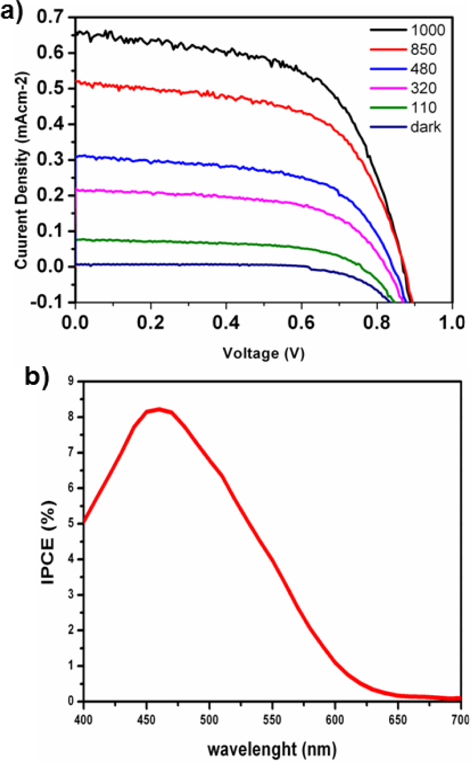
(a) Current-voltage curves of the fabricated DSSC using a ZSO nanocomposite in different light intensities. (b) Incident photon-to-current efficiency (IPCE) of the fabricated DSC
Compared to the results from the vertically-aligned single crystalline ZnO nanowires, the PCE values we obtained are interesting because of the very high open circuit voltage of 870 mV (although they have a poor surface area) in one sun and 760 mV in 10% of one sun intensity without any further pre-treatment (this may be indicative of low trap density and low recombination due to band bending). In DSSCs, the intra band-gap states are filled up by injected electrons, and the Fermi-level position indicates the highest unoccupied trap state in the semiconductor. Regarding the low surface area of our ZSO structure compared to ZSO nanoparticles, such a high VOC can also be indicative of the low trap density and high crystallinity of the ZnO wires. Furthermore, band bending may have taken place in such structures (due to the >100 nm diameter), which keeps the injected electrons in the core of the nanowire, impedes recombination and improves the VOC of the device. It has the potential for use in DSCs, since it has a very promising 1D structure that could be of use due to the fast electron transport inside the working electrode, and could be of interest in combination with the high surface area nanoparticles in a DSC photoanode. Thus, our results confirm the possibility of using the ZnO/SnO2 nanocomposite in liquid-based DSCs, where the large morphology of ZSO structures is convenient for the diffusion of bulky cobalt complexes, thus allowing for the fast diffusion of redox mediators inside the liquid electrolyte. The integrated current from IPCE is 0.59 mA/cm2, which is in good agreement with the short-circuit current density, thus showing that there are no diffusion limitations inside the cell. The IPCE spectra show the spectral absorption of the organic dye, which absorbs from 350 nm to 750 nm. Absorption in red wavelengths is much lower.
4. Conclusion
In summary, we synthesized a novel cotton-like ZSO nanocomposite by the carbothermal evaporation method. Taken together, the results presented show that Sn can act as an efficient catalyst for the high-yield growth of very long, extremely straight and quasi-aligned arrays of single crystalline ZSO nanocomposites. This non-substrate flexible composite with high porosity and good mechanical stability could offer opportunities for further fundamental research, as well as technological applications. Cobalt electrolyte-based DSCs fabricated from these structures show a high open circuit voltage and fill factor. These 1D structures have the benefit of fast electron transport inside the working electrodes and can be interesting in combination with high surface area nanoparticles in DSC photoanodes. Further work should be targeted to the optimization of these DSCs to obtain higher PCEs and to incorporate ZnO nanoparticles in the structure (Figure 6). Controlled experiments to optimize the ratio of ZnO to SnO2 in order to obtain the best performance in DSSCs are needed for the further improvement of the ZSO nanowire device. By such means, the PCE could be increased to reach values promising for photovoltaic and other technological applications.

Mixture of the ZSO composite with ZnO nanoparticles
Footnotes
5. Acknowledgments
The authors, R.I and A.I, wish to acknowledge the ARRS grants J1-4109, J1-4136, J3-4108 and P2-0232, which enabled them to carry out this research.