
Abstract
The tethered space robot system (TSR), which is composed of a platform, a gripper and a space tether, has great potential in future space missions. Given the relative motion among the platform, tether, gripper and the target, an integrated approach model is derived. Then, a novel coordinated approach control scheme is presented, in which the tether tension, thrusters and the reaction wheel are all utilized. It contains the open-loop trajectory optimization, the feedback trajectory control and attitude control. The numerical simulation results show that the rendezvous between TSR and the target can be realized by the proposed coordinated control scheme, and the propellant consumption is efficiently reduced. Moreover, the control scheme performs well in the presence of the initial state's perturbations, actuator characteristics and sensor errors.
1. Introduction
On-orbit capture technologies have recently attracted much attention for their potential application in future space missions, such as on-orbit maintenance, on-orbit assembly, on-orbit re-fuelling and debris mitigation.[1–4] Based on the characteristics of different targets, these technologies are classified as cooperative capture or non-cooperative capture. The dynamical and configuration parameters of the targets are often known or available in the case of cooperative capture, but are unknown or unavailable in the case of the non-cooperative capture. In recent decades, the cooperative capture concept has been successfully demonstrated by manipulator arms, such as ETS-VII, Canadarm and the Orbital Express.[5] With a non-cooperative target, such as a malfunctioning satellite, the capture is extremely risky, difficult and dangerous. Using several hectometres of tether, the tethered space robot system (TSR) has great potential for non-cooperative capture.
The approach control of this flexible multi-body system is a very challenging research issue, which involves two research areas. One is the non-cooperative target detection and tracking, and the other is the rendezvous control using the space tether. In the area of non-cooperative target detection and tracking, Du et al. studied the pose measurement problem presented by a large non-cooperative satellite based on two collaborative cameras.[6] Nikolaos presented a nonlinear and recursive identification mechanism in a motion-based detection and tracking algorithm.[7] Thienel et al. devised a nonlinear approach for estimating the body rates of a non-cooperative target vehicle and coupling the estimation to a tracking control scheme.[8] Working from the assumption that the non-cooperative target has been detected and measured by the visual perception system of TSR, this paper focuses on the rendezvous control using the space tether. In this area, Carroll first discussed the tether-mediated orbital rendezvous between the tether tip and the space shuttle.[9] Several years later, Carroll provided a preliminary design for a tether transport facility capable of providing between 0.6 and 1.2 km/s velocity increments to payloads.[10] Stuart originally considered the in-plane cooperative tether-mediated rendezvous between a free-flying spacecraft and the tether tip by combining tether reeling with thrusters on the tether tip.[11] More recently, Blanksby and Trivailo devised a method for achieving a gentle rendezvous by the tension controller.[12] Westerhoff discussed a linear control strategy to minimize errors in rendezvous for a spinning momentum-exchange system, which assumed that the tether is reasonably close to the desired rendezvous position.[13] Williams studied payload capture problems and examined the influence of thermomechanical and tether flexibility effects.[14–17] However, most of the previous studies have focused on the dynamic and control problem of a long-tether system which is known as the tethered space satellite system (TSS).[18–20] Rather than TSS, this paper proposes a TSR for the on-orbit capture task. The space tether of TSR is only a few hundred metres long, which is much shorter than the traditional TSS. The tether deployment depends on ejection velocity instead of the gravity gradient, and the whole capture operation only takes a matter of minutes. The short dimensions and different deployment procedure distinguish TSR from the traditional TSS. Furthermore, the relative states of the target are much more important in the studies of TSR. Thus, previous achievements are not adopted for TSR. In studies of TSR, Mankala and Agrawal examined dynamic modelling and simulation.[2] Nakamura discussed the collaborative control method,[21] but did not consider the attitude disturbances and relative motions among the platform, tether, robot and target. The multi-body relative motion should not be ignored because of its importance to the direction of tension and the approach instruction. With consideration for the relative motions and attitude disturbances, the approach control problem of TSR is studied in this paper.
The paper is organized as follows. In section 2, a brief description of TSR is presented. In section 3, the approach model of TSR is derived, including the attitude model and the multi-body relative motion among the platform, tether, gripper and target. In section 4, an integrated coordinated approach control scheme using the tether tension, thrusters and reaction wheel is designed. The numerical simulations are shown in section 5 and finally conclusions are made.
2. Description of TSR
TSR is composed of a platform, a tether and a gripper (Figure 1). The gripper and the platform are connected by the tether. The advantages of TSR for on-orbit capture are summarized as follows:
The capture distance of TSR is several hundred metres, which improves the security of the platform during the on-orbit capture task.
The closing manoeuvre is unnecessary for the long capture distance, which greatly reduces the propellant consumption.
If the gripper has problems during the on-orbit capture task, it will not be lost because of the tether.

Configuration of TSR
The mission sequence is described in Figure 2. First, the gripper is fixed to the platform. TSR approaches the target at several hundred metres and then releases the gripper at a certain initial velocity. Using the initial velocity, the gripper consequently flies toward the target and docks at an appointed position under the control of the thrust and tether tension. After the docking, the gripper captures the target and performs a number of tasks, such as retrieving the target or assisting it in orbital transfer. In the approach, the tether is tightened and deployed in a passive mode. The tether tension is larger than zero. The schematic diagram of the tether control device is shown in Figure 3. How to keep the tension is not the focal point in this paper. It is assumed that the tension can trace the instruction by the tether control device.

Mission sequence of TSR

Schematic diagram of the tether control device
3. The Approach Model of TSR
The dynamic modelling of this flexible multi-body system is a challenge. The existing literature suggests three models of varying complexity.[22,23] The simplest model is the dumbbell model, which assumes the system involves two end-bodies joined by a rigid rod.[14,20,24] It ignores the elasticity and flexibility of the tether. The more complex model is the spring-mass model, which assumes a system of two end-bodies joined by a spring.[16,25] The spring goes slack when the end-bodies are closer than the natural length of the tether. The tether flexibility is still ignored in this model. The most complex model is the multi-elements model. In this model, the tether is represented by a sequence of elements, such as finite elements or beads connected by massless springs. The former is the finite element model and the latter is the most popular bead model.[17–19,26,27] In this model, the tether mass elasticity and flexibility are all considered. The tether is more realistically represented by increasing the element number. In this paper, the bead model is used for the dynamic modelling of TSR. It assumes the tether to be a series of point masses connected by i massless springs (Figure 4). There are n+1 tether frames (TFi,i = 1 … n + 1) in the bead model. The origin of TFi is at bi. The three axes are defined by unit vectors (

Bead model of TSR
In addition, the target orbital frame (TOF), the platform orbital frame (POF) and the body-fixed frame (BF) are used in the approach modelling of TSR (Figure 5). TOF (
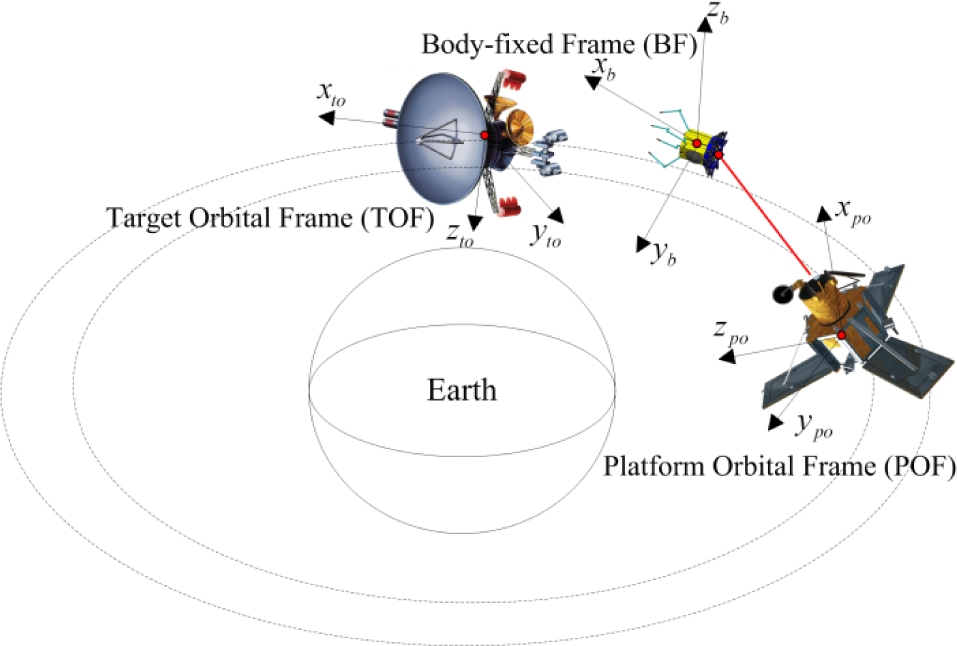
Reference frames
In the approach, the tether tension, thrusters and the reaction wheel are all utilized to save the propellant consumption. Actuators in the gripper are configured as in Figure 6. The attitude is stabilized by thrusters and the reaction wheel. In the control channels around directions
Assignment of actuators


Configuration of the gripper actuators
3.1 The Attitude Model of TSR
In the approach, the reaction wheel and thrusters are used to stabilize the attitude of the gripper. The attitude control model is:

where

ω = [ω
x
ω
y
ω
z
]T is the gripper angular velocity vector;
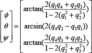
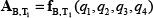
For the convenience of expression and measurement, the output attitude is expressed in the form of Tait-Bryan angles instead of quaternions in this paper. The derivation of the Tait-Bryan angles (roll, pitch and yaw error [φ,θ,Ψ] T ) is:
3.2 Trajectory Model of TSR
The relative motion between TSR and the target is the core in trajectory modelling. It is assumed that the target satellite flies along an unperturbed circular orbit. The Hill equation is used in this section.
In the trajectory modelling, the unit vector of TOF is (
The tether coordinate system TFi is represented as:

The rotation matrix from TFi to TOF then yields:

The rotation matrix from BF to TF1 is represented as:
Then, the acceleration of gripper, platform and bead bi is derived in TOF:

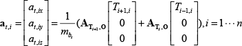
where ms, mp and mbi are the respective masses of the gripper, platform and bead bi; Fsx, Fsy, Fsz are the thrusts of gripper along the x-, y- and z-axes of BF, respectively; Ti,i+1 = –Ti+1,i (i = 0 … n) is the tether tension along the i th link (“tether i”); and Fpx, Fpy, Fpz are the control thrusts of platform at TOF.
The tether tension is derived by the linear Kelvin-Voigt law.

where li is the natural length of tether i; E is Young's modulus; and A is the area of cross section. EA represents the tether's longitudinal stiffness.
In contrast to the i th elastic link (i = 1 … n), the (n + 1) th link of the tether is assumed to be inelastic. The tether is deployed by varying the length of the (n + 1) th link. When the length of the (n + 1) th link is larger than a designed constant, a new bead appears and a new anchor point is defined. Tn,n+1 is the deployment force of the platform, which is presented by Ttp.
The trajectory model in the approach is derived by the Hill equation in TOF. Where the distance between TSR and the target is much smaller than the orbital radius of the target, the higher-order nonlinear terms of the Hill equation are neglected.

where ω is the orbit angular velocity of the target.
4. Control strategy of TSR
The approach control problem for TSR is a two-point boundary value problem. The system states at the beginning and end of the approach are known. The problem, therefore, is how to control TSR between the initial state and the terminal state, and obtain satisfactory performance. It is a typical optimal control problem. In this research area, Gao et al. studied an optimal control approach to spacecraft rendezvous on elliptical orbit by LQR.[28] Wang et al. introduced an adaptive dynamic programming algorithm for the optimal control of the non-affine nonlinear discrete-time systems.[29] Keith Dupree used the implicit learning capabilities to learn the dynamics asymptotically and studied the optimal control of uncertain nonlinear Euler–Lagrange systems.[30] Wu et al. presented a min–max optimal control of linear systems with uncertainty and terminal state constraints, which is solved through solving a sequence of semi-definite programming problems.[31] However, the approach model is a complex nonlinear system and the terminal states of the platform are especially uncertain. These previous achievements, however, are not suitable for application to the approach control of TSR. An approach control scheme is presented in Figure 7. It contains the open-loop trajectory control and the feedback control. The control strategies for the attitude and trajectory motion are derived, respectively.

Approach Control Scheme of TSR
4.1 Open-Loop Trajectory Optimization
Where the attitude of the gripper is assumed to be firmly stabilized, the influence of the attitude motion is ignored. However, the trajectory model is still too complex for the controller design. In the approach, the tether is short and deployed in a passive mode; the gripper flies to the target by the initial release velocity. The tether's tension is very low in order to reduce the interference to the gripper. Therefore, the influence of tether mass, elasticity and flexibility is weak. The bead model is simplified to a dumbbell model in this section.

where
Moreover, the platform does not manoeuvre in the approach. The approach trajectory model is thus represented in the following state-space form:

where
The objective of this section is to find a physically realizable trajectory that guides the gripper from a given initial state to a fixed terminal state. The problem is well defined mathematically as a two-point boundary value problem. In general, there are a finite number of trajectories that satisfy the boundary conditions. Therefore, the numerical solution is not necessarily unique. Despite the numerous possible measures for defining an optimal trajectory, the trajectory which satisfies the boundary conditions and minimizes the integral square of the thrust is defined as optimal in this paper, which may reflect the advantage of coordinated control with tension and thrust.
The optimal control problem considered in this section is stated as follows: Find the state–control pair {

This is subject to the nonlinear state equations given by equation (11), the initial and final boundary conditions


and the box constraints

where
The solution to such an optimal control problem is generally difficult to obtain using standard approaches. The first approach is to view the problem in dual space by the application of Pontryagin's maximum principle. Unless the problem is simple and has an analytic solution, then discretization is inevitable in obtaining an approximate solution.[32] The more effective method for solving the problem is the use of direct methods. Direct methods transform the continuous-time problem to a discrete parameter optimization problem by using a discretization method to approximate the state equations and cost functions. Most discretization methods use sequential quadratic programming algorithms to solve the underlying nonlinear programming problem, such as the Hermite–Simpson method, the fifth-order Hermite–Legendre–Gauss–Lobatto method and pseudo-spectral methods. These methods are extremely efficient for solving even the most complex of problems. The pseudo-spectral method parameterizes the state and control variables by orthogonal polynomials (e.g., Legendre and Chebyschev). This method approximates dynamics at various quadrature points, such as Legendre–Gauss, Legendre–Gauss–Radau and Legendre–Gauss–Lobatto points.[33–36] In this paper, the Legendre–Gauss–Radau pseudo-spectral method is used to solve the open-loop trajectory optimization. The detailed optimization process can be found in reference [36].
4.2 Feedback Trajectory Control
Under the optimal continuous control inputs, the gripper approaches the target along the open-loop trajectory. However, the model errs between equation (9) and equation (10) with the consequence that the gripper does not approach the target. In addition, the optimal open-loop trajectory is sensitive to errors in the initial state, actuator errors and external disturbances. Therefore, the open-loop trajectory is implemented with a feedback controller to achieve efficient closed-loop performance.
A proven technique for providing feedback control around the time-varying reference trajectory is receding horizon control, which linearizes the dynamic model and solves a linear optimal control problem over a future finite horizon with the initial state equal to the current state.[37–39] Another proven technique is to track the open-loop trajectory by formulating the discretized problem as a quadratic programming problem, for which analytical solutions are available.[16] Less memory is required to obtain solutions and availability of closed-form solutions in this method. A new and more efficient adaptive control method is used in this paper. First, the nonlinear trajectory model is transformed to a linear and time-varying model by linearizing it along the open-loop reference trajectory. For this time-varying model, besides the receding horizon control and the quadratic programming, Kurina and Marz present a linear-quadratic optimal controller for the time-varying descriptor system.[41] Qi et al. studied the optimal ensemble control of stochastic time-varying linear systems by the minimum norm solution of a Fredholm integral equation.[42] In this paper, the linear time-varying trajectory model is changed to a linear time-invariant system by separating small time-varying elements and designing virtual control inputs. The linear quadratic regulator is used and the actual control inputs are finally derived by the adaptive control theory. In contrast with previous methods, this method is much simpler and needs less memory and calculation. However, it should be noted that this method can only be applied to a state matrix with small time-varying elements.
The linear time-varying model around the reference trajectory is:
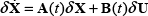
where δ

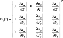
where
Where the mass of the platform is much larger than the mass of the gripper, the influence of Ttp on the platform is much smaller. In contrast to the open-loop tension Ttpr, the influence of δT on the platform is much smaller. The perturbed state variables of the platform are neglected in the feedback control. Only the system states of the gripper are considered to simplify the problem in this section. Therefore, the state dimension of the model (equation 16) is reduced from 12 to 6. The simplified model is

where δ
The quadratic performance index is represented as:

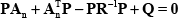
The virtual control law using linear quadratic regulator theory is

where
The actual feedback control law is then derived as

where
4.3 Feedback Attitude Control
The attitude control of the gripper is similar to the traditional satellite attitude control.[43,44] The primary attitude interference is the tether's tension moment. The actuators are thrusters and a reaction wheel. The attitude model is represented as:

where
The quadratic performance index is represented as:

The attitude control law using linear quadratic regulator theory is

where

Moreover, control dead zones in pitch and yaw channels are designed for handling the small attitude errors to save propellant.
5. Numerical Results
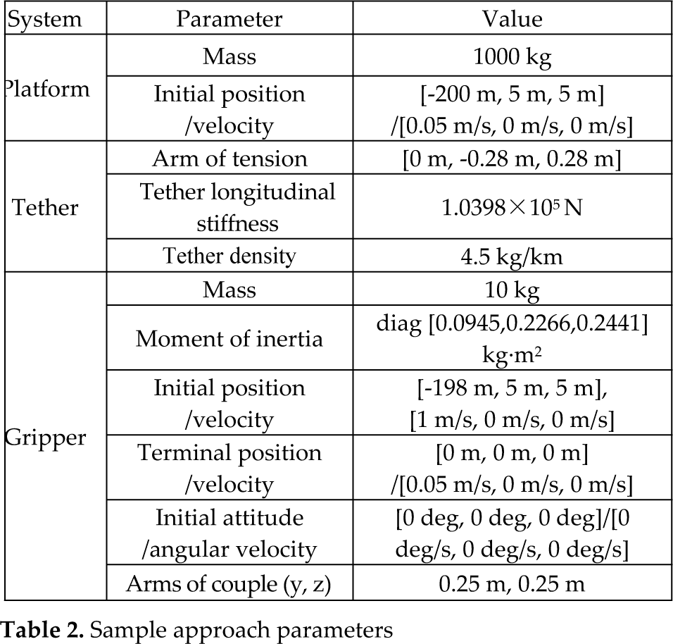
A representative approach is selected to demonstrate the performance of the proposed approach control scheme. The target is assumed to be in an orbit with a radius of 6,871 km, and the orbit angular velocity is 0.0011 rad/s. The key parameters are given in Table 2.
Sample approach parameters
To prevent the tether from slackening, the tension must be larger than zero. Then, the box constraints of the control inputs are
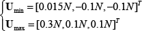
With the initial estimate of zero control inputs, the Legendre-Gauss-Radau pseudo-spectral method is used for open-loop trajectory optimization. The optimal control inputs become continuous via Lagrange interpolation. Then, the scheme is validated by the bead model of TSR (equation 9). The corresponding optimal continuous control force is shown in Figure 8. Figure 8.a shows the comparison between the tether tension Ttp and T1,0. Ttp is the deployment tension at the tether control device of the platform. With the bead model of TSR, T1,0 is the actual tension at the gripper. The maximum and minimum deployment forces (Ttp) are 300 mN and 15 mN. The actual tension T1,0 can track Ttp. The maximum tracking error is less than 5 mN. Figure 8.b shows the thrusts of the gripper. The thrusts are less than 16 mN. For the deviation out of the orbital plane, Fz is much larger, which consumes more propellant. Under the optimal continuous control inputs, the gripper approaches the target along the open-loop optimal trajectory.

Optimal open-loop control inputs
Even though the numerical method is used to generate the optimal control profile, it is desirable to implement the solution with an appropriate feedback strategy such that closed-loop stability can be demonstrated. Therefore, the open-loop optimal control inputs are stored, or even determined just before initiating the control actions. Then, a feedback controller is used to implement the required controls. When the influence of attitude is not considered in the open-loop optimal control, the controller is validated in the integrated model, which contains the dynamic coupling between the trajectory model and the attitude model (equations 1 and 9).
The weighting matrices are selected as

States of the gripper in a representative approach
Control inputs in a representative approach
Furthermore, the performance of the coordinated approach control scheme is validated by the initial state errors, actuator errors and external disturbances. When the tension is positive so as to prevent the tether from slackening, it is difficult to track the open-loop trajectory for the initial deviation of position and velocity at the –x direction. Two methods are used to solve this problem: (A) several thrusters are fitted in the gripper to provide the thrust at the +x direction, and (B): an appropriate initial state is selected to decrease the influence of initial state perturbation. For example, if xs0 is distributed randomly within the range [x*s0 − Δx*s0,x*s0 + Δx*s0], the initial state is selected as xs0 = x*s0 − Δx*s0, and the disturbance range is selected as [0,2Δx*s0]. Method (B) is used in this paper. The perturbations of initial conditions are distributed randomly within the following ranges:


The characteristics of actual thrusters, the tether control device and the sensor errors are all considered in the simulation. For example, the small tether tension is difficult to track. Thus, the maximum deviation of the steady-state may reach ±30%. The key parameters are given in Table 3.
Key parameters of actuators and sensors

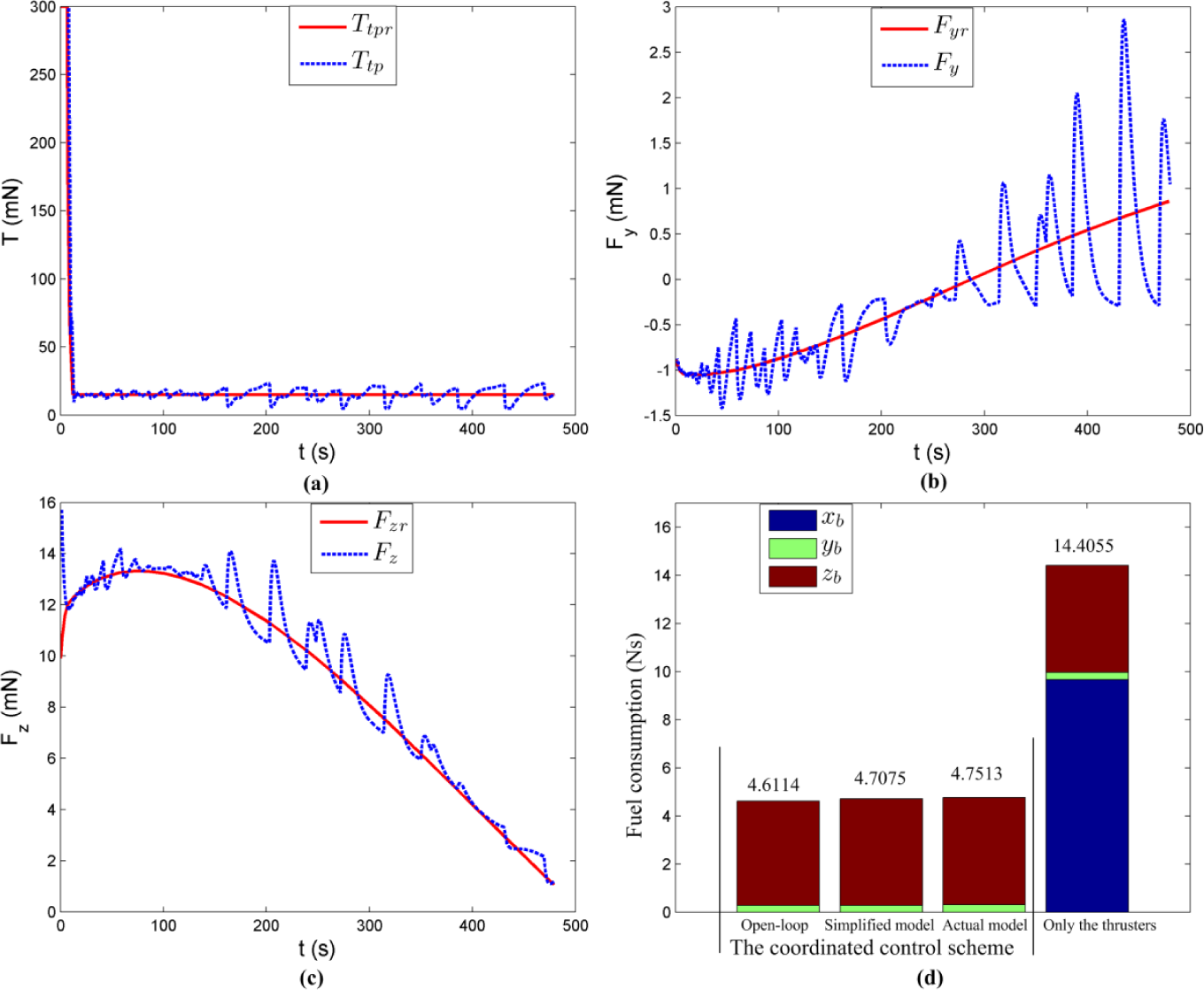
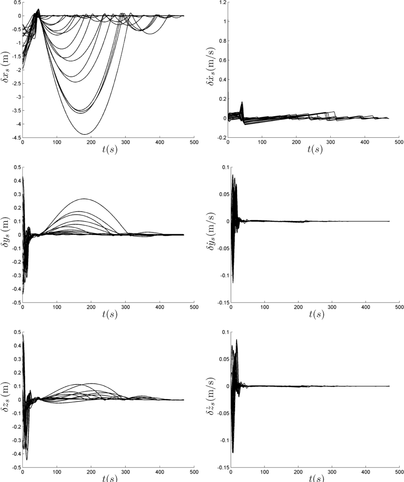
A total of 20 simulations are performed using the coordinated approach control scheme with the initial perturbations, actual actuator characteristics and the sensor errors. Numerical results are shown in Figures 11 and 12. Under the coordinated approach control scheme, all system states converge to their desired values by the capture time. Figure 11 shows the dispersions of the system states δ
Dispersions to δ
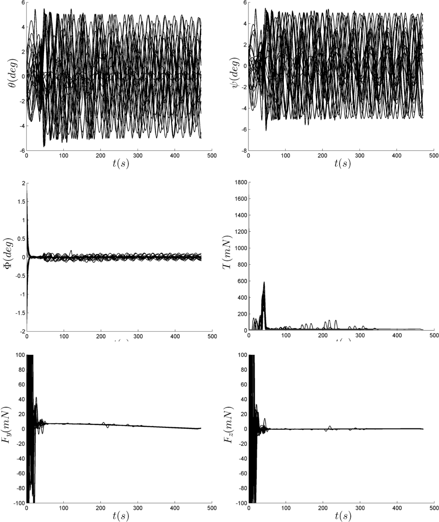
Dispersions to the gripper attitude and the control inputs
The closed-loop simulations show that the coordinated approach control scheme is effective in the presence of initial states perturbations, actuator characteristics and sensor errors. However, several questions still remain, including those of how to select the suitable sensors to observe all of the system states, how to achieve the required tether tension, and whether the system still performs as well in the presence of additional uncertainties. Nevertheless, the results presented are extremely promising given that the control scheme of TSR is capable of achieving rendezvous in the on-orbit capture task.
6. Conclusions
An approach model of TSR is presented, which includes the attitude model and the relative trajectory model between TSR and the target. An effective coordinated approach control scheme using the tether tension, thrusters and a reaction wheel is developed. It contains open-loop trajectory optimization, feedback trajectory control and attitude control. In the control scheme, the open-loop trajectory is first optimized by the pseudo-spectral method. Then, the approach model is linearized along the open-loop trajectory to transform a highly nonlinear model into a linear time-varying model. Finally, a feedback controller is designed by adaptive control theory and a linear quadratic regulator. A representative on-orbit capture scenario in low Earth orbit is selected to demonstrate the performance of the proposed scheme. The gripper can approach the target under the coordinated control scheme. At the terminal, the maximum errors of positions are less than 0.1 m; the maximum errors of velocities are less than 0.01 m/s; the maximum attitude angle errors of 0, θ, Ψ and φ are 4 deg, 4 deg and 0.1 deg, respectively. The propellant consumption is 4.7513 Ns, while that of the thruster control is 14.4055 Ns. It clearly demonstrates that the coordinated control scheme can efficiently reduce the propellant consumption. Moreover, the coordinated approach control scheme performs well in the presence of initial states perturbations, actuator characteristics and sensor errors.
Footnotes
7. Acknowledgments
This work is supported by the National Natural Science Foundation of China (Grants No. 61005062 and 11272256), the Fundamental Research Funds for the Central Universities (Grant No. 3102014JCQ01005) and the Open Research Foundation of Science and Technology on Aerospace Flight Dynamics Laboratory (Grant No. 2012afdl022).