
Abstract
The tethered space robot (TSR) is a new concept of space robot which consists of a robot platform, space tether and operation robot. This paper presents a multi-objective optimal trajectory planning and a coordinated tracking control scheme for TSR based on velocity impulse in the approaching phase. Both total velocity impulse and flight time are included in this optimization. The non-dominated sorting genetic algorithm is employed to obtain the optimal trajectory Pareto solution using the TSR dynamic model and optimal trajectory planning model. The coordinated tracking control scheme utilizes optimal velocity impulse. Furthermore, the PID controller is designed in order to compensate for the distance measurement errors. The PID control force is optimized and distributed to thrusters and the space tether using a simulated annealing algorithm. The attitude interferential torque of the space tether is compensated a using time-delay algorithm through reaction wheels. The simulation results show that the multi-objective optimal trajectory planning method can reveal the relationships among flight time, fuel consumption, planar view angle and velocity impulse number. This method can provide a series of optimal trajectory according to a number of special tasks. The coordinated control scheme can significantly save thruster fuel for tracking the optimal trajectory, restrain the attitude interferential torque produced by space tether and maintain the relative attitude stability of the operation robot.
Keywords
List of symbols
mP/kg the mass of robot platform
mR/kg the mass of operation robot
G/m3/(kg · s2) universal gravitational constant
Me/kg the mass of the earth
Ft tension force of space tether
Re/km orbital radius
l/m total releasing length of space tether
lR/m tether length from R to O1
lP/m tether length from P to O1
Ω/rad/s orbital angular velocity
o
1
θ and φ/rad in-plane and out-of-plane angle of operation robot, respectively
ax, ay and az/m/s2 thrust acceleration of operation robot
t0 and tf/s initial time and terminal time
Φ v velocity transfer matrix
Φ w position transfer matrix
M times of velocity impulse
δ/s time impulse
Δ
ϑ arbitrary row vector suited to corresponding dimensions
ω c /rad/s angular velocity of operation robot
ω r /rad/s relative angular velocity of operation robot
ω t /rad/s target angular velocity
Ω/rad/s angular velocity vector of reaction wheels
Θ/rad maximum view angle
θ/rad real-time view angle measurement
Fxs, Fys and Fzs/N distribution control force of thrusters
Jf cost function of optimization and distribution control force
w1 and w2 weight coefficient
T0/°C initial temperature
Tmin/°C minimum temperature
n iteration number
ξ annealing coefficient
Ŷ/N · m estimation of attitude control compensation
ω rd /rad/s desired relative angular velocity
t1 and t2/s time constant
T/s control period
lx, ly and lz/m distance between connection point and centroid of operation robot
1. Introduction
With the development of space technology, the number of satellites increases dramatically. As many satellites are used together for a space mission, there have been some technical challenges. Some problems with satellites may emerge. Therefore, many researchers have studied problems of recycling and repair. The tethered space robot (TSR) is a new concept on-orbit mechanism for capturing the uncontrolled satellite, with potential applications for on-orbit maintenance, capture and assembly. This TSR consists of a robot platform, space tether and operation robot. The operation robot is released from the robot platform, attached by space tether; it then approaches the target automatically, finally capturing the uncontrolled satellite to accomplish on-orbit tasks. The TSR has a larger operation radius and better flexibility than a traditional space robot, because the combination of operation robot and space tether can be treated as an extended space arm.
Before the final task, the operation robot needs to arrive at the appropriate position with at a stable relative attitude. Therefore, the key technologies of this problem relate to optimal trajectory planning, tracking control and stability control of the relative attitude.
Generally, researchers have only considered fuel consumption in optimal trajectory planning. However, the approach time is also an important factor in the real task. Therefore, optimal trajectory planning of tethered space robot needs to be further studied. In the traditional process of rendezvous, optimal trajectory planning is based on velocity impulse instead of continuous control force, because of the fuel limitations and thruster identity. The TSR has similar characteristics; however, when the approach distance is relatively short, the tension force of the space tether and the view angle should also be considered. Therefore, optimal trajectory planning of TSR has its own special aspects.
The optimized criteria include single objectives and multi-objectives for traditional optimal trajectory planning based on velocity impulse. Researchers often use genetic algorithms [4], ant colony algorithms [5] and simulated annealing. Luo et al. synthesized many optimized methods for designing an optimal long-distance trajectory based on velocity impulse, and considered the constraints of velocity [6]. Young and David optimized the rendezvous trajectory for two velocity impulses using a genetic algorithm whose variables are amplitude, imposed position and direction of velocity impulse. The optimal criterion is fuel consumption [7]. Zhang et al. proposed multi-objective (time and fuel consumption) optimal orbit transfer strategy using a genetic algorithm and Lambert's theory [8]. The existing studies, however, are dedicated to long- distance rendezvous trajectory, and thus are different from the optimal trajectory planning of a tethered space robot. This paper presents optimal trajectory planning for approaching the target based on velocity impulse, and includes consideration for the final approach and capture task.
The fuel consumption is a major consideration for tracking the optimal trajectory of TSR. To save the fuel of the operation robot, this paper presents a coordinated orbit and attitude control method for tracking the optimal trajectory. For coordinated control, Nakamura et al. discussed the collaborative control of tension force (controlled by the service satellite) and thruster force (controlled by tethered robot) for approaching the target of the tethered retriever, but did not consider attitude [9]. Nohmi designed a tethered space robot, connected to a mother spacecraft through space tether. The attitude of the tethered subsystem can be controlled by tether tension force through its own link motion, and the tethered subsystem rotates when its mass centre deviates from equilibrium, which is controlled by the arm [10]. He also developed a space robot attached to a spacecraft by tether. The spacecraft-mounted manipulator generated the necessary initial momentum for the space robot and adjusted its trajectory by controlling tether tension [11]. Mori proposed the concept of tethered satellite cluster systems whose parts were connected by tethers. He established a coordinated control method using tension force and thrust force, which decreased thruster fuel and improved control precision [12]. A coordinated fault-tolerant nonlinear control method was presented by Godard [13] to control the attitude of a satellite using movement of tether attachment points; his method examined cases where tether deployment suddenly stops and tether breakage occurs. Chang et al. proposed an adaptive coordinated control strategy for a robot system which can control its own movement [14]. The TSR is similar in concept to the above researches, which mention the coordinated control method; however, they only considered one aspect, such as orbit movement or attitude change.
The attitude control problem is a complex topic due to the nonlinear nature of the model, coupled with uncertainties both in parameters and disturbances [15, 16]. Many attitude control methods are available, including linear and nonlinear H∞ [17, 18], adaptive control [19] and fuzzy controls [20, 21]. The reaction wheel has become increasingly popular as an actuator in spacecraft attitude control [22]. Kristiansen discussed the advantages of this type [22]. The reaction wheel is a device that applies torque to spacecraft by control command. Ismail presented several configurations of reaction wheels and the standard reaction wheel control, and angular momentum unloading schemes were adopted for all configurations of the reaction wheel [23]. Jin proposed a simple and effective fault tolerant control method for satellites with four wheels. This method was based on dynamic inversion and time-delay control theory [24].
This paper presents an optimal trajectory of an operation robot for approaching the target based on the multi-objective velocity impulse method. To economize the thrust fuel of operation robot, we present a coordinated orbit control and attitude stability method for tracking the optimal approach trajectory. The rest of the paper is organized as follows: first, a brief description of the tethered space robot is given. Next, the TSR dynamic model is presented in Section II. Then, the optimal trajectory model of the operation robot is introduced for approaching the target based on velocity impulse in Section III. Furthermore, the coordinated orbit control and attitude stability method are detailed for tracking the optimal trajectory in Section IV. Finally, the numerical results of the optimal trajectory and the coordinated control method are plotted in Section V, and conclusions are given at the end.
2. TSR Task Description
This paper proposes a TSR system composed of a robot platform, space tether and operation robot, whose task is on-orbit service. An operation robot is the machine to perform this work. The task flow is described as follows. The operation robot is installed at the robot platform in the initial state. The TSR approaches the position close to 100 metres' distance and level with the target under the guidance, navigation and control of its own equipment.
Then, the operation robot approaches the target after being released from the robot platform, maintaining its relative attitude according to the target attitude. Finally, the operation robot supplies on-orbit service using its own manipulator after reaching the appointed position (<1 m to the target). The TSR is shown in Figure 1.

Tethered space robot construction
This paper firstly studies optimal trajectory planning in approaching the target of the operation robot, which is released by the robot platform by space tether. Then, it provides a coordinated orbit control and attitude stability method for tracking optimal trajectory. The actuators of the operational robot are thrusters and reaction wheels. The thrusters consume the fuel of the operation robot, while the reaction wheels consume electricity from the robot platform through space tether. To save the fuel of the operation robot, this article studies coordinated orbit control using space tether and thrusters, maintaining the relative attitude using reaction wheels.
3. Operation Robot Dynamic Model for Approaching the Target
3.1 Operation Robot Orbital Dynamic Model
First, the dynamic model of TSR is established. The mass of space tether is ignored; the robot platform and operation robot are modelled as two mass points when we establish the orbital dynamic model of the operation robot, which are represented as symbol R and P in circular orbit. The o1 is the centroid of TSR, the o1x1y1z1 frame is the TSR orbit coordinate frame and the o1x2y2z2 frame is the coordinate frame of space tether. The in-plane and out-of-plane angles are θ and φ, respectively. All of these are shown in Figure 2.
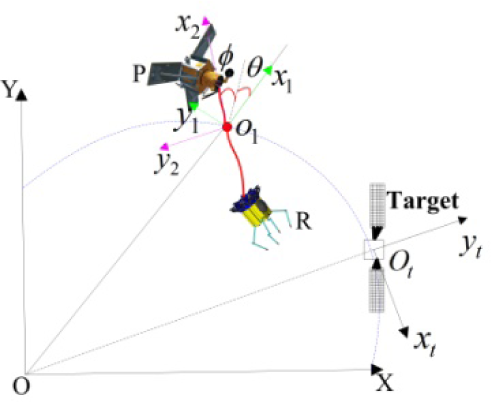
Relevant coordinate frame of TSR
The following dynamic equation of TSR is obtained by Newton's Second Law:

where
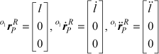
It is assumed that Re is the orbital radius, l is the total releasing length of space tether, lR is tether length from R to O1, and lP is the tether length from P to O1. Therefore, the position vectors


where


Substituting all the terms on the right hand side of Eq. (1) with the equations above and simplifying yields:

where
The relative angular velocity ω O o1 and angular acceleration α O o1 between the inertial frame OXYZ and o1x2y2z2 frame can be expressed in the frame o1x2y2z2:

The
o
1
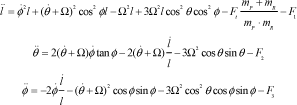
Therefore, the inertial acceleration r̈PR can be expressed as:

Substituting all the terms on the right hand side of Eq. (9) with the Eqs. (7) and (8), and simplifying, we obtain:

The Eqs. (6) and (10) can be set equal to each other to obtain dynamic model of TSR:
Generally, the mass of the robot platform is larger than that of the operation robot; furthermore, the mass of the space tether is ignored. Therefore, the centroid of TSR can be almost considered as the centroid of the robot platform. In this paper, we assume that the target is located in the same circular orbit as the TSR and the releasing length of the space tether is 100 metres level. The relative motion of the operation robot can be described by a Hill equation in the target orbit coordinate frame otxtytzt, as shown in Figure 1.

where ax, ay and az are the thrust acceleration of the operation robot. Denoting the state vector

where
From Eq. (13), the state transition matrix is obtained:
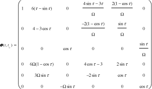
where τ = Ω(t − t0). From Eq. (13), we get its special solution satisfying
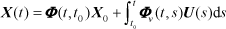
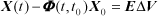
where Φ v is velocity transfer matrix. Eq. (14) can be rewritten as:

Eq. (16) can be rewritten as:

where
It is assumed that

where ti is the time in which the velocity impulse is imposed, Δυ; i = (Δυ xi Δυ yi Δυ zi )T. Substituting Eq. (18) into Eq. (15), Eq. (19) can be obtained:

Eq. (19) can be rewritten as:
where
When two velocity impulses are imposed on the operation robot, it can be calculated by Eq. (20):
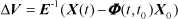
When three (> three) velocity impulses are imposed, the general solution of M velocity impulses can be obtained by Eq. (20):

where ϑ is an arbitrary row vector suited to the corresponding dimensions. If the minimum-norm solution is chosen, Eq. (22) can be rewritten as:

3.2 Attitude Kinematic and Dynamic Model of the Operation Robot
This paper focuses on the coordinated relative attitude control and stability of the operation robot for approaching the target, so it is defined that ω
c
= [ω
cx
ω
cy
ω
cz
]T is the angular velocity vector of the operational robot. The relative attitude kinematic equation of the operation robot is established using attitude quaternion in this paper. The paper also defines
Thus, the relative attitude quaternion kinematic equation is obtained by:

where ω r is rotation angular velocity of operation robot relative to the target. The operation robot is provided with four reaction wheels, where three are installed by three inertia axes and the fourth is installed in the position at the same angle as the other three.
From the relative attitude relationship, it is concluded that:

where ω
t
is target angular velocity,

Assume:

where:


Let
Thus, the attitude dynamic equation can also be rewritten as:

4. Multi-objective Trajectory Optimization Model Based on Velocity Impulse
The task of TSR is capturing and repairing the uncontrolled satellite. The operation robot should firstly arrive at the desired position. Therefore, the approach time is important. However, thruster fuel is limited. Therefore, this paper presents a multi-objective optimization model based on velocity impulse, which considers the thruster fuel and the approach time simultaneously.
4.1 The Target Function of the Trajectory Optimization Model
The thruster fuel consumption of the operation robot is selected as the first target function, and the approach time is the second function. To simplify the calculation, the minimum-norm solution (solution of Eq. (23)) of total velocity impulse is considered as the total fuel consumption.
The optimal target function is:
The constraint condition is:


4.2 Trajectory Optimization Variable and Trajectory Constraint Conditions
It is easy to obtain optimization variables Δυ; i (i = 1,2…M) and tf from the Eqs. (33) and (34). However, the terminal equation constraint is hard to handle because of the selection of the optimization variable Δυ i (i = 1,2…M). Therefore, σ i (i = 1,2…M) are selected as optimization variables instead of Δυ i . The Δυ i can be obtained from Eq. (21) or Eq. (23). The terminal equation constraint is satisfied automatically:

where ti is the time of imposing velocity and σ
i
is the unitary result of ti. Therefore, the optimization variables
There are limitations, such as velocity amplitude and imposing interval. Therefore, the |Δυ i | and ti should be restricted. In the actual approach process, a series of sensors can give exact information in certain areas of the view angle. Therefore, the view angle of the operation robot can be restricted, as shown in Figure 3.

View angle constraint diagram for approaching the target
It is concluded that the constraint conditions of tethered space robot are as follows:


where ti is the time of imposing the velocity impulse by Eqs. (36) and (37). Δ t is the minimum time interval and |Δυ|max is the maximum velocity impulse by Eq. (37). Θ is the maximum view angle for approaching the target, θ = a tan(y/x) is the real-time view angle measurement relative to the target by Eq. (38).
4.3 Multi-objective Optimal Trajectory Planning Algorithm
This paper studied optimal trajectory planning for the operation robot after being released from the robot platform. It should be analysed based on a multi-objective velocity impulse, because this process has the characteristics of short approach distance, and fuel and control force limitations.
The aim of multi-objective optimization is to seek Pareto optimal solution sets based on balanced solutions for every target function. The non-dominated sorting genetic algorithm (NSGA) is one of the common methods. However, the drawbacks are obvious, such as the high computational complexity of O(MN3) (where M is the number of objectives and N is the population size) and lack of advantages. An improved version of NSGA (NSGA-2) adopted a strategy of more available recording, decreasing the total computation time and complexity of O(MN2), which resulted in better performance than NSGA [25, 26]. This paper studied the multi-objective optimal trajectory planning of the operational robot based on NSGA-2.
5. TSR Coordinated Control for Tracking Optimal Trajectory
The optimal trajectory and ideal velocity impulse have been obtained. First, the characteristics of ideal velocity impulse (amplitude, direction and imposed time) are analysed. Then, the coordinated control law is designed based on errors between the real-time relative position and the ideal trajectory. To save thruster fuel, this control method utilizes the tension force of space tether, thrusters, operation robot and reaction wheel. This paper ignores electricity consumption because the electricity is supplied from the robot platform. The control diagram is shown in Figure 4.

The coordinated controller of tethered space robot
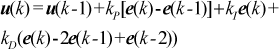
5.1 PID Controller for Tracking Trajectory
The ideal velocity impulse (Δυ
i
(i = 1,2…M)) is obtained from the ideal optimal approach trajectory. To simplify design of the controller, the Δυ
i
are transformed to constant thrust force


5.2 Optimization and Distribution of Tracking Control Force
The purpose of this part is to optimize and distribute the control force to the space tether and thrusters, but the tethered space robot is very complex for the special characteristics of space tether. So simple assumptions are given as follows:
Space tether is massless and inextensible.
Tension force is supplied by releasing or retrieving tether from the rolling motor.
The tether should supply tension force along a straight line for connecting the robot platform and operation robot.
The tether's influence on the robot platform is ignored.
The coordinated control scheme of the operation robot is shown in Figure 5. Otxtytzt is the target orbit frame,

The coordinated control of the operation robot
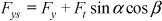
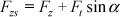
Fx, Fy and Fz are the control force of the PID controller in Otxtytztframe. Assume Ft is the tension force of space tether after distributing control force. Meanwhile, Fxs, Fys and Fzs are the distribution control force of thrusters in xt/yt/zt three directions, so it can be concluded that:

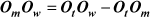
The unit vector of tether direction is obtained according to the geometric relationship:


According to the actual situation of the operation robot for approaching the target, the out-of-plane (zt direction) motion is ignored. So the cost function of control force optimization and distribution is selected as follows:

where w1 and w2 are weight coefficient. It can minimize the cost function while distributing the control force to space tether and thrusters. The weight coefficients w1 and w2 are decided by the release direction of the operation robot. If the operation robot is released in the xt-axis direction, 0 <w2 <w1 <1. If the operation robot is released in the yt-axis direction, 0 <w1 < w2 < 1. The primary methods include genetic algorithm [27–29], ant colony algorithm [30] and simulated annealing algorithm [31–32]. The simulated annealing algorithm is adopted for control force optimization and distribution in this article. The control force is optimized and distributed in discrete time points, and the continuous distribution of control force is achieved through polynomial fitting because of the low optimization speed of the simulated annealing algorithm.
The simulated annealing algorithm is derived from the solid annealing principle based on the Monte Carlo iterative method for heuristic searching, and has proved to be in theory a convergence for global optimization. Its control parameters include initial temperature T0, minimum temperature Tmin, iteration number n, annealing coefficient ξ and stopping condition. The flow of the simulated annealing algorithm can be described as follows.

If h≤P(yi|xi,Tj), order xi+1=yi, Jf(xi+1) = Jf(yi). Otherwise, order xi+1=xi, Jf(xi+1)=Jf(xi).
If the Metropolis sampling stabilization rule is satisfied, order i = 0, go to step 6. Otherwise, order i = i +1, go to step 2.
The Metropolis sampling stabilization rule is used to determine the number of tentative solutions at the given temperature. A fixed step number n is chosen as the inner loop termination rule at the given temperature; the inner loop is terminated, and the temperature is reduced.
The cooling schedule is taken as Tj+1 =ξTj, where ξ is an annealing coefficient.
5.3 Attitude Stability Strategy
The relative attitude interferential torque will be produced when the space tether exerts tension force to the operation robot. Therefore, the attitude stability is an important aspect of the coordinated control method. This article intends to control and stabilize the relative attitude using the time-delay algorithm through the reaction wheels of the operation robot.
The time-delay control method is mainly for dealing with unknown dynamics, such as uncertainties and disturbances without any explicit estimation [33]. The unknown dynamics contain model changes due to external interference. The idea of this method is to supply former period control, compensating the control changes due to the tether's torque interference.
The attitude dynamic equation of the operation robot is given by Eq. (30), where the interferential torque
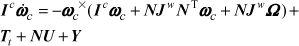
where the control compensation is

Eq. (30) can also be drawn:

where N = NT (NNT)−1 is the Moore-Penrose inverse matrix. Combining Eqs. (52) and (53) gives:

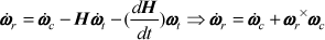
Eq. (25) shows the relationship between ωr and ωc. In order to satisfy
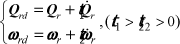
Where t1 and t2 are time constants, those constants express hanging velocity. It is possible to determine that t1> t2 >0, which means that the angular velocity changed faster than the relative attitude.
The relationship between ωr and Q can be expressed by the attitude kinematic equation:

where (Qr×)− = (Qr×)T[(Qr×)(Qr×)T]−1 is an arbitrary, generalized inverse matrix of Qr×. It is possible to obtain the relationship between
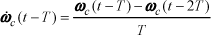
Combining Eqs. (54), (56) and (57), the final time-delay attitude coordinated control law is:

where Qr, ωr and ωc can be obtained by relative sensors, and the
The interferential torque is related to tension force, the connection point between the tether and the operation robot. Assume the distances between the connection point and the centroid of the operation robot are lx, ly and lz. The interferential torque

6. Examples and Numerical Results
6.1 Initial Conditions
Assume: the operation robot is approximately 10 kg, the robot platform is about 2000 kg; lx = 0.3 m; ly = 0.3 m; and lz = 0 m. X0 denotes the initial states and Xf is the final desired position.
X0 = (139.63m −0.0012m 0m −1.5m/s 0m/s 0m/s)T, Xf = (0 0 0 0 0 0)T. Qr0 is the initial relative attitude of the operation robot and Qd is the desired relative attitude. Qr0 = [1 0 0 0]T and Qd = [1 0 0 0]T,
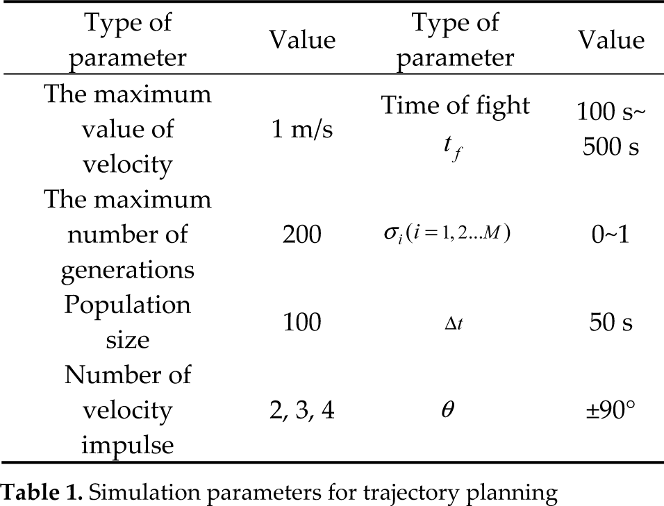
Simulation parameters for trajectory planning
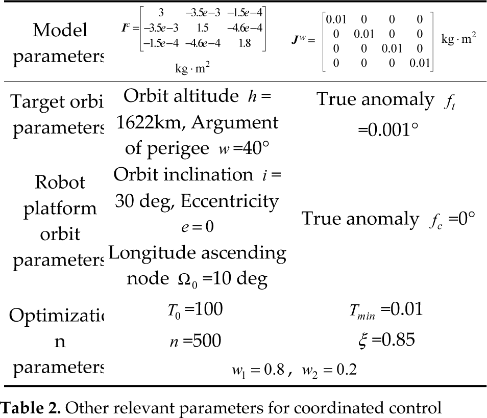
Other relevant parameters for coordinated control
6.2 Simulation for Optimal Trajectory Planning of Operation Robot
The operation robot has two and three velocity impulses imposed separately using NSGA-2 optimization algorithm, and the approaching time is 100 s ~ 300 s, which are estimated by relative distance and velocity at the initial time. Figure 6 shows the Pareto optimal solution set; the abscissa expresses the flight time and the y-axis expresses fuel consumption (total velocity impulse). One hundred optimal solutions are obtained from every simulation condition (two and three velocity impulses). We can see that the optimal solutions of flight time are concentrated between 100 s and 190 s in two-velocity impulse mode; otherwise, the optimal solutions of flight time are concentrated between 100 s and 300 s in three-impulse mode. The relationship between approach time and fuel consumption is one of inverse proportion. The operation robot consumes more fuel in three-velocity impulse mode than in two-velocity mode in the same flight time.

Pareto optimal sets
We select position “1” at 103 s; position “2” at 162 s; and position “3” at 185 s from Figure 6. Figure 7 shows the relative trajectory of the operation robot based on the two modes. The relative trajectories at different approach times are similar. However, the movement trend in the y-axis direction (radial direction) in three-velocity impulse mode is much less than the x-axis movement in two-velocity impulse mode. Following increase in flight time, the movement trend in the y-axis direction becomes larger. The out-of-plane movement is nearly zero and can be ignored.
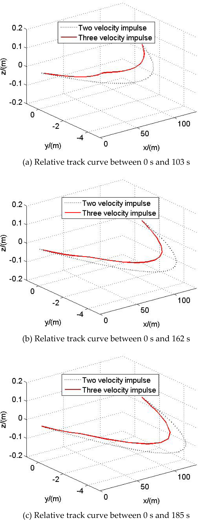
The relative track of two modes for TSR
This paper ignores the out-of-plane view angle because the movement trend in the z-axis is less obvious than in the other two directions. Figure 8 shows the view angle curve of the operation robot based on the two velocity impulse modes. The view angle curve is similar, with two modes at position “1”, “2” or “3”. The view angle will decrease with the increase number of velocity impulses, which is useful for the working of relative sensors.

The view angle curves of two modes for TSR
From the above simulation, it can be seen that the NSGA-2 optimization algorithm is useful for trajectory planning based on velocity impulse of TSR. The fuel consumption is always contrary to the approach time. However, the fuel consumption is not contrary to the relative view angle. Therefore, the optimal trajectory can be selected from the Pareto optimal solution set according to special task requirements. The amplitude of velocity will decrease when the approach time increases. The in-plane view angle will decrease when the number of velocity impulses increases, which is useful for the relative sensors.
6.3 Simulation of Coordinated Control Method for Tracking Optimal Trajectory
This paper presents a coordinated control method using thrusters, space tether and reaction wheels in the process of tracking the optimal trajectory. Taking the optimal trajectory of two-velocity impulse mode as an example, its approach time is 162 s. The ideal velocity impulses are 0.6439/−0.1565/0 (m/s) in t0 =0 and 0.856/−0.1565/0 (m/s) in tf =162 s. This velocity impulse can be transformed to standard control force by Eqs. (40) and (41). However, the error between velocity impulse and standard control force exists, and there is a measurement error and other errors. Therefore, the PID controller should be designed. It is assumed that the real-time position measurement rrel is r ± 0.05r (r is the true position). All the control force can be expressed in the otxtytzt frame in order to illustrate the effect on saving the thruster fuel using space tether.
Figure 9 shows the comparison between ideal trajectory and tracking trajectory. The operation robot can track the optimal approach trajectory effectively using this coordinated control method. Figure 10 shows the states of the space tether. The states contain in-plane angle, out-of-plane angle and releasing length. The out-of-plane angle φ is nearly zero because of reduced out-of-plane movement. The in-plane angle θ starts from 90° and moves to 79°, which can reveal the approach characteristics of the operation robot in this numerical example. The states of the space tether can express the approach trajectory of the operation robot in another way.

Comparison between ideal trajectory and tracking trajectory

The states of space tether
Figure 11 shows a thruster force comparison between single PID control and coordinated control. Fx, Fy and Fz are thruster control force in the xt - axis, yt - axis and zt - axis directions, respectively, using a single PID controller. Fx1, Fy1 and Fz1 are transformed standard thruster control force from an ideal velocity impulse. fx, fy and fz are the distributed control forces of the thruster using coordinated control method. Fx and Fx1 are different to a certain extent, due to the velocity transformed error, measurement error and other errors, which are the same as in the other two directions. The positive force of fx can be decreased to nearly zero compared with Fx using this coordinated orbit control method. As a result of the releasing mode, the thruster fuel cannot be saved effectively in the other two directions. However, the thruster fuel consumptions of the xt - axis direction are of primary importance among the total fuel consumptions. Therefore, the thruster fuel can be saved effectively using the coordinated control method. The space tether can only supply tension force, which can be also be seen from the simulations.

Thruster force comparison between single PID control and coordinated control
Figure 12 shows the tether tension force and the interferential torque produced by the space tether. In the periods of 0 s~30 s and 150 s~162 s, the space tether can supply tension force that can save thruster fuel in the xt - axis direction. Therefore, the operation robot can be influenced by the interferential attitude torque at the same approach time. The interferential attitude torque remains between −0.3 N·m and +0.3 N·m.
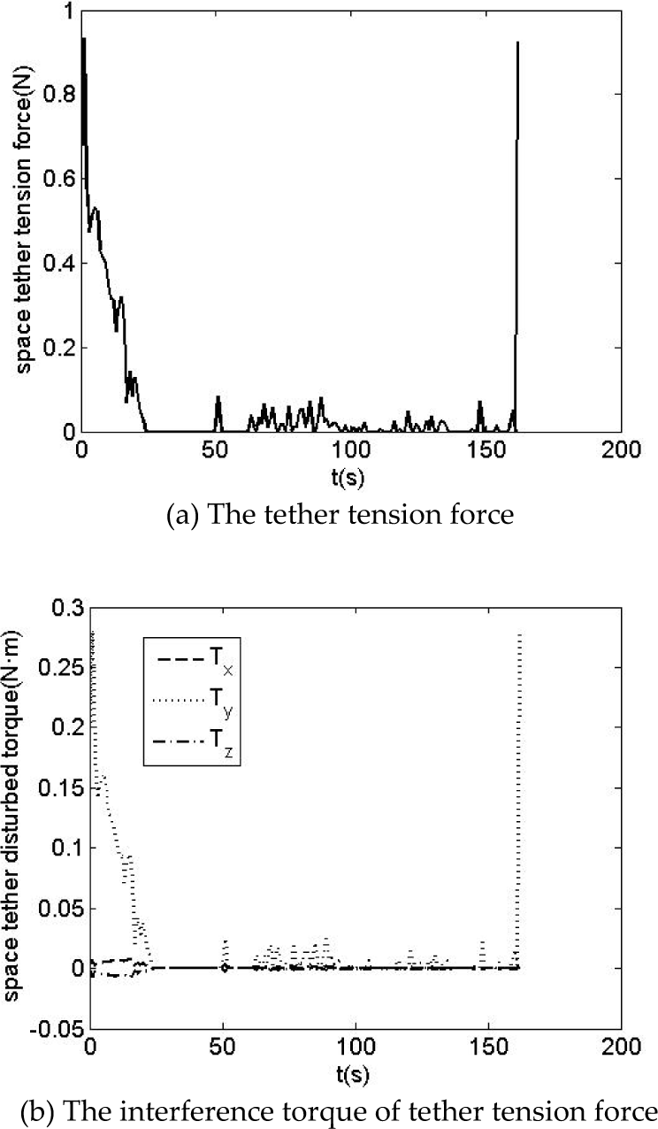
Tethered tension force and its interference torque
Figure 13a shows the relative attitude angle controlled by reaction wheels using the coordinated attitude control method. At the early stage, the roll angle φ1, pitch angle θ and yaw angle Ψ1 are held between −2° and 2°. Finally, the relative attitude angles are stabilized between −0.5° and 0.5°, which can satisfy the attitude requirement. Figure 13b shows the relative angular velocity of the operation robot. The results show that relative angular velocity is maintained at less than 0.015 rad/s after using the coordinated attitude control method, which satisfies the stability requirement.

The relative attitude and relative angular velocity for tethered space robot
The attitude control torque is shown in Figure 14a, the angular velocity of the reaction wheels are shown in Figure 14b. The reaction wheels are stable after 30 s. The corresponding attitude control torque is supplied by reaction wheels before 30 s. Hence, the robot's attitude can be stabilized between 0 s and 100 s.

The attitude control torque and angular velocity of reaction wheel
In this simulation, we select the same special circular orbit for the target and the TSR. If the target orbit and TSR orbit are different, or the target and TSR are located in the same ellipse orbit, the distance between target and robot platform should be measured in real-time with the help of the sensors of the robot platform, which may result in changing the direction of the tether tension force. Furthermore, the yt-axis or zt-axis direction thruster fuel may be saved through tether tension force. However, the rule of the simulation results is the same if we transform the above initial conditions.
It can be concluded that the proposed coordinated control method can make the operation robot track the optimal trajectory effectively based on velocity impulses. This transformed optimal velocity impulse can be used to standardize control force, and the PID controller can be designed with consideration for the position measurement error. Then, the control force can be distributed to the space tether and thrusters. The interferential torque produced by the space tether is stabilized using the attitude stability method based on a time-delay algorithm through reaction wheels in the interim.
7. Conclusions
First, this paper studies a multi-objective optimal trajectory planning method based on velocity impulses using an NSGA-2 algorithm. Then, the article proposes a coordinated control method for tracking the optimal trajectory. For optimal trajectory planning, the optimal Pareto solution sets are calculated for two- and three- impulse modes in periods of 100 s ∼ 300 s. The relative trajectory and view angle of operation robot are simulated at three special positions for two-velocity impulse modes. The simulations show this trajectory planning method can clearly reveal the relationships among fuel consumption, approach time, view angle and imposed number of velocity impulses. A suitable optimal trajectory can be selected according to special task requirements. For the coordinated control method, the paper designs the PID controller combined with the transformed standard ideal control force. Thus, the ideal control force is obtained. To save thruster fuel, the ideal control force is optimized and distributed to the space tether and thrusters. The interferential torque of the space tether is stabilized using the attitude stability method based on a time-delay algorithm through the reaction wheels. Simulation results show this coordinated control method can make the operation robot track the optimal trajectory based on velocity impulse, and maintain relative attitude effectively.
Footnotes
8. Acknowledgments
This work was supported by the National Natural Science Foundation of China (Grant No: 11272256, 61005062) and the Doctorate Foundation of Northwestern Polytechnical University (Grant No: CX201217).