
Abstract
Today's and future space missions (will) have to deal with increasing requirements regarding autonomy and flexibility in the locomotor system. To cope with these requirements, a higher bandwidth for sensor information is needed. In this paper, a robotic system is presented that is equipped with artificial feet and a spine incorporating increased sensing capabilities for walking robots. In the proposed quadrupedal robotic system, the front and rear parts are connected via an actuated spinal structure with six degrees of freedom. In order to increase the robustness of the system's locomotion in terms of traction and stability, a foot-like structure equipped with various sensors has been developed. In terms of distributed local control, both structures are as self-contained as possible with regard to sensing, sensor preprocessing, control and communication. This allows the robot to respond rapidly to occurring events with only minor latency.
1. Motivation and Overview
Space exploration missions are of special interest, e.g., in addressing physical questions or ascertaining whether a certain planet has ever had an environment that was able to support life. Even so, Mars is currently a focus of space exploration – NASA recently stated that they had found ice deposits close to the moon's north pole using imaging radar. To be more specific, indications of water ice were found in more than 40 craters ranging in diameter from one to nine miles “which will give future missions a new target to further explore and exploit” [23]. Besides exploration scenarios, robotic assistance can be useful in many applications, such as on the International Space Station in taking over tasks which can become too dangerous for astronauts, or in building space habitats to create permanent settlements for humans to explore different destinations.
Although wheeled and tracked vehicles are usually more energy-efficient and easier to control, legged systems have access to a wider range of terrains as they are capable of applying forces in a non-continuous way in numerous directions and magnitudes within their designed workspace [28], as opposed to continuous tracks, which is useful for exploration scenarios in rough environments. In particular, if a robot's outer appearance is humanoid, it will have the ability to linger within workspaces designed for humans [4] and use the same tools. Stoica et al. discusses in [30] the design criteria for robots which could perform the assembly of long-term habitats. If the robot is provided with appropriate hardware, it may even be empowered to use its limbs for more than walking, e.g., for manipulation or sensing tasks.
This paper describes an ape-like robotic research platform (see Figure 1) incorporating active spine and feet with increased sensing capabilities which, if employed on the robotic system, can improve its locomotion and mobility characteristics on rough terrain. All the sensor data coming to the robot are locally processed by electronic systems which are integrated into its structure. The robot's design is inspired by chimpanzees so as to allow the system to perform quadrupedal and bipedal locomotion in order to meet both the mentioned application areas. While the control of higher levels, like image processing, knowledge representation and planning, etc., are highly interesting research topics, we focus on the application of distributed sensor preprocessing and local control loops at lower levels.
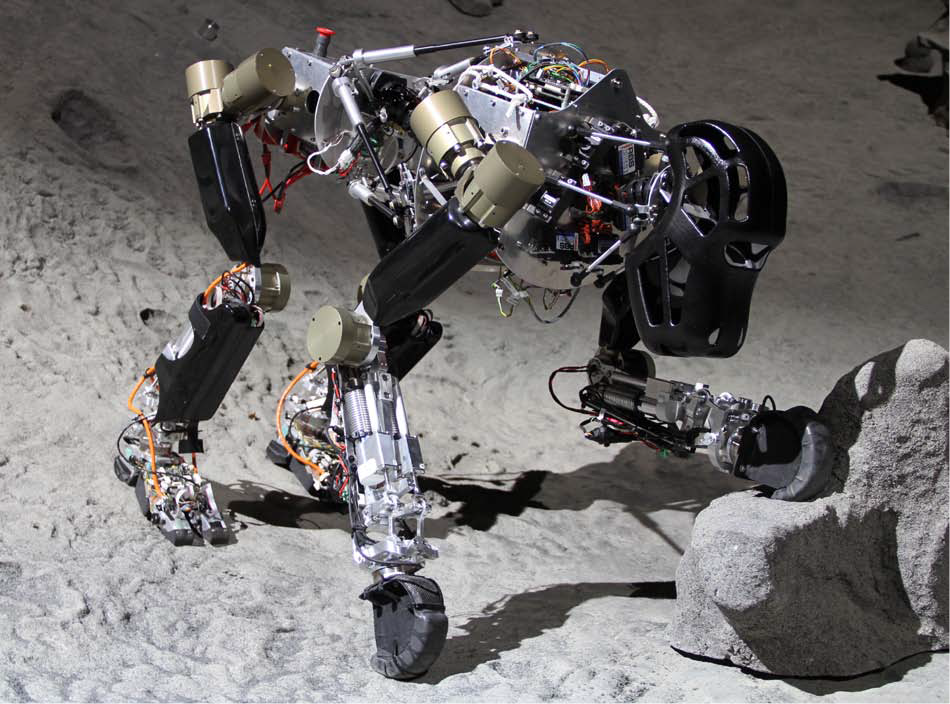
Photo of the presented ape-like robot with artificial spine and sensor feet
As stated above, legged robots are able to provide a higher degree of flexibility in their locomotion system. A variety of systems that mimic the locomotion patterns of their natural counterparts have been successfully developed by a number of research groups, such as [25] and [18], to name only a few.
Force-controlled multi-legged robots with single-point- contact feet (SPCF), like the Scorpion robot [28], have demonstrated their cross-country mobility. The usage of spherical-shaped feet can be seen in robots like SpaceClimber [3] and LittleDog [22]. Such feet have the advantage of providing traction at any contact angle. Damping capabilities are not included in the feet, but are realized in the lower leg with a compliant degree of freedom. The benefit of multi-point-contact feet (MPCF) is ultimately not great for multi-legged robots, which have the intrinsic ability to generate a stable stance by selecting an appropriate walking pattern, even with single-point-contact feet. Consequently, for the sake of simplified design, weight and control, most multi-legged systems neglect the foot issue. In considering the desire to receive various information from the feet, one gets more limited integrating sensors as the structure becomes smaller. In contrast, MPCF can have advantages for multi-legged locomotion as well, since a better adaptation to difficult terrain leads to increased traction.
[9] introduced a new foot design for a two-legged robot, in which one spike-like structure is integrated in each corner of a rectangular-shaped foot. The foot has one DoF in the ankle joint and adapts its four main contact points to compensate for small irregularities of up to (2). One drawback is that the function of this foot cannot be applied on deformable surfaces. Most bipedal robots, like Asimo [26] and Lola [6], have MPCF attached to a passively constrained and/or actuated ankle joint in order to realize a stable stance by spanning a global support polygon.
Existing multi-legged walking robots featuring MPCF, like Titan [13], Roboclimber [1] and the foot described in [32], are introduced with passive adaptation mechanisms in the feet to exploit these benefits. Initially, the BISAM robot was equipped with spherical-shaped feet until a larger support area and greater friction could be achieved. Thus, MPCF were installed including, a six- DoF force/torque sensor [2]. The Aramies robot has actuated claws which are used to grip at steep inclinations. Each claw is equipped with five pressure sensors and an IR-distance sensor for ground contact detection [11]. While the mentioned MPC-feet may be sufficient for effective quadrupedal walking, stable and efficient locomotion for bipedal walking are also desired for the system presented here. Since the combination of these two locomotion modes is a focus of this project, new active MPCF suitable for both locomotion modes (with increased sensing capabilities) had to be developed. Fukuda et al. presented a robot able to perform both locomotion modes [17]. Unfortunately it is unclear whether the robot has any sensors applied in the feet structure.
Although some of the mentioned multi-legged systems have one passive or active degree of freedom (DoF) in their body, structural enhancements are necessary in order to achieve greater mobility and allow alternative motion sequences. The majority of biologically-inspired walking systems have rigid structural components for their bodies. As a consequence of these rigid connections, the motion of most robotic systems appears static and restricted. In contrast, nature uses spines as central elements of vertebrates, for various purposes such as adding degrees of freedom, absorbing shocks and storing and releasing energy to increase efficiency.
At present, different robotic research groups are trying to introduce the concept of a spine-like structure into mobile robotics so as to take advantage of the above-mentioned characteristics. In general, there are two different approaches: using either a passive or an active connection between the front and the rear body. An example of a walking and climbing robot equipped with an artificial passive spine is given by Santos et al. [27]. [33] describes an active approach in the design of spine-like structures for multi-legged systems. Within the iCub project [12], a humanoid robot shaped like a child was designed featuring a three- DoF differential-based mechanism to increase the range of motion of the upper body. Mizuuchi et al. introduced a man-sized humanoid robot with a flexible spine [21]. A similar tendon-based approach is used by Holland et al. in their developments [15]. However, these systems are nonetheless implemented as rather complex designs or else equipped with serially-aligned rotational actuators. We present an actuated spine-like structure based on a hexapod platform integrating sensing capabilities into its subsystem.
This document is structured as follows: The mechanical design of the proposed robotic system, including its subsystems and the required constraints, is described in Section 2. The whole design has led to an increased set of sensors, perceiving the system's state and its interaction with the environment. This results in the need for local sensor preprocessing and local control, as presented in Section 3. Next, Section 4 gives an overview of the control strategies currently being implemented. Finally, a selection of experiments that were performed are described in Section 5, followed by a discussion of the obtained results and the outlook regarding possible future work.
2. System Design
The current prototype has a total of 28 active and six passive DoFs excluding the head, as depicted in Figure 2. Consisting of four brushless DC (BLDC) actuator modules for the shoulder/hip joints and the knee joint, the upper legs are all built in an identical fashion, whereas the rear legs additionally possess a three- DoF ankle joint with an attached MPCF instead of a SPCF. Two of these additional DoFs are actively controlled (more details are given in section 3.3), while the ankle yaw angle and all of the MPCF DoFs move passively. The passive ankle yaw angle is a trade-off between mechanical ankle joint complexity and compliance to external forces. The front leg limbs are also 40 longer than the rear ones.
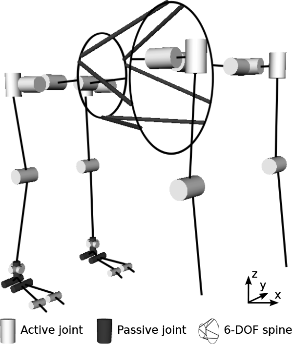
Schematic drawing of the robot's DoFs in zero position. The six- DoF hexapod structure of the active spine connects the front and rear parts of the body
The maximum height in a four-legged posture is 750 and around 1300 in a bipedal posture, including the head. The shoulder is 440 wide and the hip is about 350. Depending upon the artificial spine, the distance from the first axis of the shoulder to the hip joint varies between 500 and 540.
The system as displayed in Figure 1 has a weight of 22, including rechargeable lithium polymer batteries of 44.4 with 2.4. The power consumption of the system while being carried by a support structure in the walking posture is 48. When the robot stands on a flat surface carrying its own weight, the power consumption rises to 51.4. The front and rear of the body are each equipped with an inertial measurement unit.
Fig. 3 shows a block diagram of the electronics (nodes) and sensors within the system. The motion control unit (MCU) is the central node which generates the desired joint poses, sends them to the various joints, and handles incoming motor and sensory data. Some sensors, such as IMUs, are connected directly to the MCU, while others are preprocessed by local nodes. The communication within the subsystems is organized as a daisy chain, where all the nodes can communicate with each other.

Block diagram of the electronics and sensors within the system
2.1. Leg Joints
The first four joints of each leg are built identically. In previous work, the basis for these leg joints was laid out in [10]. The developed joint has the dimensions 65 × 90 (L) at a weight of 430. Even so, while some adjustments regarding size and weight have been made, the key properties remain the same. A hollow shaft leading through the main axis of the actuator allows us to route wires through the structure. Each joint bases on an ILM50-8 RoboDrive brushless DC motor combined with a HarmonicDrive reduction gear. As for the rotor and the stator, components from RoboDrive were chosen since these have already been successfully space-qualified [14]. The HarmonicDrive gear has also shown its performance in space applications [34].
Powered with 48 DC, the RoboDrive motors deliver a nominal torque of 0.28 and a peak of 0.9 before gear transmission. Based on previously-estimated torques, the first and the knee joints are equipped with 80:1 reduction gears, in comparison to the second and third joints which have 50:1 reduction gears.
Thanks to the consistent implementation of distributed control, each actuator is controlled by its own electronic system and the incoming sensor data are (pre-)processed locally. The actuator electronic system is equipped with a Spartan6 Field Programmable Gate Array (FPGA), able to measure all three phase currents, the supply voltage, the temperature and the angular motor position.
2.2. The Foot, Ankle Joint and Lower Leg
The developed MPCF consists of five rigid bodies (see Figure 4), whereas the connections are monitored by angular encoders. Just like its biological counterpart, the rigid core of the artificial foot is supported by multiple layers of different materials for added damping and traction. The foot has dimensions of 195 × 94 × 80 and a total weight of 350. In [8], a more detailed description of the design and its structure is given.

As shown in Figure 4, it embodies three printed circuit boards, two of which are sensor processing electronics with an STM32 microcontroller. Its analogue front-end is composed of two multiplexers, an amplifier and an analogue-to-digital converter (ADC) to measure up to 49 voltage differences. In the following, this sensor electronic system will be referred to as the ‘multiplexed data acquisition’ (MDAQ) board. The size of the MPCF makes it also possible to equip the foot with multiple sensors. An optical distance sensor is mounted in the heel, offering the opportunity to reduce the velocity prior to an expected ground contact. A three-axis accelerometer allows it to measure gravity and other accelerations, such as those occurring during a collision or slippage. The spatial distribution of forces acting on the sole of the foot is measured by a pressure-sensing array consisting of 49 force-sensing resistors, introduced in section 3.2. With this array, a spatial resolution of 0.34.5 can be achieved. To be able to measure the total forces and torques with a high degree of accuracy, on top of each front and rear foot an ATI nano 45 six- DoF force/torque sensor is mounted. This sensor is also used as a mechanical interface to connect all the feet to the lower legs, allowing the system to perceive its complete ground interaction forces. The front feet are hook-shaped and equipped with tape switch sensors to allow a spatial resolution of the applied force.
The rear lower legs include a double-lever mechanism driven by two linear actuators and a local FPGA electronic to control the ankle joints. Two Faulhaber 2250S024BX4 BLDC motors with 10:1 reduction gears drive lead screws and spindle nut mechanisms with 2 per turn. With this double-lever mechanism, two DoFs are controlled (pitch and roll), while the third DoF is kept passive (yaw). All three DoFs are monitored by absolute angular encoders.
The ankle joints' range of motion is 130 for pitch, 50 for roll and 40 for yaw. The maximum angular velocities at 48 are 160 for pitch motions and 190 for roll motions. The lower leg has a length of 250 and a weight of 1200.
2.3. Spine Design
The major goal of the artificial spine's development was to add extra DoFs to the robot's torso while keeping the design simple and robust. The chosen design follows the principle lying behind a Stewart platform. Figure 5(a) shows the spine with its mechanical interfaces for the robot's limbs as well as compartments for the rechargeable battery, control and power electronics. The spine is driven by six Faulhaber 2444S024B BLDC motors with 246:1 reduction gears and angular encoders. 20 levers connect the six motors with the 250 -long rods to realize a hexapod structure using rotational actuators. The diameter of the spine is 305 at the front and 190 at the rear. The developed torso and rod prototypes are depicted in Figure 5. The weight of the spine module, including motors, levers, rods, casing and electronics, is approx. 3.3.

Different aspects of the proposed active spine subsystem
The resulting workspace presented in Figure 5(c) implies an increased range of motion for the limbs, which are attached to the spine. Using different lever arm lengths on the motors, the range of motion can be either increased or decreased. On the left-hand side, the workspace is shown in y/z coordinates, such that the hip can move to the left or the right (y-axis) and up or down (z-axis). The central image shows the side view of the range of motion, whereas the distance between the hip and the shoulder can be changed (x-axis). On the right-hand side, the top view is displayed.
Within the spine's structure, only tension and compressive loads can occur. Therefore, six Burster 8411-500 one- DoF miniature load-cells are integrated into the spine rods (see Figure 5(b)) which produce a difference voltage proportional to the force applied along those rods. An MDAQ board is used to measure these voltages. In combination with the current spine pose, the six forces are transformed into a force and torque vector. The details of this transformation are explained in section 3.4. A more detailed description of the proposed artificial spine can be found in [19].
3. Sensory Preprocessing and Local Control
This chapter presents a selection of approaches to sensor preprocessing and local control which exploit distributed computational intelligence. For this purpose, the whole system can be seen as a set of nodes, whether control, motor or sensor processing nodes or combinations thereof. These nodes are connected via a low voltage differential signal (LVDS) bus and each node (whether FPGA or microcontroller-based) comprises the same communication and configuration interface. Hence, each node is able to transparently communicate with every other node in the system such that feed-forward information processing and local control loops can be consistently established.
3.1. Joint Control
In all the joint control implementations, incremental encoder signals – which are initialized at startup by means of absolute angular sensors – are used to calculate the actual positions and speeds of the motors. With this information, different control mechanisms generate the pulse-width modulation (PWM) outputs for commutation [16]. A hall sensor-based commutation strategy is utilized to switch the MOSFET's gates for the three-phase full bridge inverters. To avoid damage to the hardware, safety monitors are implemented which turn the leg and ankle joint motors off if the measured angles exceed a pre-configured limit. This safety feature is not required for the spine because its motors are allowed to rotate without hardware limitations. In addition, a current measurement has been implemented to estimate the load torque of the actuators.
In order to keep the motor control as self-contained as possible, the inverse kinematics for the spine and the ankle joints are determined locally. In the ankle joints, the motion commands from a higher-level logic and the angle offsets of the virtual springs (VSs) calculated by the foot electronics (see Sec. 3.3) are converted into the corresponding motor positions by a VHDL (Very High Speed Integrated Circuit Hardware Description Language) implementation. In contrast to the ankle joint, a Microblaze softcore CPU with a floating point unit is embedded into the spine's control FPGA to handle the inverse kinematics tasks.
3.2. Perception of Interaction Forces
The forces exerted onto the sole of the foot compress the hyperelastic material of the force-sensing resistors of the sensor array. Because of their low cost and ease of use, the FSR400 family from Interlink has been selected for this purpose. During the measurement process, the voltages at each row and column of the resistor matrix have to be determined; further details can be found in [8] and [31]. Throughout the entire process the voltage differences are checked to identify short circuits and possible sensor failures. Where a short circuit occurs, it only affects the sensor elements in the same row, not the rest of the array. More difficult to detect is a failing sensor in the absence of any sign of a short. At the point when other information, like the expected force at a certain time or the total force measurement of the force/torque sensor, is available, a probabilistic approach might be adopted to detect non-responsive sensors.
The conductance or resistance of the FSR is monotonically but nonlinearly dependent on the exerted force. After having derived a model of this relationship, the characteristic of a uniformly loaded 4 × 3 sensor array has been acquired. The calculated sum over all the components (Figure 6(a)) matches the reference load with at least 10 accuracy after settling. In a different experiment, a snapshot of the spatial force distribution of both the foot sensor array and a commercially available Tekscan pressure sensing foil was taken while the robot was standing on a flat surface. The results are shown in Figure 6(b), where the dark areas denote higher pressure and the bright areas denote lower pressure (or no pressure at all). Also marked is the calculated centre of pressure (CoP) as obtained from each sensing system. The CoP is determined by the sum of taxel position times the sensed force divided by the sum of all the measured forces.
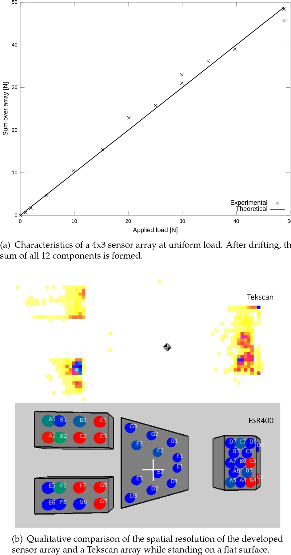
Experimental results of the FSR400 sensor array
Based on the array, each rear foot electronically calculates a local support polygon. For its determination, the current coordinates of the force-sensing resistors with ground contact are needed. To reduce the amount of data, only those vertices which are actually needed to fully describe the measured support polygon are sent to the central processing node. By this, the amount of data is reduced to a third.
3.3. Implementation of Virtual Springs
During quadru- or bipedal locomotion, the MPCF have to be placed such that the area of contact is maximized. This also maximizes traction with the ground, which in turn reduces slippage during movement. Furthermore, the ankle joint and foot have to absorb shocks during touchdown. In the case of small obstacles with respect to the area of the sole, the passive DoFs of the MPCF are sufficient for this task. For certain obstacle sizes or slopes, however, the ankle joint DoFs have to be adjusted to achieve the maximum area of contact. Therefore, VSs are integrated into local foot control. VSs emulate real spring-mass-damper systems by processing measured forces or torques and adjusting the actuating variable (e.g., angular displacement) accordingly. The presented concept is also valid for other tasks besides the example given here. Other research groups [7] have implemented similar mechanisms for impedance control.
The differential equation 1 defines a virtual torsional harmonic oscillator.


For a control loop, this differential equation can be rewritten in discrete form using the finite difference method. The first derivative takes the form

This VS-mass-damper system exhibits three free parameters. A reduction to two parameters is achieved if the damping constant k is set such that the system is critically dampened (see eq. 3). Under the assumption that the remaining parameters have been adequately chosen, this constraint prevents the oscillation of the VS. The stiffness of the virtual pitch spring is adapted with respect to the current state, since it is assumed by the higher-level control. This allows the ankle joint to flexibly adapt itself to the ground at touchdown and carry the robot's weight during stance. Experiments involving stepping on an obstacle and the parameter set are presented in Sec. 5.
3.4. The Spine as a Force/Torque Sensor
In this section, the necessary mathematical calculations to gather information about the forces and torques at the spine subsystem are described. The required information of the spine's pose is sent from the spine control device to the sampling MDAQ device. The following calculations are valid only if the spine's pose can be considered to be quasi-static during the force measurements. Figure 7 shows an example of one force vector and one torque vector for rod i. Knowledge about the forces

Schematic overview of the spine and possible force and torque vectors for rod i


For a static configuration of the spine, experiments with known reference forces have shown that the force torque vector is correctly derived. In the case of an altered spine configuration, the observation of a high correlation between
Components of the sample mean correlation matrix of the spine force torque vector recorded over 10 walking cycles

4. Walking Control
The biologically-inspired control approach implemented to actuate the robot's locomotor system utilizes a composite of postural behaviour and a central pattern generator (CPG), as described in [29]. The aim of the walking control is to coordinate the different subsystems to generate the motion patterns for walking, climbing, etc., and to react to events which cannot be handled locally. In addition to this, local control loops are used in this robot.
For the motion control, an electronic system has been developed with an Overo Gumstix board as the central component. The Gumstix board used in our system features an OMAP3530 using a 720 ARM Cortex A8 core. In addition, it is equipped with 512 Byte NAND-Flash, 512 Byte DDR memory, a microSD card slot and a WiFi module. This node executes a Linux kernel which handles the multi-threaded control program.
In order to use this board within our system, two additional boards have been developed. The main board hosts a Xilinx Spartan6 FPGA which acts as a bridge between the Gumstix board and some peripheral components, such as Ethernet and UARTs. Another task for this FPGA is to provide an interface for communication with up to eight different extension boards. The extension board currently in use provides LVDS interfaces for communication with all the legs and the spine. Additional RS232 channels, RS485 and GPIOs are used to connect to peripherals, such as IMUs and a relay board.
In the following section, the walking gait with the handling of force/torque sensor data is presented. Section 4.2 shows the body shifting motion which is used to increase the stability margin.
4.1. Reactive Control of Walking Gait
In the control program, one thread with high priority calculates the desired joint angles, while low priority tasks such as the calculation of the global support polygon are handled by other threads. Interrupt-triggered command handlers in blocking threads handle incoming data from within the robot or the controlling computer. Smooth control at the joint level is achieved without hard real-time support in the operating system, while jitter of the control commands is compensated in the networked motor-controllers [16].
The system's walking motion is a statically stable gait, always keeping the projection of the centre of gravity (CoG) inside the support polygon created by the ground contact points. In [20], different footfall sequences are analysed with respect to their stability margins, such that one of the theoretically possible sequences is found to have the best stability for an idealized walking system. According to [20], this gait (“crawl”: footfall sequence is front-left, rear-right, front-right, rear-left, as illustrated in Figure 8) is the common walking pattern observed by Muybridge in nature for the low-speed locomotion of quadrupeds. Configurable periods with all four legs on the ground allow the robot to prevent disturbances due to unexpected ground contact.

Phases of the legs during crawling gait: front-left (FL), front-right (FR), rear-left (RL) and rear-right (RR)
With this walking pattern, the robot's measured top speed on even terrain is 0.26. The footfall sequence is modified in the implemented control software according to the requested walking direction. The swing phase and the transitions to and from the stance phase are implemented by stitching Hermite splines for the swing-up and swing-down phases (with matching goal and start states) together, as proposed by Bruce et al. [5].
The trajectory of the feet during a walking cycle can be configured by setting an origin for each leg's motion and an offset for the control point connecting the swing-up and swing-down phases. The length of the stance phase is derived from the duty cycle and the requested walking speed. The duty cycle defines the fraction of a walking cycle in which a leg is in the stance phase.
The implemented gait behaviour provides for the reactive handling of observed early-touchdown (ETD) events. If one of the decentralized sensor-data processors detects a strong force during the swing-down phase of a leg, ground contact is assumed and the desired trajectory of the leg is adapted. The thresholds which are used to detect ground-contact (
4.2. Static Stability for Crawling Gaits
This section describes the shifting of the torso to keep the centre of pressure inside the support polygon during a statically stable crawling gait. Before a leg enters the swing phase of the gait, the main body will have already moved to the opposite side. The shifting motion may contain accelerations which increase the stability margin but which should also keep undesired accelerations to a minimum. As a simplification, we assume that the centre of mass (CoM) has a fixed position in the robot frame: moving the torso of the robot relative to the feet then has the same effect as shifting the CoM.
To generate a smooth trajectory for the main body, a method similar to the one proposed in [24] is used. There are four control points which define the targets for a trajectory of stitched Hermite splines. The values of these control points are predefined and represent a position opposite to each leg. If a leg enters a swing-up phase, the goal position of the CoM trajectory is changed to the control point diagonal to the following leg in the walking sequence, resulting in an eight-shaped curve, as shown in Figure 9(a). The stitched Hermite splines allow the system to change to another footfall pattern with a smooth transition to another CoM trajectory. The transition from forward to lateral right walking is demonstrated in Figure 9(b). Since the starting point of a Hermite spline is constantly reset to the current interpolated position, it is possible to change the goal position at any point in time without creating a jerky motion. Changing the goal state of the spline – timed to the swing phase of the gait – leads to increased acceleration, as shown in Figure 10. By accelerating towards a leg in the swing phase, the CoP is expected to move away from it.

Body shifting trajectory to increase the static stability of the crawling gait

The x -axis is pointing forward, while the y -axis is to the left. After
5. Experiments and Results
Having explained the overall system, this section presents the experimentally established results. The tests evaluate the state of the robot by comparing aspects of the data obtained in defined setups.
For the experiments presented, the duty cycle is set to 85, the cycle time to 7.5 and the foot swing height to 100. The control strategies, VS (sec. 3.3) and ETD (sec. 4.1) are always activated. The local control loop is performed at a frequency of 75. The spring constant D is increased from 0.00010.4 during the stance phase and decreased from 0.40.0001 during the swing-up phase, depending upon the expected state progress. It is 0.0001 during the swing-down phase while the moment of inertia I is always 0.1. These values were found empirically.
For each setup, data for 10 consecutive cycles were recorded and the created curves were based on the median. The walking cycle of the robot began on touchdown of the front-left leg, followed by the right rear leg, as previously depicted in Figure 8. In the robot coordinate system, the x -axis pointed forward, the z -axis upwards, and the y -axis to the left, as shown in Figure 2.
State information provided by the control software was used to synchronize the sensor data of the legs in two different ways. Either all the curves in one plot were synchronized to the same global walking cycle of the robot, or else the touchdown event of each leg was used to phase align the data from the leg in question. In the latter case, events during the cycles of different legs became more visible. The setups used for the experiments were as follows:
It should be noted that significant experiments with obstacle and deactivated local control loops cannot be shown, since the robot exhibits unstable behaviour and tends to tip over. It is arguable that the chosen parameter set favours the application of ETD and VS, and that by using different parameters other stable behaviours in their absence can be achieved. However, the parameters found so far allow the system to operate in a broader range of situations. The proposed adaptability through decentralized low-level and local-level control allows the system to mitigate obstacles without interference with the central electronics. Experiments performed with different parameter sets resulted in similar behaviour.
5.1. Virtual Spring
With the VS behaviour activated, as presented in section 3.3, it can be observed that the foot realizes maximum contact between sole and ground (see Figure 11(a)) in the presence of obstacles. The ankle adapts itself actively by decreasing the pitch angle and establishes ground contact with the heel while the forefoot is still resting on the obstacle. In contrast, the heel hovers over the ground if the VS is not active (cf. Figure 11(b)). The passive DoFs of the MPCF are not sufficient to deal with obstacles of this size (approx. 5).

The effect of the VS during the ObstacleRLToe setup. The local control loop of the VS allows the heel to reach the ground.
The VS actively influences the pitch and roll angles of the ankle joint based on the locally-perceived torque. Figure 12 displays the resulting ankle joint angles during the experiments. With no obstacle (Figure 12(a)), and while following the swing phase trajectories of the legs, the feet are always kept parallel to the ground. As one can see in Figure 12(b), the angles stay mostly unchanged compared to the previous setup – only the rear-left ankle is slightly changed. Sideways shifting of the CoG causes a varying roll angle.

Displaying the measured ankle joint angles roll and pitch for the two rear legs influenced by the VS. The robot cycle progress is annotated along the trajectory with grey numbers.
The differences in motion can be seen as soon as one of the rear feet hits the obstacle, as depicted in Figure 12(c). The rear-left ankle has a constantly decreased pitch. The obstacle is large enough to prevent the VS from expanding into the zero position during the swing phase. The rear-right ankle is similar to the undisturbed setups.
According to the plots shown, the proposed local control loop is working and does not interfere with the walking pattern if no obstacle is present.
5.2. Ground Contact Force
The robot uses its four feet to establish ground contact, where the only connection between foot and corresponding leg is the respective force/torque sensor. This allows the robot to constantly infer the resulting forces and torques generated by interaction with the world. Figure 13 displays
Visualizing the
Displaying the same dataset as shown in Figure 13, the
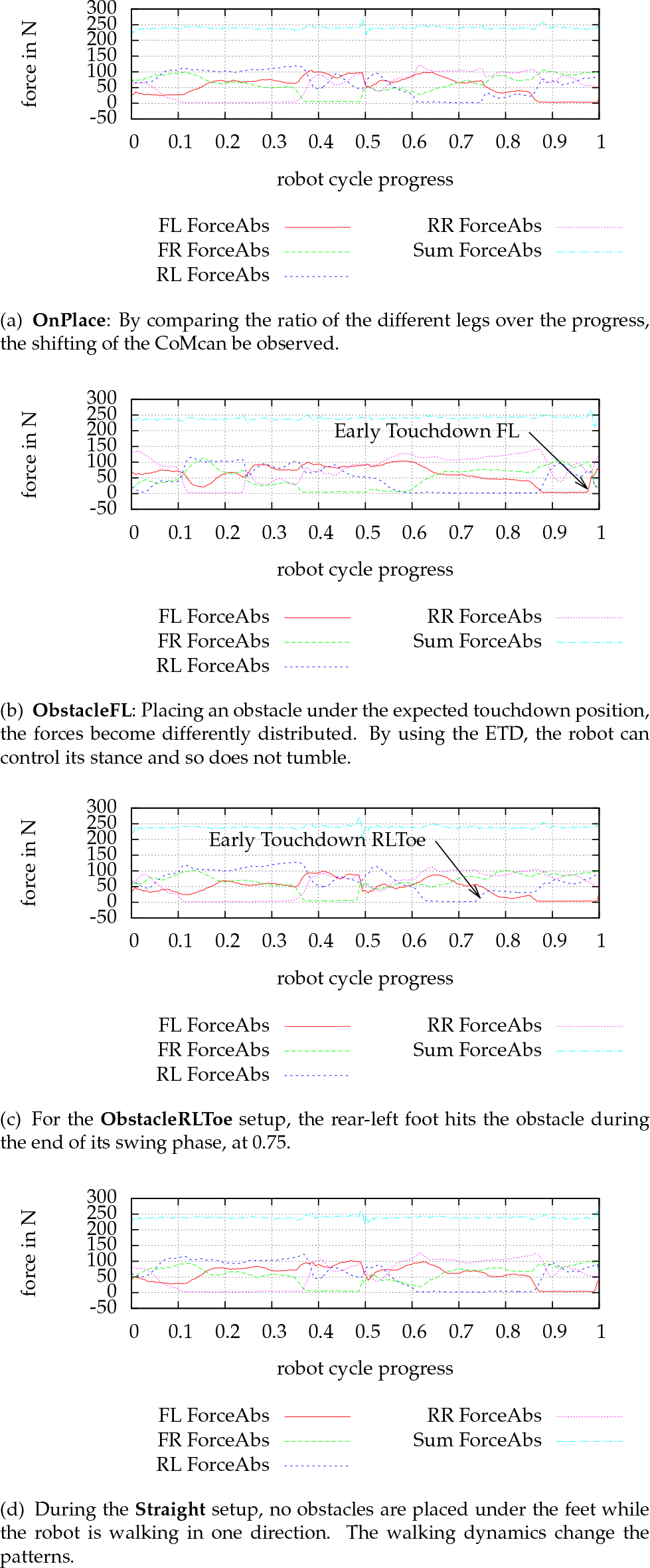
During undisturbed motion on a flat surface and without changing the direction of movement, the synchronized curves of the two leg pairs – front/rear and left/right – are similar, as shown in Figure 14(a) and Figure 14(d). They follow the same events during one robot walking cycle, delayed by the phase-offset between the legs. This symmetry (meaning how similar the curves of the pairs are) is an indication of how stable a manner a given pattern is executed over time. Unforeseen events will cause the symmetry of the behaviour to be disturbed. In Figure 14(d), it can be observed that the two rear legs have low contact forces during the beginning of their stance phases. This is caused by the deformation of the structure, whereby forces and torques are created by slight mis-positioning of the feet on the level ground. In Figure 14(c), due to the VS, no sharp rise in force on the rear-left foot is seen.

The
5.3. Centre of Pressure
A different setup is used to visualize the shifting of the CoG, as introduced in section 4.2. Therefore, the robot performs the shifting pattern without actually lifting its feet from the ground – only the CoG is actively shifted along the “8”-pattern. The measured

The measured force differences during a fixed stance on the ground. The robot cycle progress is annotated along the path in grey numbers.
As previously stated in Figure 9(a), the performed shifting movement is smaller in the direction of x than in the direction of y, caused by the foot-fall sequence of the crawling gait. The robot keeps more weight on its rear legs than on its front legs while moving. Besides the noisy motion along the measured trajectory, the forces (Figure 15) behave analogously to the trajectory of the CoG.
5.4. Exerted Torque in the Active Spine
The active spine of the robot allows for the measurement of the exerted forces and torques while the robot is moving (see Sec. 2.3). They can be gathered with a standard deviation of about 1/1 and a trueness of about 95. The forces are static for the investigated setups, where the absolute force

The different torque components and the additional
During the swing phase of the front-left and front-right feet, during the progress intervals from 0.35 to 0.5 and 0.85 to 1,
5.5. Moving the End-effector in Cartesian Space
Most of the higher-level trajectories of the robot are calculated in Cartesian space and are transformed into the joint space using the inverse kinematics inside the central electronics. Because each joint can have its own deviation from the desired angle during a motion sequence, the actual trajectory of the end-effector is displaced by the added errors of all the joints in the kinematic chain. Therefore, the two trajectories – the coordinates commanded by the central electronics before the application of the inverse kinematics and the coordinates obtained from the measured joint angles transformed with the forward kinematics – are plotted in figures 17–19. The walking cycle progress is annotated along the trajectory with grey numbers. The front-left leg is lifted once per walking cycle for 100.

In the OnPlace setup, the robot shifts its CoG without moving its feet forward, visible in the leg motion along the
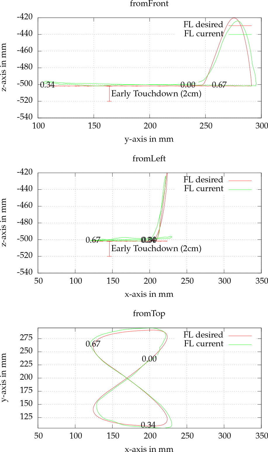
In the ObstacleFL experiment, the desired lowest level in the z -axis is shifted upwards
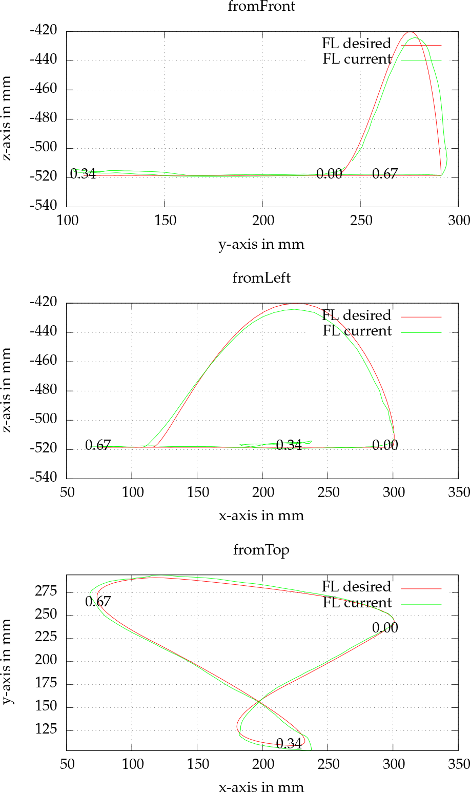
The forward motion in the Straight setting deforms the “8”-shaped leg trajectory
Figure 18 shows that the desired lowest level in the z -axis is shifted upwards by 2, caused by the ETD. The obstacle used has an actual height of 4.5, and the difference is due to deformation of the sole material of the foot and the mechanical leg structure prior to triggering the threshold. Not included here is the trajectory of the
The added forward motion in the
The different curves are transitioning smoothly between different states, resulting from Hermite spline interpolation (Sec. 4.1). The measured trajectories are not externally verified – mechanical deformations can cause further deviations.
6. Conclusion and Outlook
In this paper, a novel robotic system including two major subsystems – a sensory MPCF and an artificial spine – is presented. These two modules improve the overall locomotion and mobility characteristics for quadrupedal walking gaits. In combination with the implemented behaviours, such as early touchdown and VS, the robot's stability is successfully increased in encountering obstacles. Although the VS modify the desired joint angles of the walking pattern, undesired side-effects have not been observed. The additional behaviours allow the robot to cope with unexpected ground contact without any need to experimentally search for a working parameter set.
The present work seeks to take more of the available sensor and preprocessed data into account, allowing the system to be used in increasingly unstructured environments. In addition to this, the motion capabilities could be extended to other gaits with dynamic stability (e.g., zero moment point-based control [35]). Other locomotion modes, like bipedal walking, will be implemented to gain further insight regarding the reuse of functionality. Later revisions of the robot might also extend the existing structure with dexterous manipulation devices, thereby expanding the range of possible application areas. The integration of additional degrees of freedom to actuate a head with extended sensory equipment is intended.
Distributed computation is applied in various cases to the robot, which reduces central processing power requirements. Beyond this, local sensor processing reduces the amount of data needed to be sent to a higher control level. Additional force-based control approaches – in joint or Cartesian spaces – could be integrated into the system to mitigate unwanted effects in unstructured terrain or during dynamic locomotion. If possible, the distributed architecture should be further exploited in order to reduce the computational load on the central control board.
Due to the six- DoF force/torque sensor functionality, the load applied to the spine while interacting with the environment can be measured. Thus, it is possible, for example, to fuse spine and feet sensors to verify a detected touchdown or else apply VSs to reduce the influence of shocks. The design of the artificial spine simplifies the integration of mechanical springs and dampers by modifying the existing rods, which could be embedded to change the dynamic behaviour of the system. Furthermore, the integration of additional spine DoFs to support leg motion serves as ongoing work.
Footnotes
7. Acknowledgements
We would like to thank all the members of the DFKI Bremen Robotics Innovation Centre (RIC) and the Robotics Lab of the University of Bremen, who supported us in this work.
This work was undertaken within the Intelligent Structures for Mobile Robots (iStruct) project and partially within the TransTerrA project. These projects are funded by the Space Agency of the German Aerospace Centre with federal funds of the Federal Ministry of Economics and Technology (BMWi) in accordance with the parliamentary resolution of the German Parliament, grant no. 50RA1013 and grant no. 50RA1014 for iStruct, and grant no. 50RA1301 for TransTerrA.