
Abstract
This paper presents design of a climbing robot for inspection of glass curtain walls. The double-chamber structure enables the robot to climb over grooves on the glasses. In order to reduce the weight, both number and shape of the chambers are specially considered, and the pressure structure is optimized by FEA method. The statics models of different adsorption situations are also analyzed and deduced for the operational safety. In addition, design of the working arm and the wireless control system are introduced in detail. Finally, experiments of the robot are illustrated, including adsorption on different surfaces, vertical and horizontal groove-crossing as well as glass inspection. These experiments fully prove the theoretical analysis and demonstrate the climbing performance of the robot.
1. Introduction
During past years, over hundreds of climbing robots have been designed and tested, because such robots are potential alternatives of human labors for many applications, such as maintenance, inspection, welding or coat on high vertical structures [1]. Particularly, inspection of glass curtain wall, a widely used structure of high-rise buildings (Figure 1(a)), attracts more and more concern with urbanization of China, because falling glasses generated by accidental breaking are serious threats for people (Figure 1(b)). Needless to say, it is suitable for a climbing robot to conduct periodical checking on the glasses and the supporting structures.

Glass curtain (a) appearance (b) breaking accident
Pressure adsorption, mainly referring to vacuum adsorption and negative pressure adsorption, is the most common method to climb on the nonmetal surface. Relatively speaking, negative pressure adsorption has better performance on rough surface which results in leaking of the suction chamber, because generator of the negative pressure can deal with larger air flow under such circumstance. Therefore a climbing robot of negative pressure adsorption is simple in structure, strong in adsorption and great in adaptability. So far, such robots have been deeply researched and widely used.
The simplest robot of negative pressure adsorption has only one suction chamber. These robots, no matter wheeled or tracked, cannot work on curved surfaces or crossing obstacles on the surface (frame or groove, et al.). This disadvantage has been overcome by robots with multi-chamber structure, and some typical prototypes include City-Climber [2], Alicia3 [3, 4] and CROMSCI [5–7], each of which has 2, 3 and 7 chambers respectively. Besides, frame structure and legged mechanism also enable a pneumatic adsorption robot to cross obstacles or grooves. An example of the former is a robot specially designed for spherical shell of the National Grand Theater of China [8], and it has been further developed as Skycleaner3 robot which aims to work on curved glasses of Shanghai Science and Technology Museum [9]. While SADIE robot ([10, 11]) is another frame-structure prototype for non-destructive testing of various welds on the cooling gas ducts in the UK. On the other side, legged robots can be represented by biped Flipper [12], quadruped NINJA-I [13] and 8-legged RobugIII [11]. In addition, SkyBoy is also an inspiring prototype which is used for the glass facade of the control tower at the Guangzhou Airport [14]. This robot combines with advantage of different adsorption method: the operation on a glass plate is based on negative pressure principle, and the transition between the glass facades is implemented by a rail around the control tower. Another similar example is SIRUSc, a fully automated robot for the Fraunhofer headquarters in Munich [17], and the main difference of the robot is that its tail is placed on the building roof. In contrast to all designs afore-cited, a balloon-based robot, which neutralizes the robot weight by a balloon [18], may be the most innovative design. Although highly interesting, the actual design is almost not introduced by any paper.
In spite of this, these robots still have flaws which hinder the commercial application. Some of the robots are too huge and heavy for portable operations, and some of the robots can only work on a specific building. Moreover, frame-structure robots are relatively slow in the climbing speed, while legged robots are complex for the control. In contrast, this paper introduces a low-cost and light-weight climbing robot mainly based on off-the-shelves products. The paper is briefly structured as follows. The robot structure is firstly introduced in section 2. Then consideration of the chamber shape, the chamber number and detailed design of the chamber structure are discussed in section 3. The following content (section 4) covers adsorption analysis during the groove-crossing. After that, section 5 relates to selection of the driving motors. In section 6 and 7, the operational arm and the wireless control system are respectively illustrated. All deduce above is proved by experiments presented in section 8, and the final part of the paper demonstrates conclusion and future works.
2. Structure Overview
The robot is designed for China Building Science Academy (CBSA) that requires robotic inspection of glass curtain walls. On the curtains, numbers of plate glasses are divided by crossing grooves, and the width of each groove is not larger than 30mm (or the building appearance will be ruined). This structure is so-called “hidden frame glass curtains”.
Groove-crossing requires the robot to have at least two suction chambers for the reliable adsorption (Figure 2). Detailed analysis on the chamber number is presented in section3. Each of the chambers equips a negative pressure generator which is a composed of a brushless motor, a centrifugal fan and sealing skirt fixed around chamber. Driven by two DC geared-motors and two timing belts, all four wheels of the robot are the driving wheels in order to provide enough power for upward climbing. A safety rope, which is also used as the power line, is equipped in case of the accidental falling.

Overview of the robot structure
The robot also mounts an operation arm for glass inspection. At the far end of the arm, a sensor is used to measure the vibration frequency of the glass walls. During the operation, an accelerator is firmly pushed on the glass plane by an electro-magnet. After that, a hitting hammer beats the glass, and response vibration of the glasses can be measured by the accelerator. In this way, the service conditions (like the aging, etc.) can be assessed.
3. Adsorption Structure
Adsorption research of the multi-chamber structure can be consulted in many papers, however few papers consider which shape and how many number are suitable for the multi-chamber structure. In addition, pressure structure of the chamber is also a priority for the robot design, although it has not attracted enough attention by existing prototypes. In this section, these problems are analyzed respectively to obtain the suction structure as optical as possible.
3.1. Chamber member
As Hillenbrand points out in [5], the more chambers, the higher reliability of a climbing robot; while fewer chambers can reduce the robot weight and cost. Therefore, a low-cost and light-weight robot needs to achieve balance between the reliability and the weight.
Note that the frames or the grooves on the glass curtains are either in vertical or horizontal direction. Although some existing prototypes can move in omni-direction, most climbing robots must adjust the motion by differential motion, as Figure 3(a) illustrated. In such a condition, two chambers are enough for crossing grooves, because at least a chamber can keep sealing (Figure 3(b)), as long as the robot keeps its operation trace as Figure 3(a) demonstrated. Thus the adsorption design with more than two chambers is conservative, because it cannot fundamentally improve the groove-crossing performance, but simply increase the overall weight.
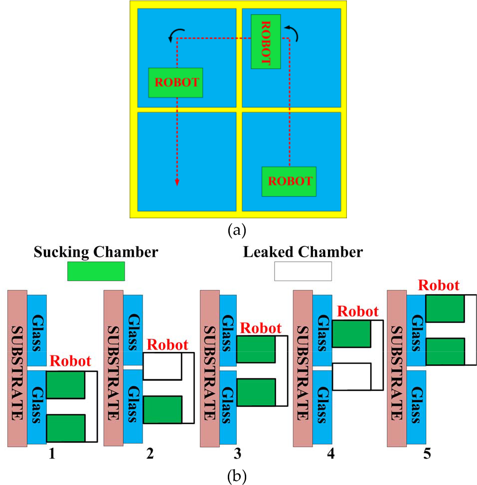
Operation trace (a) climbing trajectory (b) a robot is crossing groove with two suction chambers
3.2. Chamber shape
Apart from the number, shape of the chamber also influences the climbing performance. In general, the chamber of a negative pressure generator should cover a sealing area as large as possible to generate larger adsorption force. Meanwhile, the chamber weight should also be lightened in order to reduce the structure weight, because under given adsorption force, the fewer the structural weight, the greater operation load.
So far, most climbing robots of the negative pressure adsorption are either in round or square shape. With given circumstance, the former can cover a larger area (namely a larger adsorption force) than other shapes. However, its irregular shape also brings difficulties for layout of the electromechanical components. Figure 4 illustrates some robots with protuberant parts. In practice, the protuberant parts are easy to be damaged.

In addition, round chambers also lead to serious volume waste in the multi-chamber design. Figure 5(a) presents examples of such structures, in which the red shapes are the sealing chambers, and the green zone represents left space of the robot. With the chamber number increases from 2 to 5, the space efficiencies are about 50%, 43%, 17%, 13% respectively. Obviously, the larger the green zone, the heavier structure weight. In another word, low space efficiency of the multi-chamber structure neutralizes advantages of the round shape chamber. In contrast, an even number of square shapes are much easier to formulate a larger square almost without any space waste (Figure 5).

Layout of multi-chamber structure (a) round shapes (b) square shapes
Figure 6 is schematic view of a two-chamber robots consisted of round or square shape chambers, and the chambers are divided by a gap for groove-crossing. Assuming 1 is the minimum radius of a round chamber which can provide just enough adsorption force, then the side length of the chamber is:

Layout of square chambers in multi-chamber structure

In which a is side length of the square chamber which can generate the equal adsorption force. With two chambers divided by e, space efficiency of the two round chambers is:
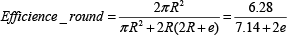
On the other side, the corresponding efficiency of the square chambers is:

To compare Eq.2 and Eq.3, the range of e is determined by the following formula:

Obviously the actual e is a positive value, therefore two square chambers are bound to have better space efficiency than two round shapes. In other word, two square chambers can be fixed by a smaller chassis (namely lighter structure weight), and they are also easier for layout of the other components. In short, square shape is relatively more optimal for the multi-chamber structure, and detailed design of the robot is based on square-shape chambers.
3.3. Negative pressure generator
The fan and the fan motor of the negative pressure generator is selected based on operational experience of the previous prototypes. The fan of 87mm diameter (Figure 7(a)) is designed for vacuum dust, and tt is driven by a high-speed brushless motor served in air-models (Figure 7(b)).

Components of negative generator (a) the fan (b) the brushless motor (c) the rubber ring (left) and PFTE film (right)
The sealing of the suction chamber is guaranteed by a soft rubber ring (Figure 7(c) left) which is used to be a tube of children bicycle. To reduce the friction force between the sealing ring and the climbing surface, a PTFE (Polytetrafluoroethylene) film (Figure 7(c) right) is wrapped around the rubber rings. All components above are off-the-shelves of civil products, and they guarantees low-cost of the robot. Previous experiments show that when the suction area is about 0.5m2, the maximum pressure difference reaches 4Kpa at least.
The pressure difference results in large stress of the chamber structure. Thus, the chamber must be solid enough or it may be crushed. Some robots use extra small wheels to support the chamber [3], but this design reduces the pressure which should have been supported by the driving wheels (lower the driving force, i.e.). For this reason, the pressure difference should be withstood by the chamber structure.
The first design of the negative pressure chamber is a unitary structure made by Polyoxymethylene (namely POM). Compared to other engineering plastics like Nylon or ABS, POM has relatively larger strength(70Mpa). In addition, some crossing ribs are also designed to enhance the strength as Figure 8(a) demonstrated. On the chassis, two chambers are separated by 50mm for grooves crossing. In spite of this, POM chamber is incompetent to withstand the pressure difference, and the pressed parts are forced to be thickened. For this reason, the overall weight reaches 5.8kg.

Two designs of the sealing chamber (a) unitary structure (b) pressure bracket and sealing chamber
The revised design divides the unitary structure into two components (Figure 8(d)). The first part is two airtight POM boxes which generate negative pressure. While the stress caused by the pressure difference is supported by the second component, namely “pressure bracket” made from duralumin (2A12).
The bracket connects the airtight boxes by screws, and it also plays a role of the robot chassis to fix other electromechanical parts, including the turban fans and the driving motors, et al. By supported by the 2A12 bracket, thickness the airtight boxes is largely thinned. Because the airtight boxes are large in volume, the weight reduction is larger than the weight of the 2A12 bracket. In this way, the new structure is lighter but more solid than the unilateral structure. Optimization of the 2A12 bracket based on FEA method further benefits for the weight reduction. After rounds of analysis with ANSYS Workbench, the weight of the revised prototype reduced to 4.5kg, and Figure 9(a) and 9(b) are stress and deformation of the final 2A12 structure.
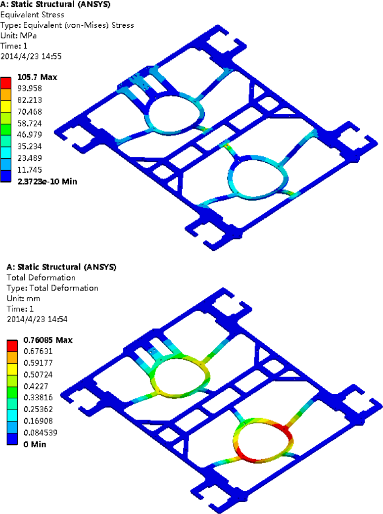
Finite element analysis of the pressure bracket (a) stress (b) deformation
4. Adsorption Analysis
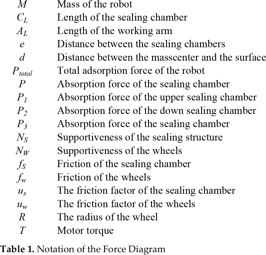
For reliable and stable operation on glass curtains, it is necessary to analyze the adsorption conditions of the robot. In order to simplify following calculation, all deformation of the components is ignored, and other related variables are listed in Table 1.
Notation of the Force Diagram
4.1. Adsorption on the plane glass
Figure 10 is the force diagram of both chambers sucking on a plane, and it represents critical situation under which the robot just keeps adsorption.

Sucking on a glass plane (a) both of the chambers are sealing (b) free body diagram
Related balance equations are listed in Eq.1:

In Eq.1, k is a supportiveness distribution factor between the wheels and the sealing rings. The factor generally fits an empirical formula:

Moreover, k is a constant for the robot, because P total changes marginally, or the climbing reliability cannot be guaranteed. Previous experiments show that k is about 0.28. The first three equations of Eq.1 relates to the resistance of the upward movement which determines the adsorption force:

Where M=4.5kg, μ w =0.1, μ S =0.8, therefore the least adsorption force for the upward movement is:

On the other side, the last equation of Eq.1 shows that the robot must withstand a overturning moment generated by the weight. By simplifying Eq.1, the adsorption force of the each chamber must satisfy Eq.5:

In Eq.5, C L =180mm, e=50mm, d is about 30mm, and the minimum adsorption force for anti-overturning is about 4.48N. Note that the adsorption force needed for the upward movement (40.2N) is much larger than the anti-overturning (4.48N), and previous tests show that each of the sucking chamber can generated about 200N. Therefore, the totall adsorption force (two sucking chambers) is far enough for the climbing operation.
4.2. Adsorption during the groove –crossing
When crossing the grooves, the robot must generate the adsorption force only by the upper or the lower chamber (Figure 11(a)), which leads to different force conditions. At the beginning of the crossing, the upper chamber is invalid as Figure 11 (b) illustrated. In this case, the balance equations are listed in Eq.6:

Vertical groove-crossing (a) two phases (b) free body diagram of the phase 1 (c) free body diagram of the phase 2

Similar to Eq.1, P 1 in Eq.6 also has different values for the upward movent and the anti-overturning:

Thus, the adsorption force of 200N is also sufficient for phase 1.
In phase 2, the adsorption force of the upper chamber (Figure 11(c)) satisfies Eq.8 when the lower chamber is crossing grooves:

Then the adsorption force of the lower chamber is obtained:

When the robot is crossing grooves horizontally (Figure 12(a)), symmetrical structure of the robot enables the free body diagram (Figure 12(b)) to represent both phases. The corresponding force equations are presented in Eq.10:

Horizontal groove-crossing (a) two phases (b) free body diagram of horizontal crossing
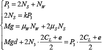
The adsorption force of each chamber satisfies Eq.11:
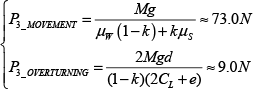
All anaysis above indicates that the adhesion force during the grooves-crossing requires at least 119.8N, while each of the chamber can provide about 200N of the sucing force. For this reason, the adhesion force of the chamber is generally enough for the climbing operation.
5. Selection of the driving motor
The upward movement also requires sufficient driving force. During the groove crossing, each of the two motors meet Eq.12:

Where μ W =0.8, P total =200N and R=0.03m. By substituting these data into Eq.12, the minimum driving torque is determined in Eq.13:

Finally two Faulhaber 3242-012CR motors are chosen as the driving motors. With a 66:1 gear box, each of the motors can provide a torque as high as 2.1Nm. Besides, the rotation speed (79rad/s) enables the robot to move at a speed determined in the following equation:

Because friction of the transmission system is not considered, real speed of the robot is slightly slower.
6. Inspection Manipulator
The inspection principle of the glass curtain is developed by China Building Science Academy (CBSA). During the inspection, a tapping force is needed to measure the frequency of the plate glass weighing about 70-80kg. Figure13 shows that the operation is conducted by beating the glass continuously which needs a working arm to fix the detection device.

Inspection process of glass plates
So far, operation arm is not a typical payload for climbing robots. In [18], B. Bridges introduces an agile arm with 6 DOF on a climbing robot for non-destructive test (NDT). Another inspiring design is the manipulator of CROMSCI which is a circular-shape arm [7], although it is relatively complex for our robots. In fact, a tail of the climbing robot is competent to fix the sensors, because the inspection can be implemented by simply beating glasses that the robot has passed by. Moreover, the tail can also reduce overturn moment of the robot. For these reasons, the working arm is fixed on bottom position of the robot, and the length (600mm) is long enough for the glass sample (2m in length, 1m in width, Figure 14(a)). In addition, the arm is made by carbon fiber rods to reduce the weight.
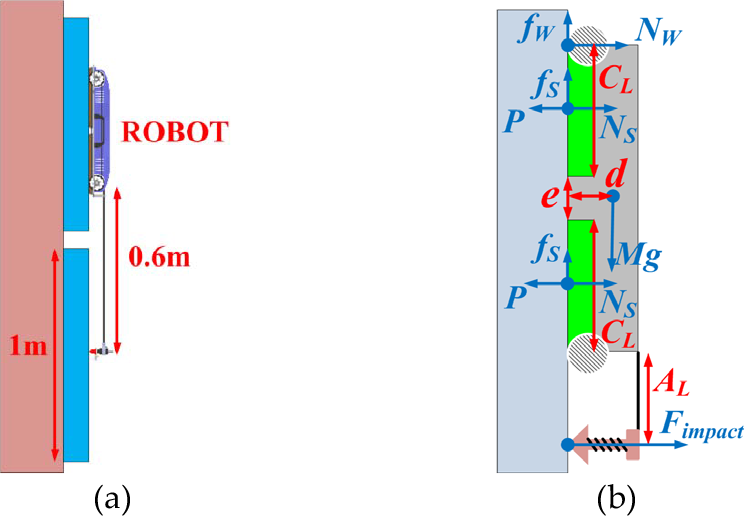
Body diagram of glass inspection (a) working arm (b) free body diagram of glass inspection
During the measurement, an excessive tapping force may harm the adsorption reliability, because direction of the tapping force opposites to the adsorption force, which means that the actual adsorption force is lowered.
The maximum tapping force must be determined for the operation safety. As Figure14 (b) demonstrated, body diagram of the tapping operation shows analytical relationship between F impact and other variables:
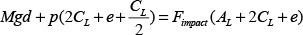
Where A L =0.6m, and the maximum tapping force is calculated in Eq.14:
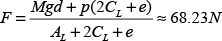
In fact, the tapping force generated by the electro-magnet is only about 10~15N which is far less than 68N. Thus, the inspection operation will not harm the adsorption.
7. Control system
Although the robot is cabled, the control system is still a wireless system to reduce diameter of the cable. In this way, both the weight and the cost of the robot can be largely reduced [19].
The human-PC interface is programmed with Lab-Windows (Figure 15). The interface enables the robot operator to control the driving motors, the negative pressure generator and the electro-magnet.

Control system (a) Human-PC interface (b) control diagram
Figure 15(b) is diagram of the control system based on a DSP TMS320F281 microchip. The control signals are sent to the robot by a wireless module (Figure16 (a)) which can choose working frequency on 315-915MHz. Receiving the control signals, the control PCB powers the driving motors through H bridges and MOSFETs, and adjusts the motor speed with corresponding encoders. For inspection of the glass curtains, the PCB uses a relay (Figure 16(b)) to control the electro-magnet which will beat the glasses with the hammer. The vibration is measured by the accelerator, and the data will be processed with a data acquisition card (DAQ). Moreover, control of the fan motors is through electric governors (Figure 16(c)) which receive PWM signals from the PCB. In addition, Figure 16(d) presents the pressure sensor (MPX5010) measuring the negative pressure. The measuring range of the sensor is 10Kpa which is far enough for the robot.
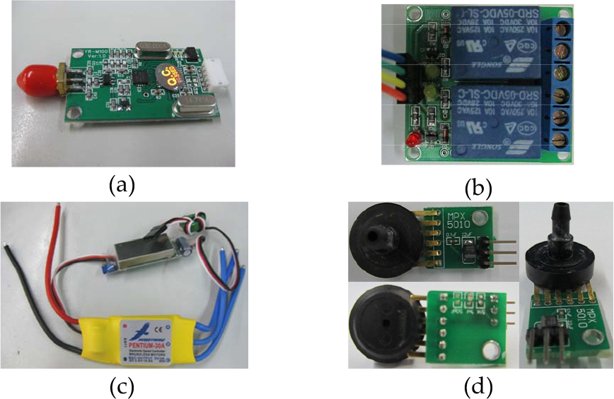
Control components(a) wireless module (b) relay (c) electric governor (d) pressure sensor
8. Experiments
Figure 17 presents two generations of the prototype. In Figure 17(a), the robot body is a unitary structure which has been proved to be relatively heavy. Then it is modified by the pressure bracket and the sealing chambers as Figure 17 (b) demonstrated.

Robot prototype (a) the first prototype with unitary structure (b) modified robot
Figure 18(a) records the robot climbing on different surfaces, including a whitewash wall, a PVC and a wooden door, as well as aluminum sheets outside buildings. These experiments illustrate that the robot is competent for operation on varied building surfaces. Groove-crossing is the priority of experiments. Firstly, the robot moves upward on the aluminum sheets which are divided by 20mm grooves as Figure 18(b) demonstrated, and the grooves are successfully crossed as expected. Then the robot is tested to climb over 30mm grooves vertically (Figure 19). The experiment circumstance is real glass curtains which can fully test the operation performance, and Figure 19(a) demonstrate the crossing process. In Figure 19(b), the robot also moves along a slant path which valids the horizontal climbing performance indirectly.

Climbing experiment (a) climbing on different surface (b) crossing of 20mm groove

Groove-crossing experiment (30mm) (a)vertical crossing (b) horizontal crossing
Inspection experiment is also conducted on the glass curtain (Figure 20(a)). In Figure 20(b), the mechanical arm is knocking a glass plate, and signals of corresponding vibration response are gathered by the accelerator in order to analyze service condition of the glass walls.

Glass inspection (a)Climbing to inspection position (b) beating glass
All experiments above illustrate that the robot not only can freely climb on the glass walls and conduct inspection operations.
Other performances of the robot are briefly listed in Table II.
General Performance

9. Conclusion and future work
This paper presents a negative pressure adsorption robot used for glass inspection. The operation path is considered firstly to determine the minimum number of the chambers for groove-crossing. Then the two squared chambers are determined as the basic structure for the weight reduction. In case of crushed by atmosphere, the POM-made chambers are designed as a unitary structure strengthened by some crossing ribs. In spite of this, insufficient strength of POM leads to the thickened chambers which increase of the overall weight. This problem is settled by redesigned the pressure structure as separate components, including two air-tight POM chambers keeping the negative pressure and a duralumin-made bracket withstanding the pressure difference. The structure is optimized by FEA method, and the robot weight is reduced from 5.8kg to 4.5kg.
For the reliable operation of vertical or horizontal groove-crossing, the statics models of different climbing situations are analyzed which enables to determine the minimum adsorption forces. In addition, the torque for driving the robot is also calculated in order to select the driving motors. Apart from the analysis above, design of the working arm and the control system are also introduced. The fixed arm is actually a tail of the robot, which can neutralize negative influence of the tapping force on the adsorption reliability. While the control system is wireless based on off-shelve products, although the robot is cabled. The wireless system not only is low cost and reliable, but also can reduce the cable diameter and the robot weight.
The robot has been tested in various experiments, including adsorption on surface of different materials, the groove-crossing climbing and glass inspection operation. Particularly, the robot successfully vertically crosses grooves of 20mm in width, and also climbs over 30mm groove in slant. These experiments fully verify theoretical analysis about the adsorption.
Future works mainly focus on two tasks:
Enhancing the robot mobility. So far, the robot can move upward at 0.2m/s, but the speed is not enough for inspeciton on higher skyscrapers. This problem will be ameliorated by further reduction of the robot weight.
Improving the robot detectivity. At present, the robot equips an accelerator for glass inspection. In future the robot will use more sensors, including micro-camera, impulse radar and other nondestructive sensors which enable the robot to inspect other surface material except for glasses.
Footnotes
10. Acknowledgement
The research of this paper is supported by China Building Science Academy (CBSA) both in terms of non-destructive inspection technology and sufficient funding support.