
Abstract
This paper introduces an innovative wall-climbing robot. The robot consists of two single-body negative pressure adsorption robots which could dock together as a mother-robot or separate into two independent child-robots. The child-robots connect with each other through a docking mechanism which can not only lock solidly and unlock smoothly but which can also adjust the relative position of the two child-robots. This design guarantees that while in dock mode the mother robot will be able to cross some barriers which are impossible to surmount for a single-body wall-climbing robot, while in separate mode the child-robots maintain agility and mobility compared to other two-body robots. In this paper, an overview of the mechanical structure of the robot is first presented and then three possible mechanisms for barrier-crossing are discussed and a reasonable one is selected. An analysis of the initial docking condition of the selected design is also given which provides the basis for the experiments and research for the future.
1. Introduction
Negative pressure adsorption supplies adsorption force by ejecting air out from the suction chamber with a high speed turbo fan. Due to its relative advantages of a simple structure, strong adsorption and great adaptability on different surfaces, negative pressure adsorption has been studied and put into practice widely compared to other suction types, such as magnetic suction, vortex vacuum suction and a variety of bionic suctions.
So far, robots using negative pressure adsorption have mainly been introduced through two designs: a single-body or a binary-body structure (namely, to connect two single-body robots with a specific mechanism). A single-body robot is relatively simple and compact, and many such systems have been used in practice, such as the BigFootI robot [1] for bridge detection. In spite of this, the main problem with single-body robots is that they can only work on a plain surface, because grooves or obstacles on the surface may seriously damage the sealing of the suction chamber and cause the robot to fall down. In contrast, binary-body robots exhibit better obstacle-crossing and surface transit performance, such as the City-Climber series robot [2] which has more than 4kg ground adsorption power and over 4.2kg surface adsorption force. However, the mobility and agility of binary-body robots are generally worse than single-body robot due to their larger body.
Based on research on advantages and disadvantages of robots cited above, this paper proposes an innovative design which has the mobility of single-body robot but which can also cross obstacles like a binary-body robot. The robot consists of two single modules, each of which can work separately; when meeting obstacles, the two modules connect with each other automatically to form a binary-body robot. After crossing the obstacle, the docking mechanism separates and the two modules are independent again, as shown in Fig. 1.

Docking wall-climbing robot.
The negative pressure generator.
The paper is mainly structured as follows: the overview of the robot structure is given initially and then, in the second part, three possible docking systems are discussed with regard to obstacle performance, proceeding with an analysis of the factors influencing initial docking conditions. The final section is the conclusion.
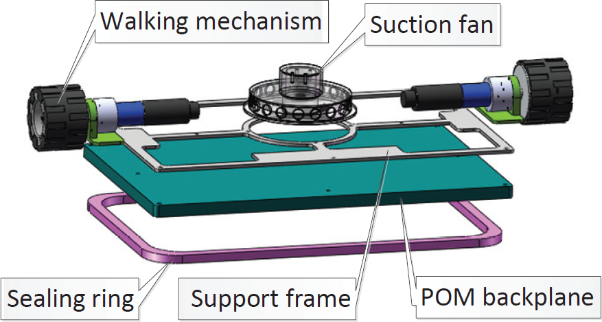
2. Structure Overview
2.1 The negative pressure generator design
The design of the single-body adsorption module concentrates on the negative pressure generator. By ejecting air from the seal chamber, the air pressure inside the seal chamber is much lower than the outside pressure, which generates a negative pressure and presses the robot onto the surface by atmospheric pressure. Therefore, the performance of the negative generator greatly influences the wall-climbing robot.
The negative pressure generator usually includes a brushless motor, a centrifugal fan and a seal chamber. Based on previous research, the rotation speed of a brushless motor driving the centrifugal fan should be within the range of 7000rpm∼30000rpm. A motor speed which is too low may affect absorption by failing to exhaust enough air, while a speed which is too high would also weaken absorption performance because it requires a larger current, which means that batteries would be larger and heavier, thus increasing the system weight.
On the other hand, the diameter of the centrifugal fan is also important because the centrifugal force of a small fan is limited, while too large a fan would increase the size and the weight of the robot. After long term experiments, a centrifuge fan with a 110mm diameter was selected which had been used on the preceding generations of climbing robots. The overall weight of the motor and the fan together was only about 45g and the output power could reach 150W under 12V.
In order to reduce the robot weight as much as possible, the sealing chamber is made of POM. To avoid deformation caused by atmospheric pressure, the chamber is supported with an aluminium alloy framework which connects the chamber with screws. This framework might not only increase the chamber's rigidity but also make it easier to mount other parts. A U-shaped groove for fixing the seal ring is mounted on the lower side of chamber board. To maintain balance between the sealing property and the necessary flexibility, a soft rubber ring is introduced as the sealing ring following experiments on two previous generations of climbing robots. In addition, the sealing ring is also wrapped with a PTFE film which greatly reduces the friction between the seal ring and the surface.
2.2 The walking mechanism
Because the single-body modules can separate and work independently mainly on a plain surface and because obstacle performance is realized by the docking mode, a 2-wheeled driving system could guarantee enough mobility for the module. On each side of the module, a DC geared-motor connects and drives a wheel. Unlike other 2-wheeled robots, the single-body module does not need a third point to withstand the counter-torque of the driving motors because the chamber (i.e., the module) is supported by the sealing ring. This design simplifies the module structure and reduces the weight as much as possible, helping to reduce the possibility of the overturning or falling of the robot on the surface.
3. Discussion of the Obstacle Performance of the Docking Mechanisms
In docking mode, the two single modules need to cross obstacles. In order to do so, the docking mechanism should not only connect solidly but also adjust the relative positions of the two modules. Therefore, obstacle-crossing performance is a priority of a docking system design.
During obstacle-crossing, the change of the relative position of the two modules always requires a large torque of servo-motors. A good design, therefore, should keep the torque as low as possible because a more powerful motor usually means too much weight. Meanwhile, and on the other side, the overturning torque caused by the change of the module's position may also weaken the absorption effect; equally, the design of the docking system should also pay sufficient attention on the overturning torque. Subject to these premises, three possible docking mechanisms are discussed and the required torque of the servo-motor in each mechanism is also deduced. Based on the analysis, a relatively suitable design is selected.
Option A: The lower module is lifted by a servo-motor fixed on the rotating joint (O) in the midst of two modules. Considering that the rotation speed will be quite low, all accelerations are ignored and the process can be analysed as a statics problem.
Eq. 1 determines the geometrical condition in Fig. 3:
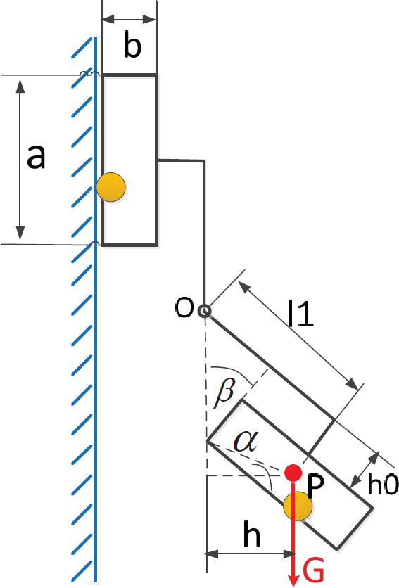
Static analysis of option one.

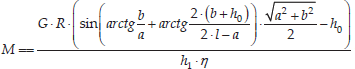
To support the rotation of the lower module, the least output torque of the servo-motor is given in Eq. 2:

Where
The swing of the lower module requires the servo-motor to output a high torque and mounting the servo-motor and the related driving system in the midst of the modules may significantly increase the complexity and reduce reliability of the whole system.
Option B: in this design, the position of the lower module is also adjusted by a rotation joint, the main difference being that the rotation joint is at the root of the connecting rod while the related driving system is fixed on the upper module, as Fig. 4 illustrates.

Static analysis of option two.
The geometrical condition is:

By solving Eq. 4, we get:

On the other side:
By substituting Eq. 5 into Eq. 6:

The torque balance equation for O is given in Eq. 8:

If the radius of the pitch circle of the rack and pinion is R:

Substitute Eq. 8 into Eq. 9 such that the output torque M is deduced in Eq. 10
Option B improves the structural design when compared to Option A since it removes the complicated joint structure and its driving system to the upper module. However, it also has to swing the lower module by a very large angle in order to cross obstacles. It means that both the output torque of the servo-motor and the overturning torque of the whole system are still quite large.
Option C: Option C changes the position of the lower module, not by swinging it as with Options A and B, but by translation (Fig. 5) driven by a screw. The main advantage of this design is that the mass centre of the lower module can be shifted by the least distance, which can significantly reduce the overturning torque. The required torque of the servo-motor is given in Eq. 11:


Static analysis of option one.

No matter what the change in the variables, the required torque M of the servo-motor for Options A (Eq.2) and B (Eq.10) will be larger than that of Option C (Eq.11), which means that Option C can use a relatively smaller and lighter servo-motor, thereby helping to reduce weight. In addition, in Option C the moving distance of the centre of gravity of the lower module is far less than with Options A and B and it greatly reduces the possibility of overturning during the obstacle-crossing process. For these reasons, Option C is ultimately selected and all of the detailed designs are based on Option C.
4. Design of the Docking Mechanism and Analysis of the Initial Docking Conditions
4.1 Design of the docking mechanism
Apart for adjusting the relative position of the modules, the main task for the docking mechanism is to ensure solid docking between the two modules, which in turn requires a simple structure with light weight and a high fault tolerance. Based on the discussion in Part 3, an innovative docking system is designed and the docking process is illustrated in Fig. 6.

The docking process.
The docking mechanism includes an active part and a passive part. The active part is mounted on the upper module and can move vertically according to Option C. Meanwhile, the passive part is a trapezoid-shaped frame fixed on the lower module. At the beginning of the docking process, the upper module should maintain a position as vertical as possible and down the active docking part to the bottom point; next, the lower module should approach the docking range. After the positions of the modules satisfy the docking condition, the active part (i.e., the cross-obstacle mechanism) should move up until it touches the trapezoidal frame on the passive part. Afterwards, the lower module should power off its turbo fan and it should slide to a corresponding position under gravity. During this process, the trapezoidal frame should stick on two hooks on the active part. To prevent the upper module from coming loose, a servo-motor is designed in order to drive two separation rods on the active part so as to lock the trapezoidal frame.
The separating process simple follows the opposite procedure.
4.2 Analysis of the initial docking conditions
By using a trapezoidal frame, the docking mechanism processes much of the fault tolerance for docking. However, the docking positions of the modules are by no means unlimited. In other words, a successful docking still requires that the modules stay within the right range.
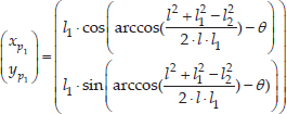
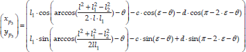
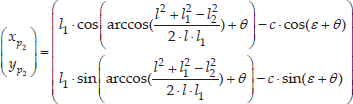
As Fig. 7 illustrates, the point O1 marks the origin of the coordinate system, in which: M is (-b, h1), N is (b, h1) and θ represents the inclination angle of the trapezoidal bottom; ε is structure angle of the trapezoidal frame; l is the trapezoid base length; d represents the top side length (P2P3); c is the hypotenuse length of the frame; and the length of O1P1 and O1P4 are l1 and l2 respectively.
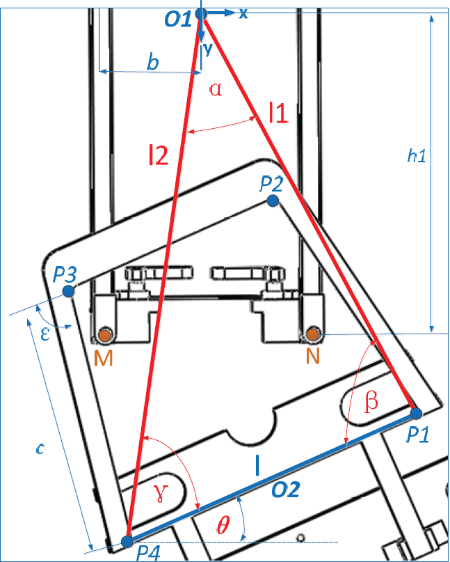
Initial docking condition.
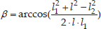
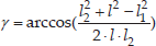
Based on geometrical condition in Fig. 7, three angles of O1P4P1 can be calculated in Eqs. 12–14:

On the other side, the coordinates P1, P2, P3 and P4 are deduced in the following four situations according to the different coordinates of the marked points P1 and P4 during the docking processing:
1. If the abscissa of P1 is greater than the abscissa of O1 and if the P1 ordinate is also greater than the P4 ordinate, the coordinates of P1 and P4 can be expressed in Eqs.15 and 16 respectively:

According to the geometrical condition and Eqs.15 and 16, the coordinate of P2 is deduced in Eq. 17.

The coordinate of P3 (Eq.18) could be deduced from the coordinate of P2:
2. If the abscissa of P1 is greater than the abscissa of O1 and if the P1 ordinate is smaller than the P4 ordinate, the coordinates of P1 and P4 can be expressed in Eqs.19 and 20 respectively:


With Eq. 20 and the geometry condition, the coordinate of P2 could be acquired in Eq. 21:
Moreover, based on Eq. 21, P3 could be deduced in Eq. 22:

3. If the abscissa of P1 is smaller than the abscissa of O1 and if the P1 ordinate is smaller than the P4 ordinate, the coordinates of P1 and P4 are Eqs.23 and 24:


The coordinate of P2 can be deduced by the coordinate of P1 from Eq. 24, which is Eq. 25:

And the coordinate of P3 is calculated by Eq. 26:

4. If the abscissa of P1 is smaller than the abscissa of O1 and if the P1 ordinate is greater than the P4 ordinate, it certainly does not meet the initial docking conditions.
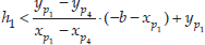
The docking condition is that the points M and N should be within the range determined by P1, P2, P3 and P4 of the trapezoidal frame. Because the coordinates of M and N are (-b,h1) and (b,h1) respectively, the straight line P1P2 could be determined by Eq. 27:

When M and N point are located on the left side of the straight line P1P2, the docking requirements are Eq. 28 and Eq. 29:


Similarly, when the points M and N are located on the lower side of the straight line P2P3, the docking condition should satisfy Eq. 30 and Eq. 31:


When points M and N are located on the right side of the straight line P3P4, the docking conditions are Eq. 32 and Eq. 33:


When points M and N are located on the upper side of the straight line P1P4, the docking requirements are Eqs.34 and 35:


In summary, the initial docking conditions are eligible when the coordinates of P1, P2, P3 and P4 satisfy Eqs.36–39: ForP1 and P2:
ForP2 and P3:


For P3 and P4:

For P1 and P4:
5. Conclusion
This paper introduces an innovative wall-climbing robot which consists of two single modules. Based on the discussion of the obstacle performance of three possible designs, a reasonable docking mechanism is selected and its details are presented. The factors affecting docking performance are also deduced and analysed, which provides a ground for determining the initial docking conditions in order to provide a basis for automatic docking control.