
Abstract
Year after year recovery clinics worldwide report significant numbers of lower limb bearing joint disabilities. An effective method for the speedy rehabilitation of patients with such afflictions is Continuous Passive Motion (CPM), drawing upon a range of specific equipment.
This paper presents an innovative constructive solution for such orthopaedic rehabilitation equipment, designed to ensure a swift reintegration of patients at as low a cost as possible. The absolute novelty consists in the utilization of the linear pneumatic muscle as actuator of the orthopaedic rehabilitation equipment, thus achieving a light and highly compliant construction that satisfies safety requirements related to man-machine interaction. Pneumatic muscles are bio-inspired actuation systems characterized by a passive variable compliant behaviour. This property, deployed in rehabilitation systems, enables the development of human friendly devices, which are comfortable for the patients, and capable of safe interaction.
This paper presents the constructive schematic of the orthopaedic rehabilitation equipment, the structure of the actuation and positioning system, and several of its functional characteristics.
1. Introduction
Disabilities caused by posttraumatic afflictions of lower limb bearing joints are known for their high incidence, namely approximately 55% of all patients admitted to medical recovery clinics [1]. This calls for the deployment of specific recovery equipment that takes over part of the work of kinetic therapists. This paper presents the construction and functional characteristics of a piece of equipment developed for the rapid recovery of patients by passive motion, the novelty consisting in its actuation by means of pneumatic muscles.
Motion therapy is generally accepted as a rehabilitation method, if a consequence of an accident or surgical intervention whereby the patient's locomotor system is affected. Therapy based on devices generating continuous passive motion is used in order to restore mobility and improve the residual motion abilities of the patient.
Continuous passive motion (CPM) is an optimum instrument within the therapeutic arsenal of rehabilitation professionals. Correct application of continuous passive motion for rehabilitation purposes requires certain background information: The patient's degree of suffering, the accurate diagnosis of the patient's condition based on muscle and joint analysis, as well as the morphopathological state of the structures to be mobilized. The main control parameters of passive mobilization are the applied force, conducted stroke, velocity of displacement, acceleration, duration and frequency of motion, all of which need to be adapted to the clinical state of the patient and the set target. This entails equipment for passive mobilization that allows adjustment within a certain range of all mentioned parameters.
Lower limb joint rehabilitation equipment currently available on the marketplace has inconveniently rigid structures, displaying a deficiency in self-adaptability to the patient's state of mobility. For this reason the current electromechanical actuation system needs to be replaced by another capable of ensuring adaptability, conformity and safety. An adequate actuator for a rehabilitation device needs to provide physically adjustable compliance and damping, must facilitate energy storage and release at certain given times, and has to ensure soft contact with the patient, similar to the behaviour of human muscles.
The main requirement for modern medical rehabilitation equipment is compliant behaviour, adjustable to patient suffering, even if at the cost of lower positioning accuracy or speed. Compliant behaviour can be active or passive. While active compliance is specific to rigid drives and is obtained by means of software, passive compliance entails the elastic elements included by the structure of the actuator. Passive compliance is characterized, among other features, by unlimited resilience to impacts and a more “natural” behaviour, thus rendering it attractive for medical recovery [2].
The passive compliance of an actuator can be constant (its modification being achievable only by replacing the elastic element), or can be variable, which ensures a permanent adaptability to a given situation. At present several actuators with passive variable compliance are known, characterized by energy efficiency and robustness, safe operation, and biomimetics, consequently including characteristics copied from biological systems. Pneumatic muscles and actuators with variable passive compliance have such biomimetic behaviour, characterized by the property that their apparent output stiffness, and thus the stiffness of the actuated joint, can be changed independently of the actuator output position.
Pneumatic muscles are designed for generating either a rotation motion (rotary elastic chambers) or a translation motion (linear pneumatic muscles). Figure 1 presents two examples of rehabilitation equipment of the knee and ankle, respectively, actuated by rotary elastic chambers [3]. Such equipment developed by the Friedrich Wilhelm Bessel Institute (FWBI) of Bremen, Germany, is compact, economic and easy to manipulate, some of their main characteristics including:

Rehabilitation equipment for knee and ankle actuated by rotary pneumatic muscles
An assistance controller that generates a force only to assist the patient in cases of insufficient muscle effort;
Assistance behaviour achievable without costly force sensors.
The pneumatic muscles analysed in this paper, manufactured by Festo, Germany, are artificial contracting actuators similar to linear motors actuated with compressed air [4]. Actuation by such devices is based on controlled deformation, the length of the achieved stroke being strictly linked to the feeding pressure (Figure 2).

Operation of a pneumatic muscle and static correlation between force, pressure and contraction of the FESTO-MAS fluidic muscle
The pneumatic muscle is a system including a contracting membrane that operates similarly to the human muscle, in that it ensures displacement by modifying its form when being fed a certain pressure. Consisting of an aramid (synthetic) fibre-reinforced elastomeric tube, the pneumatic muscle contracts rapidly when fed compressed air and generates a traction force. As the compressed air is introduced into the muscle, the traction force along its longitudinal axis causes it to shorten in proportion with the increase of the pressure. By contraction muscle length is reduced by up to 20% of its initial value in no-load state [5]. The pneumatic muscle generates its maximum force immediately upon initiation of the contraction, while at the end of the stroke the force is zero. According to [6], the force developed by a pneumatic muscle is calculated by equation (1):

where K p is an experimentally-determined constant depending on muscle stiffness, and L min is its length at a given pressure p.
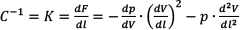
The artificial muscle models roughly the functioning of human muscle fibres and has a number of beneficial characteristics such as shock absorbing capacity and shock resistance, low weight, reduced dimensions and low mass per power unity, stick-slip free operation, elasticity (spring-like behaviour) due to air compressibility on one hand and variation of force with displacement on the other. Compliance is directly related to air compressibility, and consequently pneumatic muscle behaviour can be influenced by adjusting the control pressure. The magnitude of the compliance can be calculated starting from the expression of the force developed by a pneumatic muscle when subjected to a pressure p. In this case muscle volume increases by dV, corresponding to the modification in length dl, and the force is [7], [8]:

Compliance C, the inverse of stiffness K can be computed by equation (3):
Further on, an innovative constructive solution is presented for rehabilitation equipment for lower limb bearing joints (hip, knee, ankle), endowed with a pneumatic muscle-based actuation system. The paper is structured as follows: section two presents the kinematic diagram and the construction of the rehabilitation equipment, section three describes the structure of the actuation system and section four presents certain functional characteristics of the equipment. The paper concludes with section five including the main conclusions and outlining future directions of research.
2. Construction of the Orthopaedic Rehabilitation Equipment
Studies conducted on the motion limits of lower limbs revealed the amplitudes of the rotation angles to be achieved by the bearing joints (Figure 3):

Motion amplitudes of the lower limb joints
hip: Δϕ1 ≈ 30º;
knee: Δϕ2 ≈ 60º;
ankle: Δϕ3 ≈ 60º
The presented rehabilitation equipment was dimensioned based on these.
The angular velocity is set for the joints of the lower limb depending on the phase of rehabilitation: Slow motion is deployed in the primary phase, of restoring post-traumatic functionality of the affected joints, while a more rapid motion is specific for the advanced phase of rehabilitation aimed at building and improving the tonus of the lower limb muscles. The recommended range for angular velocities is of 30 to 150 º/min [9]. The rhythm of motion can be simple, pendular, two or four tact, with holding times at the ends of the stroke. The duration of one motion is of about 15-30 seconds, while the end-of-stroke holding time is of 5-15 seconds. A typical CPM session takes about ten minutes, its duration being adapted to the patient's pain threshold. CPM rehabilitation sessions should be repeated two to three times a day.
Figure 4 shows the kinematic diagrams underlying the construction of the rehabilitation equipment, namely a bar mechanism including four rotation and one translation joints. The first schematic refers to rehabilitation of hip and knee, and the second one to rehabilitation of the ankle.

Kinematic diagrams of the rehabilitation equipment
Thus, in the first schematic the targeted joints are hip (O) and knee (A), while the second one focuses on the ankle joint (B). Depending on the joint to undergo rehabilitation, the equipment requires certain adjustments:
in the first case joint B is blocked, the angle of bars AB and BD being constant during the entire motion;
in the second case joint A is fixed, while joint B is mobile.
The entire bar system is set into motion by translation element D, driven by a pneumatic muscle. Deployment of the pneumatic muscle as actuator solves certain main requirements of rehabilitation equipment. Thus the price of a muscle is significantly lower than that of an actuation system made up of an electric motor and a screw-nut mechanism, hence a lower-cost final product. Also utilization of a pneumatic muscle eliminates end-of-stroke shocks, due to one of the most attractive aspects of pneumatic actuation – compliance – meaning favourable answer to commands.
A prototype of the lower limb rehabilitation equipment was developed based on the kinematic diagrams presented above. Figure 5 shows two views of this, in different stages of the motion [9]. The patient uses the equipment while lying on a bed. The system can be used for either left or right leg, due to its axially symmetrical construction.

Prototype of the rehabilitation equipment
An important requirement satisfied by the rehabilitation equipment is that of low weight, as well as easy handling and transport to and by patients. This is due to the utilization of light materials, in particular aluminium, from which most components are made.
An important characteristic of this equipment is its adaptability to various dimensions of patients' lower limbs (children, adults). In this respect the joints of the mechanism can be brought closer together or distanced by simply adjusting the length of the bars.
3. Structure of the Actuation System
The linear motions of the equipment are generated by a pneumatic muscle that displaces a slide (rotational and translational element D) along a distance up to 300mm. This stroke is required for simultaneously satisfying the initial conditions imposed for the maximum amplitudes of the bearing joint rotation angles.
The construction of the mechanism includes a Festo pneumatic muscle of 20mm diameter and an initial length of 750mm. The maximum relative contraction of the muscle, as specified by the manufacturer, is 20% of its relaxed length (in this case a contraction of 150mm). Consequently a multiplying mechanism with a mobile pulley had to be included between muscle and slide, which amplifies the stroke of the slide to the required value (Figure 6). While the evident benefit of the pulley system is the doubling of the slide stroke, its disadvantage is reducing the force exerted by the slide to half of the force generated by the pneumatic muscle.

Slide stroke amplification system
As known, the force generated by a pneumatic muscle depends on its relative contraction and diminishes as the stroke increases. A force transducer was used for measurements, in order to determine the capacity of the selected muscle to develop a sufficiently great force at the slide. Thus for a 150mm stroke of the muscle the force generated and subsequently reduced via the pulley system was of 260 N, which is more than enough to mobilize a disabled lower limb. It needs be pointed out that this measured value of the force exceeds the one indicated in the manufacturer's technical specifications. Upon entering into the dedicated software supplied by the manufacturer of the pneumatic muscle, MuscleSIM, the concrete input data (20mm pneumatic muscle diameter, 750mm pneumatic muscle length, 150mm desired stroke and 6 bar feeding pressure), the programme displays the theoretical force provided by the muscle as being 338.2 N. The studied equipment includes a system of pulleys meant to double the length of the stroke; implicitly the force generated by the muscle will be halved. Thus, theoretically, the value of the force generated by the system should be 169.1 N. However, in our experiments, a significantly greater force of 260 N was measured. It can be asserted therefore that the muscle is capable of higher performance than specified by the manufacturer.
A particularity of the schematic of Figure 6 is that, upon cutting compressed air pressure, the slide is unable to return to zero position on its own. Once no more compressed air is fed to the pneumatic muscle, its free end returns to its initial, resting position. This, however, does not entail the returning of the slide to return to its initial (withdrawn) position, as there is no force to cause this. For this reason the returning of the slide is ensured by including a repositioning spring in the construction of the equipment.
A further role of this spring is to compensate the hysteresis of the pneumatic muscle. Occurrence of hysteresis is explained by the friction between the exterior wall of the muscle elastic tube and its enveloping tissue. Hysteresis represents a major disadvantage in the deployment of pneumatic muscles, particularly in applications that require high accuracy positioning.
Hysteresis behaviour of the utilized pneumatic actuator was determined by measuring its contractions Δl (Δl = l initial - l final ) when subjected to a range of external loads, while being fed pressure in a sequence from 0 to 6 bars.
The graph in Figure 7 illustrates the variation of contraction during muscle inflation and deflation, respectively, in the case of loading the muscle by a mass m = 20 kg, which is approximately the mass of a leg.

Evolution of muscle contraction versus feeding pressure
The pneumatic muscle is inflated with pressures from 0 to 6 bars, followed by its dilatation from 6 bars to 0. It can be noticed that the values measured during deflation are greater than those during inflation.
For both inflation and deflation the generated contractions were measured for each integer value of the pressure. As illustrated in the graph, the greatest difference between muscle contractions is of 20.86mm and occurs for feeding compressed air at a pressure of 2 bars.
The maximum contraction of the tested pneumatic muscle is of 186.44mm. Hence its relative contraction is:
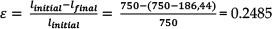
that is 24.85%. This value deviates from a contraction of only 20% indicated in the technical specifications provided by the manufacturer. The actual capacity of the muscle to shorten beyond the values provided by its technical specifications enables the rehabilitation equipment to carry out greater strokes than those initially imposed, thus amplifying the possible variation range of lower limb joint rotation angles.
Control of a pneumatic muscle is difficult because of the non-linearity of its physical parameters. Over time various control strategies were developed for pneumatic muscle actuated equipment, and a number of research reports on its positioning systems can be found in literature. For example a Kohonen-type neural network was used for positioning the end-effector of a robot with a precision of up to 1 cm [10]. Papers [11…15] argue in favour of controlling pneumatic muscle-actuated manipulators by PID, of fuzzy PD + I learning control, robust control, feedback linearization control and variable structure control algorithms.
The rehabilitation equipment proposed in this paper is based on the utilization of a proportional directional control valve, allowing the development of a rapid, accurate, and cost-effective control system, adjustable to the various external loads it is subjected to.
Figure 8 illustrates control of the pneumatic muscle and the structure of the positioning system.
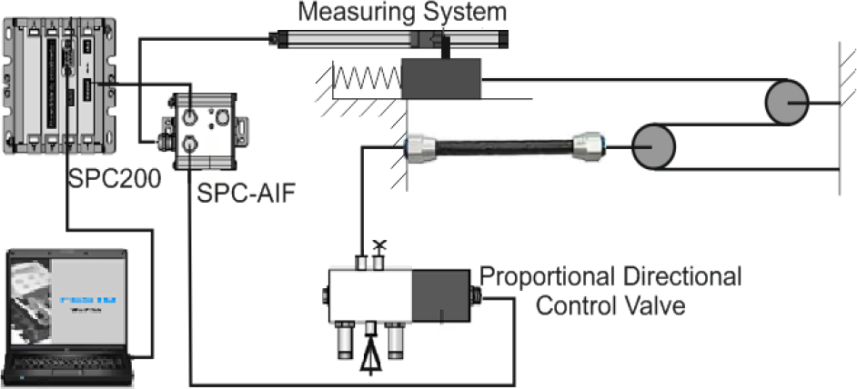
Structure of the positioning system
The positioning system used in this application ensures flexibility, speed, and a low cost and sufficient precision for concrete operational requirements. Such systems are recommended for all linear pneumatic motors required to stop in more than two positions, and have stays of different durations.
The system includes:
the pneumatic muscle actuated by a proportional directional control valve. An MPYE (Festo) proportional valve with a position-controlled spool was selected. This transforms an analogue input signal into a corresponding opening cross-section at the valve outputs. In combination with an external position controller and displacement encoder, a precise pneumatic positioning system can be created. The proportional directional control valve operates up to a pressure of 10 bar and allows an airflow of up to 750 l/min;
a resistive position transducer attached to the slide;
an SPC 200 controller for programming and saving the working positions, the types of motion and their sequence; programming, operation and diagnosis of the controller are achieved by WinPISA software. WinPISA is a software for planning, operating, programming and trouble shooting of pneumatic actuations including an SPC 200 type controller. Its main functions are the simultaneous management of several linear pneumatic motors, their operation and online diagnosis, as well as programming of positioning systems according to DIN 66025 norms; This software further allows plotting of graphs describing the evolution versus time of displacement, speed and acceleration of the mobile elements.
The capacity of an SPC 200 controller allows storing of up to 100 different rehabilitation programmes, that include a maximum total of 2000 NC programme lines. The compilers for the NC programmes used by an SPC 200 are based on DIN 66025 norm;
electronic elements for the transmission of information from the transducer to the controller and of the commands issued by the controller to the proportional valve (electronic elements included by the SPC-AIF interface).
The measured quantity is a displacement related to the origin of the frame of reference and is provided by the position transducer. The system allows the programming of one or more cycles of rehabilitation exercises, depending on the degree of mobility of each individual patient.
4. Functional characteristics of the orthopaedic rehabilitation equipment
Analysis of the operational behaviour of the bearing joint rehabilitation equipment was achieved by means of a programme written in WinPISA that commands a sequence of different displacements of the stroke. The WinPISA programme causes a stepwise motion of the slide by a 50mm increment, the speed being set to its maximum possible value.
Starting from the kinematic diagram of the equipment, the correspondence between the rotation angles of the knee and the hip joints and the distance travelled by the slide could be established, considering that this is the only motion parameter that can be entered into programmes written in WinPISA. Table 1 shows these correspondences.
Correspondence between the displacement of the slide and the rotation angles of the hip and knee joints
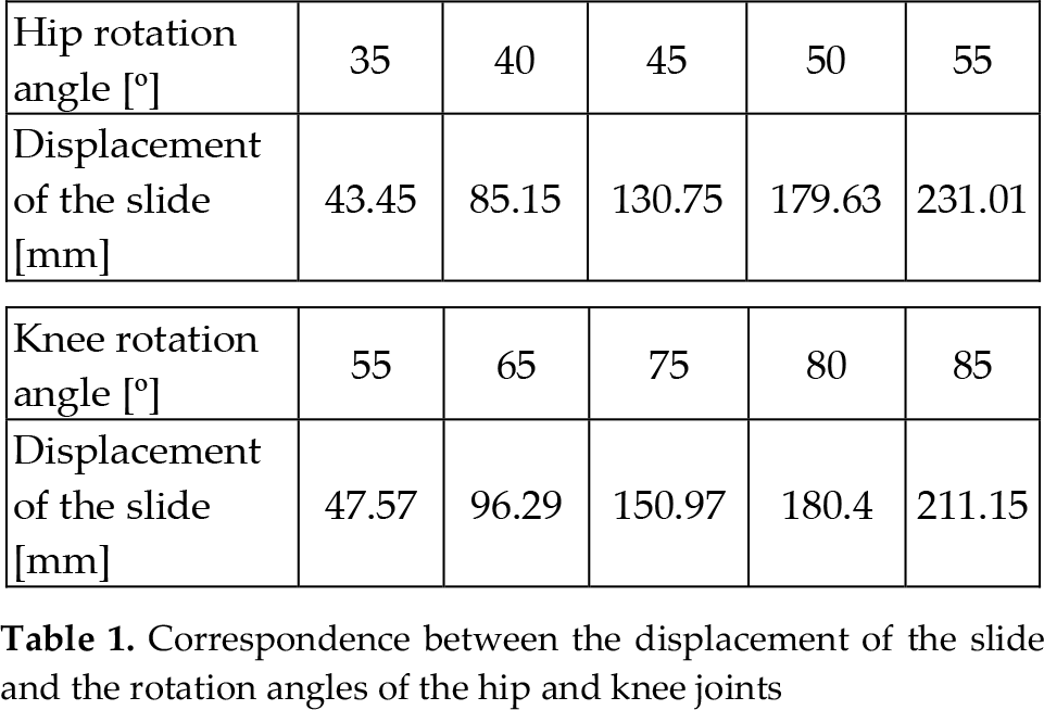
Figure 9 shows the graph of slide displacement versus time. For this cycle of motion WinPISA also plots the evolution of slide speed versus time and of speed versus displacement. Figures 10 and 11 show these dependencies.

Slide displacement versus time

Slide speed versus time

Slide speed versus displacement
Figure 12 illustrates the variation of acceleration versus time.

Evolution of acceleration versus time
Analysis of the graphs yields the following conclusions:
for this cycle of motions an adequate positioning precision of the slide is obtained; a deviation of a few tens of millimetres does not affect the efficiency of medical recovery;
a slight delay of command execution by the slide was observed;
the durations of stays in the commanded positions are greater than programmed (1 s) and increase with the slide moving further away from its initial position, what also does not affect the quality of the rehabilitation exercise;
as the slide moves away from the origin, the slopes describing the real motion become smaller, indicating a diminishing speed;
with the displacement of the slide also increased shifting of the times required for achieving the commanded positions is observed. This is caused by the decrease in slide speed, which deviates from its programmed value. The explanation consists in the fact that as the muscle contracts and moves the slide away from origin, its force decreases. At the same time the force of the repositioning spring grows, hence also the resistance to motion. This causes a diminishing of the speed as the slide moves away from the origin;
the change of direction of motion is achieved shock-free, proving the compliant nature of the pneumatic muscle;
the maximum velocity of the slide is of 0.2 m/s, which translates into angular velocities of the joints up to 20º/s. These values are significantly greater than those needed for rehabilitation exercises, but the programme allows for obtaining smaller values of the velocity.
the acceleration of the motion ranges from −5 m/s2 to +6 m/s2, respectively, except for certain initial impulses at the beginning of the motion.
As regards the service life of the deployed pneumatic muscle, this has not been the subject of the conducted tests. However, considering the manufacturer's specifications, the expected service life of the muscle ranges from 100,000 to 10 million switching cycles for typical applications.
The safety of the system is controlled by both hardware (limit switches) and software if the motion velocity is increased over the limits. The most important aspect, however, is related to patient safety and concerns avoiding the occurrence of pain during rehabilitation exercises. This is the main reason for that pneumatic muscles are used, as air compressibility renders their behaviour inherently compliant.
5. Conclusion
This paper presents pneumatic muscle-actuated rehabilitation equipment for lower limb bearing joints. The mechanical structure of the equipment is described, as well as the structures of the actuation and positioning systems together with their operational characteristics. Special focus is placed on describing the utilized pneumatic muscle, highlighting its special characteristics that render it optimum for medical equipment developed for patient rehabilitation by continuous passive motion.
In addition to the functional characteristics described in section four of the paper, the economic aspect entailed by such rehabilitation equipment is also significant. The cost of the described constructive solution actuated by a linear pneumatic muscle is estimated at 60-70% of the equipment currently available on the marketplace, actuated by electric motors.
The equipment proposed in this paper lends itself, in addition to recovery of lower limb joints (hip, knee, ankle) via continuous passive motion also to utilization by athletes, for training leg musculature or analysing muscle performance.
Future objectives related to this rehabilitation equipment envisage:
development of physical therapy training programmes to form a library of treatment procedures;
further development of the control architecture;
development of software to demonstrate the use of the system as a motion and power analysis system.
As a general conclusion to the research reported in this paper it can be asserted that the results obtained prove the capability and high performance of the proposed rehabilitation system, as well as the eligibility of pneumatic muscles as adequate actuators of medical recovery systems.
Footnotes
6. Acknowledgments
This paper is supported by the Sectoral Operational Programme Human Resources Development (SOP HRD), financed from the European Social Fund and by the Romanian Government under the contract number POSDRU 134378.