
Abstract
This article proposes a novel, innovative, soft gripper system developed for the manipulation of objects of unknown or unspecified shape and consistence. This could be achieved by the utilization of a linear pneumatic muscle benefitting from an inherently compliant behaviour. A gripper system of this type does not require the presence of sensors or complex controllers, as it is the mechanical system itself that provides the required adaptive behaviour. The compliance of the system is ensured by the variations of the air pressure fed to the pneumatic muscle, monitored and controlled in a closed loop by means of proportional pressure regulator.
Introduction
Robotic systems whose design and control strategies are aimed at ensuring the capacity of achieving safe physical human–robot interactions (soft robots) have been studied and developed increasingly over the last years. Parts of these robots consist only of rigid components, in which case their structure includes sensing and control capabilities allowing to operate more safely in human environments. 1 Another category of soft robots includes those conceived according to the principles of biomimetics, systems made from soft and/or smart materials that relate to the functional morphology of living organisms. The soft nature allows the robots to adapt to their surroundings, to perform different and even autonomous tasks and to mimic the motion and function of biological systems, such as human muscles. 2
Lately, soft robot applications have known continuous developments because of the need for addressing issues that cannot be solved by classical robots manufactured from rigid components. The concept of soft robotics entails the development of soft structures, deformable, elastic or not, capable of functioning in uncertain and dynamic task environments, like grasping objects of unknown or unspecified shape and consistence or close machine–human interactions. 3,4
An essential component of a robot is its gripper system. Designing a new gripper system needs to take into account the desired functional characteristics like the developed force, stiffness, compliance, dexterity and number of degrees of freedom. Based on these requirements, current industrial applications use simple and reliable grippers that develop large forces and have a significantly rigid structure, while more complex solutions like mechanical hands are proposed for finer applications that require high compliance and dexterity. Conceiving a solution that brings together both simple gripping and high compliance is however not excluded and has not been explored.
The idea of a gripper system attached to a robot originates from the human hand that fulfils numerous functions, the most important one being gripping, meaning the action of grasping, of seizing with the help of fingers, of tweezers and so on. Starting from the human model, in the field of robotics, gripping entails achieving contact between the final effector element of the robot (the gripper) and the body to be manipulated. Grippers are those components of robotic systems that facilitate the temporary contact with the manipulated object, ensuring its position and orientation while a specific work task is being carried out.
Like soft robots, soft grippers too have known continued development over the last decade, due to the requirement for versatile robots that interact within a variety of environments. 5 –7
Soft gripper systems are made from components of low stiffness, which enables an inherently safe and adaptive contact with both solid and soft surfaces. Among the numerous applications of such gripper systems entailing compliant and delicate manipulation of objects are grasping irregular and/or fragile objects, 8,9 non-invasive surgical procedures, 10 automated assembly operations, 11 wearable and field robotics, 12,13 assistive devices, prostheses or artificial organs 14 and so on.
The action of gripping is achieved by developing mechanical contact forces. While in natural systems these forces are generated by muscles, in artificial grippers forces are generated by motors. Typically, the motor is linked to the gripping jaws via a mechanism consisting of rigid elements. In the case of such rigid gripping systems, a high force applied to the manipulated object can deform or even destroy it (Figure 1).

Gripping by applying an uncontrolled force.
In systems lacking either closed loop control for the achieved contact or the capacity of recognizing objects, the magnitude of the force exerted for damage-free seizing is controlled merely by the human operator.
Such undesired outcomes can be avoided by using soft fluidic actuation that ensures the adaptability of the gripper system to a concrete working situation. In this case, the adequate gripping force of a deformable object is developed by gradually increasing the pressure of a fluid that is introduced into a closed chamber. The architecture of the pressure chamber determines its deformation by a preferential direction, 15 and generates a displacement that can be an expansion or a contraction. The idea of contraction by a certain direction emerged by mimicking the behaviour of human muscles that contract in response to stimuli.
An example of soft fluidic actuator is the pneumatic artificial muscle (PAM) that has undergone multiple development since the 1950s. Well known are the McKibben muscles and those derived from these 16 –18 Grippers based on pneumatic muscles have certain advantages: they are soft and lend themselves to the manipulation of objects of various forms and weights; also, their control is uncomplicated and does not require a closed loop control for the achieved contact.
Upon analysing the current state of soft gripper systems yields the conclusion that the concept of utilizing pneumatic muscles has not been sufficiently exploited. It is in this sense that this article presents and discusses the construction and performance of a novel gripper system actuated by a pneumatic muscle type motor, a bio-inspired system similar to human and animal muscles.
The further sections of this article present the characteristics of pneumatic muscles that render them eligible for soft gripper systems, with an emphasis on a specific property of pneumatic muscles known as compliance. The requirements to be met by soft gripper systems are established, followed by the discussion of an original constructive solution of a gripper and its actuation. Further the obtained experimental results are presented with a focus on the analysis of the system’s compliant behaviour. This article continues with a case study and closes with a chapter of conclusions.
Soft gripping requirements
To date only few examples of pneumatic muscle-actuated gripper systems are known. One of these is the Power Gripper developed by Festo, Germany with a construction based on Watt linkages. 19 The idea underlying its conception was a study of the way birds use their beak to grasp objects. Another example is the one described in our previous work, 11 namely a gripper system for assembly operations. Used in both cases were pneumatic muscles manufactured by Festo, which copy by biomimetics the functioning of the human muscle fibre. Figure 2 illustrates how the human arm whose motions are achieved by biological muscles was used as a source of inspiration for the pneumatic muscle that actuates a robotic arm developed by biomimetics.

Transition from the human to the pneumatic muscle.
The main constructive element of artificial pneumatic muscles is a flexible tube made from chloroprene with a tight envelope consisting of inelastic aramid fibres displayed by a diamond pattern forming a 3D lattice. Due to this construction, once compressed air is fed to the pneumatic muscle, it behaves similarly to the human muscle, undergoing axial contraction by modification of the geometric form. As the pressure in the chloroprene tube increases, a traction force is generated along the longitudinal axis that causes the muscle to shorten proportionally to the magnitude of the internal pressure (Figure 3).

Operational principle of the pneumatic muscle.
The main properties of pneumatic muscles that recommend them for various applications are the capacity of absorbing shocks and shock resistance, small overall dimensions and small mass by unit of power, elasticity (similar behaviour to that of a spring) determined on one hand by air compressibility and on the other by the variation of force versus displacement, easy connectivity, safe deployment, capacity of developing forces of about 8–10 times greater than those generated by cylinders of similar dimensions, capacity of functioning at various air pressure, absence of stick-slip, the muscle develops a smooth and natural motion as well as swift contraction and so on.
Another important property pneumatic muscles benefit from is compliance, the inverse of stiffness. Under the influence of exterior forces, a compliant system allows deviations from a given position of equilibrium. As the dependence between the force developed by the pneumatic muscle and the stroke is not linear (Figure 3), it follows that its stiffness and implicitly its compliance are not constant. An adjustable compliance is obtained by varying the feed pressure of pneumatic muscles, which enables the thus actuated system to adapt to the concrete operational situation. Such a system does not require the presence of sensors or complex controllers, as the mechanical system itself is able to ensure an adequate adaptive behaviour. 8 This property of pneumatic muscles renders them eligible for soft gripping type applications.
The seizing and manipulation by robots of fragile, deformable objects generally requires gripper systems endowed with a complex of sensors. An alternative to such systems is the utilization of variable stiffness actuators, also known as adjustable compliant actuators (ACAs). A significant property of ACAs is their capacity of storing and releasing energy by means of passive elastic elements. As already stated, in such a system the presence of sensors or complex controllers is not necessary, as it is the mechanical system itself that provides the required adaptive behaviour. 11
The adaptive behaviour of a gripper system refers to its capacity of seizing objects of unknown shape and consistence without damaging them, or its capacity to adapt to constraints generated by the specific work environment (e.g. positioning the gripper relative to the gripped object). Figure 4 illustrates the required variation of a gripper system’s compliance/stiffness and of the displacement of the jaws, respectively, versus time such as to facilitate the soft gripping of fragile objects. The necessary phases for seizing and clamping the object are approaching the targeted object, initiation of contact and securing the seized object between the jaws by increasing the clamping force.

Variation versus time of jaw stroke and system compliance/stiffness.
Initially, during approaching and positioning of the jaws in relation to the targeted object, a high stiffness of the system is required, and implicitly minimum compliance. As soon as the contact between the jaws and the targeted object has been achieved, in order to avoid deformation of the object, the system’s compliance has to tend towards a maximum, while its stiffness has to be minimized. Special significance comes to the shape of the two curves that describe the variation of compliance and stiffness. The concave shape of the compliance curve shows that during the first stage of the jaw stroke, when high precision is required, the gradient of compliance increase is small, while at the end of stroke compliance increases abruptly. Once the jaw has achieved contact with the targeted object, compliance reaches its maximum values, ensuring soft, non-destructive grasping.
This article presents a constructive solution of a gripper system that meets the above described requirements, namely that is capable to continuously vary its behaviour between two limits, from soft to rigid and vice versa. The actuation element of the proposed system is a pneumatic muscle, and the required work motions are ensured via a pinion-rack mechanical transmission. A motor of adjustable compliance like the pneumatic muscle can adapt its operational behaviour between two limits, ranging from rigid – for high accuracy positioning – to compliant, when the main desideratum is not precision, but safety of the motion. 20 The proposed solution respects the requirements specified in Figure 4 related to the form of the variation curves of the system compliance and rigidity, thus ensuring a soft gripping of the fragile objects.
Modelling of the gripper
The proposed gripper system is of angular type, with two mobile jaws, as illustrated in the diagram of principle in Figure 5. The assembly’s motor element is a pneumatic muscle that once fed compressed air sets into motion a double rack that interacts with two gears fixed rigidly on the supporting arms of the jaws. The contact forces developed between the jaws and the gripped object (F
2 and

where m is the module (pitch) of the gear, z is the number of teeth of the gears, R is the distance from the rotation centre of the gears to the contact point between the jaw and the object and γ is the angle of rotation of the jaws.

Operational principle of the gripper system.
The gripper system was designed starting from the following input data: mass of the object M = 0.5 kg; acceleration of the motion of the system consisting of the gripper and the object: a = 5 m/s2; gravitational acceleration: g = 9.81 m/s2; emergency stop deceleration: a S = 10 m/s2; friction coefficient: µ = 0.2; safety coefficient: S = 2.5, m = 1 mm, z = 30 teeth, R = 55 mm. Based on these data, equation (2) calculates the necessary force to be developed by each jaw such as to retain the gripped object

From equations (1) and (2), the maximum force (F 1) to be developed by the pneumatic muscle is obtained

According to this value, the adequate pneumatic muscles are of 10 mm interior diameter and 45 mm active length, namely MAS-10-45N-AA-MC-O-ER-EG (Festo). Figure 6 shows the characteristic diagram of the forces developed by this muscle. It can be noticed that in order to ensure the maximum necessary gripping force F 1 max at a working pressure of 6 bar, the stroke of the pneumatic muscle ranges from 0 to 0.5 mm. The smaller the feed pressure, the lesser the weight that can be seized will be.

Variation of the force versus the stroke and charging pressure.
The structural and block diagrams of the gripper system are presented in Figure 7.

Structural and block diagrams of the gripper system.
The gripper system is an aggregate consisting of two parallel-connected linkages (M I and M II) with L = 3 external links. The mechanism includes three components (one rack and two gears), all of rank 1, meaning that they allow the forming of only one kinematic couple. Considering mechanisms M I and M II isolated, the degree of mobility of the mechanical system is

As the number of couplings L C = 1, the degree of mobility of the system is

meaning that the studied gripper is described by an independent input velocity (v
1) and a dependent input force (F
1). The remaining exterior motions (ω
2 and
The friction forces in the system were taken into consideration in determining the transmission function of forces and torques. Thus a 0.97 efficiency of the pinion-rack mechanism was considered for calculations (η
12
,

Homogenous diagram associated to the gripper system.
This entails determining the following quantities:
The matrix associated to the aggregate

The product operator by row

The sum operator by column Σ C

The global efficiency is

Based on the magnitude of the global efficiency, the transmission function for forces and torques can be written

where from
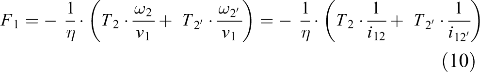
The technical data of the pinion-rack mechanism are known, that is, the transmission ratios are i
12 =

Based on this equation and knowing the maximum force F 2 that can be applied for the seizing of an object without damaging it, the magnitude of the actuation force F 1 can be determined, and consequently the feed pressure of the pneumatic muscle.
Figure 9 shows the constructive model of the gripper system, and Figure 10 features its actuation diagram.
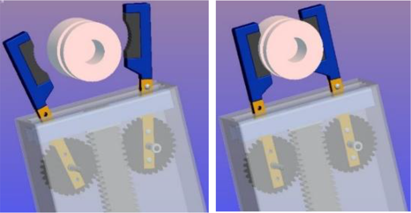
Constructive model of the soft gripper system.

Control of the soft gripper system.
The pneumatic control diagram of the muscle includes a proportional pressure regulator that receives an electric signal from either a reference module or an external potentiometer. This allows for continuous modification of the regulator’s feed pressure, causing the permanent variation of air pressure in the pneumatic muscle. This is a pressure-based control scheme where the pressure within the pneumatic muscle is measured and controlled in a closed loop. The possibility of continuously modifying the air pressure ensures the variation of the entire system’s compliance.
The functional model of the gripper system was devised with the SimMechanics module available in MATLAB R2008b.
The motion of the gripper system was induced by means of a Sine Wave block, which was selected because the motion pattern of a pneumatic muscle resembles a sinusoid. The output quantity of this block that is applied to rack 1 is of linear displacement type

where A is the amplitude of the motion, p is its pulsation and φ is the initial phase.
The application of a sine signal for a duration of 2 s causes the antagonist variation of the motion quantities of jaws 2 and 2′ (angular position, angular velocity and angular acceleration) according to the graphs in Figure 11. The limit values of these three quantities corresponding to a 9 mm displacement of the rack are: the maximum angular position is 34.37°, the maximum angular velocity is 55°/s and the maximum angular acceleration is 35°/s2.

Evolution of angular displacements, velocities and accelerations of jaw supports 2 and 2′ versus time.
Experimental results
The main purpose of the experimental study was to establish the compliant character of the entire gripper system. It is known that in order to be compliant, a system needs to display a non-linear dependency in relation to the stroke of the force developed by it. In order to verify this condition, a set-up was devised for the measurement of the force developed by one jaw (F 2) when the displacement of the rack is caused by a force F 1 (Figure 12).
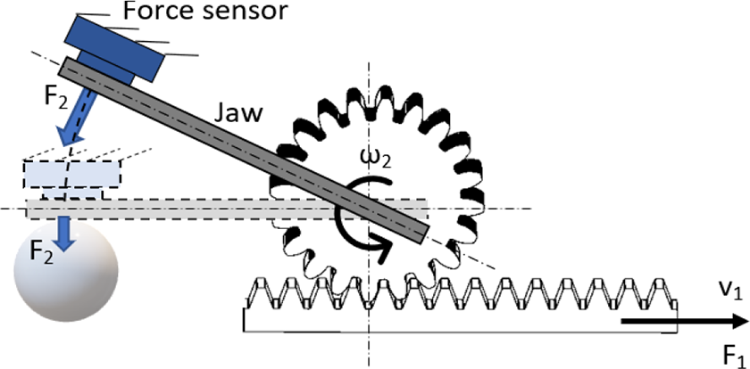
Force measurement developed by one jaw.
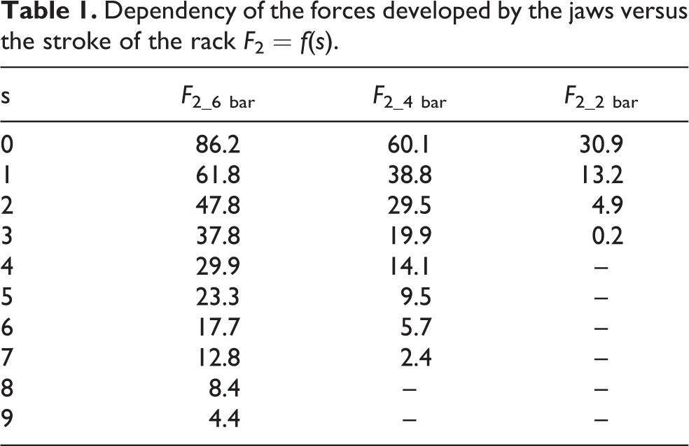
As the magnitude of force F 2 varies during the rotation of the jaw, it had to be measured in several positions, namely for every millimetre of rack displacement, corresponding to every 3.8° of the jaw’s rotation angle. Table 1 features the data collected by the conducted measurements. Figure 13 features the graph that shows the variation of force F 2 versus the stroke (s) of the rack fixed to the free end of the pneumatic muscle.
Dependency of the forces developed by the jaws versus the stroke of the rack F 2 = f(s).

Variation of the force developed by one jaw versus the stroke of the rack and pressure.
The above-mentioned experimental results confirm that the proposed gripper system is capable of working with an object that has the imposed specifications and of ensuring at each of the jaws the necessary force for retaining the gripped object (equation (2)).
The functions that best describe the evolutions of the measured forces (with a correlation coefficient r 2 > 0.99) have the form of equation (12)

with the values of coefficients a 1…5 given in Table 2.
Values of the coefficients of the polynomial regression function.
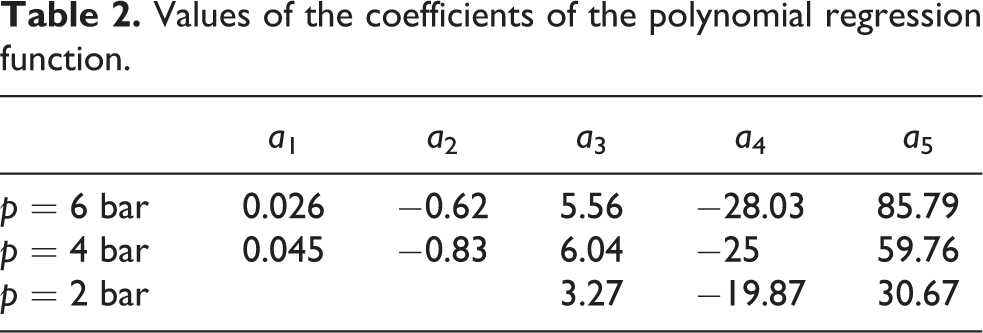
A non-linear descending evolution of the developed force is noticeable as the stroke of the rack progresses. Consequently, a variable stiffness k and a variable compliance C are obtained, expressed by equations (13) and (14)


Figures 14 and 15 present the variations of stiffness and compliance versus the stroke of the rack and the feed pressure. The two graphs confirm the hypotheses of Figure 4, namely that stiffness has a decreasing and compliance an increasing trend while the jaws of the gripper system approach the targeted object. It is important to point out that as the moment of contact and firm holding of the object draws closer, due to the approximately concave shape of the compliance curve its gradient becomes increasingly abrupt, the compliance of the gripper system thus reaching high values in a short time. This variation pattern of stiffness and compliance favours applications where the main requirement is to ensure the safe handling of the gripped object, to the detriment of positioning precision.
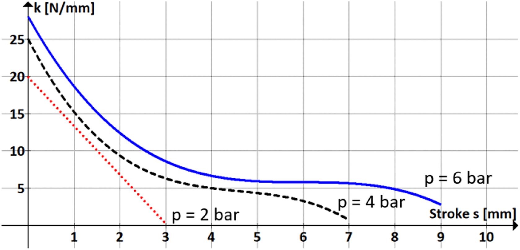
Variation of stiffness versus the stroke of the rack and air pressure.
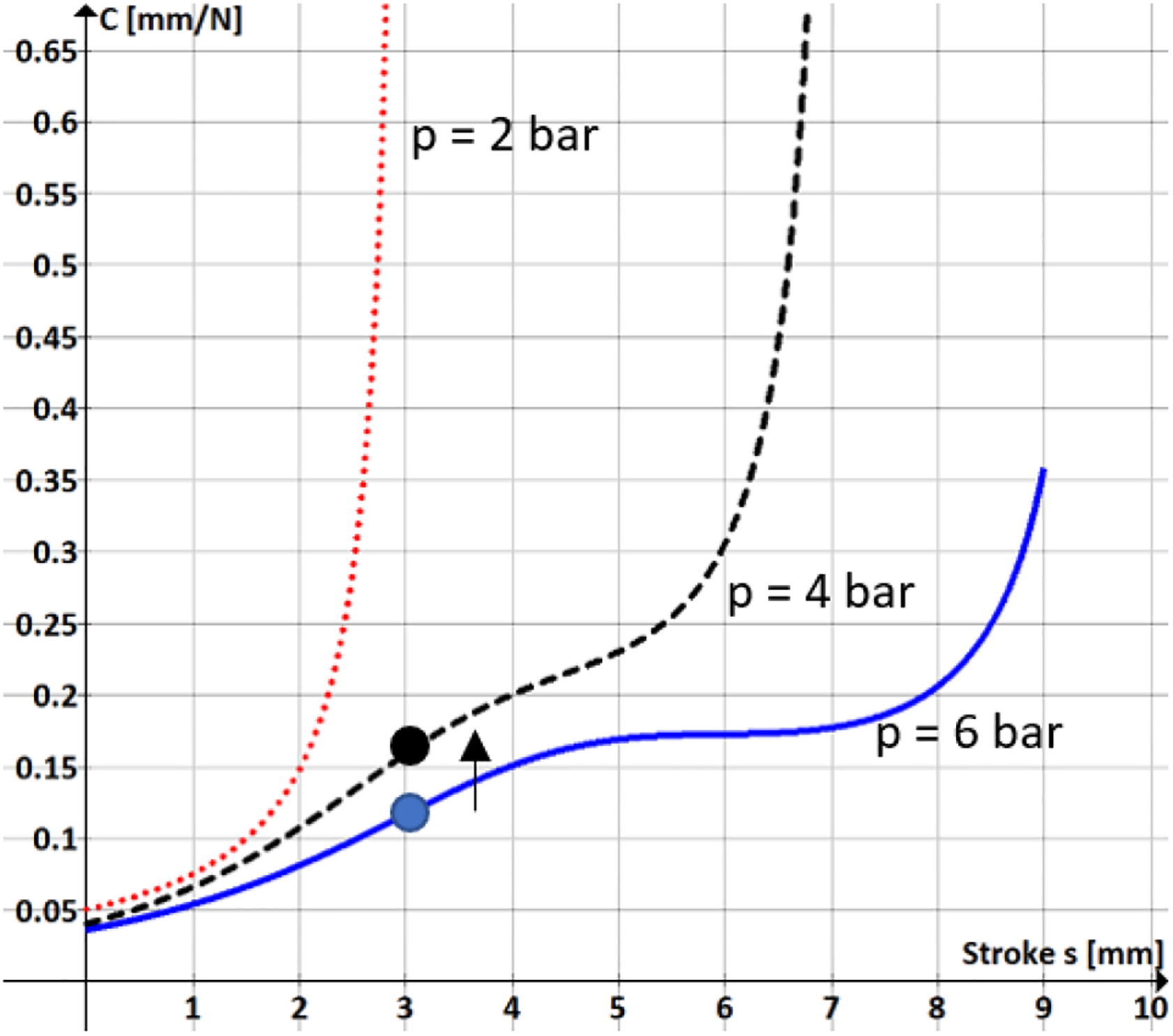
Variation of compliance versus the stroke of the rack and air pressure.
The graph in Figure 15 also shows that once the object has been touched, compliance can be adapted by the adequate adjustment of the working pressure. The example illustrated in this figure shows that for an imposed stroke of the rack of 3 mm, by lowering air pressure from 6 to 4 bar, compliance increases from 0.1163 to 0.1585 mm/N. Higher values of compliance render the gripper system more adequate for seizing delicate, fragile, easily deformable objects, the forces developed by the jaws being smaller. The possibility of adjusting compliance allows for the limitation of the contact forces to values acceptable for safe handling, without requiring any feedback.
The application discussed further on illustrates the utilization of the gripper. The gripper system has to hold a 330 ml can filled with liquid (Figure 16), with a mass of M = 0.366 kg, exterior diameter D e = 66.3 mm and wall thickness w = 0.1 mm. The can is made from aluminium with a modulus of elasticity E = 70 GPa. By applying equation (2), the necessary value of the force is obtained that allows the gripper system to retain the can: F 2 = 45.31 N; further, from equation (3) results the force that has to be developed by the pneumatic muscle: F 1 = 293 N. The contact surface between the gripper jaws and the can is AS = 10 mm2.

Deformation of the can filled with liquid.
For these input data, the radial deformation of the can wall consequently to the distributed application of force F 2 is

A firm holding of the can between the jaws of the gripper system by a constant force F 2 requires an additional displacement of the jaws by a quantity Δw, meaning the adaptation of the gripper to the actual specifics of the seized objects (the deformability of the thin walls of the can). This can be achieved due to the system’s compliance, namely due to the possibility of modifying the position of the jaws by adequately adjusting the pressure of the air. Figure 17 shows the increase of the feed pressure of the pneumatic muscle required for compensating the jaw stroke by an additional quantity Δw. For the data of this case study, an additional displacement of the jaws by 0.71 mm, namely from s = 1 to s = 1.71 mm, entails an increase of air pressure from 4.63 to 5.39 bar.

Compensation of jaw stroke by modifying pressure.
Figure 18 presents the variation of the system’s compliance with the modification of air pressure and the increase of the stroke of the jaws. An increase of compliance once with the deformation of the seized object can be noticed, for both illustrated levels of pressure.

Increase of compliance consequently to the compensation of the stroke of the jaw.
Conclusions
It is undoubtedly a challenge to conceive soft gripper systems capable of seizing objects of irregular shapes or various consistencies. This article puts forward such a system benefitting from a simple structure and reduced manufacturing costs, and with a morphology that is easily adapted to various applications. The gripper is actuated by a pneumatic muscle, an inherently compliant actuator that copies the characteristics and performances of the biological muscle. Compliance is particularly useful when it comes to the muscles of the hand, as it ensures passive adaptability to the seized object.
This article analyses the behaviour of the gripper system with regard to the forces, the stiffness and the compliance it is able to achieve. As to compliance, the essential characteristic for soft gripping, the study demonstrates that this can be adjusted by varying the pressure of the air fed to the pneumatic muscle. Pressure variation is monitored and controlled in a closed loop, by means of a proportional pressure regulator. Based on the measurements, we demonstrated that the form of the compliance variation curve is concave, as desired, as it favours applications where the main requirement is to ensure the safe handling of the gripped object. Adjustable compliance makes possible the soft gripping of the targeted object, a grip that is adaptable to the shape and consistence of the object. Easily manufactured at reasonable costs, the adjustable compliant soft gripper system put forward and discussed in this article can be successfully implemented for everyday tasks.
Footnotes
Declaration of conflicting interests
The authors declared no potential conflicts of interest with respect to the research, authorship, and/or publication of this article.
Funding
The author(s) received no financial support for the research, authorship, and/or publication of this article.