
Abstract
Bioinspired quadruped robots are among the best robot designs for field missions over the complex terrain encountered in extraterrestrial landscapes and disaster scenarios caused by natural and human-made catastrophes, such as those caused by nuclear power plant accidents and radiological emergencies. For such applications, the performance characteristics of the robots should include high mobility, adaptability to the terrain, the ability to handle a large payload and good endurance. Nature can provide inspiration for quadruped designs that are well suited for traversing complex terrain. Horse legs are an example of a structure that has evolved to exhibit good performance characteristics. In this paper, a leg design exhibiting the key features of horse legs is briefly described. This leg is an underactuated mechanism because it has two actively driven degrees of freedom (DOFs) and one passively driven DOF. In this work, two control laws intended to be use in the stan ce phase are described: a control law that considers passive mechanism dynamics and a second law that neglects these dynamics. The performance of the two control laws is experimentally evaluated and compared. The results indicate that the first control law better achieves the control goal; however, the use of the second is not completely unjustified.
1. Introduction
As society evolves, its technological requirements also evolve. In particular, modern societies require robots that can safely negotiate complex terrain for a variety of applications, such as extraterrestrial exploration or search and rescue operations in disaster scenarios caused by natural and human-made catastrophes, such as those caused by nuclear power plant accidents and radiological emergencies. In general, wheeled vehicles may not be able to negotiate these types of terrain (e.g., when there is a very complex terrain). Legged animals provide evidence that legs may be necessary for traversing complex terrain [1].
Several legged robots have been built [1, 2, 3, 4, 7, 5]; however, only a few are capable of achieving agile locomotion [8, 4]. One probable reason for this deficiency [9] is that the most common approach to building legged machines, from 19th-century wind-up toys to many of the modern legged robots, is to mimic the joint trajectories of animals.
However, this approach has become less common over the last decade, and a new generation of biologically inspired robots is emerging [1, 8, 10]. In addition to mimicking the joint angle trajectories of animals, these robots attempt to emulate the key features that distinguish the dynamic behaviour of animals. One of the main characteristics of these robots that allows them to mimic the springy tendons in animals is the use of springs and other passive elements to simplify the control of the leg and to conserve energy [10, 11]. Furthermore, control methods are being developed to take advantage of the dynamic characteristics of these systems [10, 11], where several researchers are building systems that do not require any level of control [9]. Most of these studies have been performed with the general goal of increasing energy efficiency and thus improving autonomy and endurance. However, these designs are v ery sensitive to disturbances.
In contrast, most modern robotic applications, influenced by traditional industrial robotics, use a completely different approach in which the natural dynamics of the mechanism are cancelled out to achieve the precise following of the desired trajectory.
Nature can provide inspiration for the design of legged robots that are suited for traversing complex terrain. One source of inspiration is agile quadrupeds, of which horses are among the most efficient. Horse legs have evolved to provide speed, endurance and strength superior to the legs of any other animal of equal size [12]. The adaptation of horse legs for agile performance has resulted in longer legs relative to body size than those of similar quadrupeds, resulting in a longer stride length. Horse legs are relatively lightweight and have a mass distribution that improves the leg's oscillation frequency [12]. The horse leg's kinematic structure optimizes the use of its joints for bearing loads. Endurance for locomotion results from the economy of effort achieved by the storage of elastic energy in the tendons during certain phases of the locomotion cycle. This energy is returned during the more demanding phases of the cycle.
Following these examples that nature has provided, one can anticipate the substantial advantages of controlling the motion of a bioinspired horse-like leg. However, controlling the motion of a mechanism that includes both active and passive elements, which must be synchronized and feature different inherent dynamics, is not straightforward.
Previous works on legged locomotion that combine active and passive actuation (i.e., using passive elements as actuators such as springs) can be classified as limit-cycle walkers [13, 14] and force-controlled underactuated legged robots. The former type focuses on the energy efficiency advantage of passive dynamics and uses active elements to inject the instantaneous dynamic requirements that are not provided by passive elements to maintain the robot in a limit-cycle. The latter type is more suited for complex, natural environments due to their robustness to unexpected perturbations, which is an advantage over limit-cycle walkers.
Force-based control of underactuated robots taking advantage of elastic elements has been addressed by Grizzle and his collaborators [15, 16, 17], who proposed the hybrid zero dynamics (HZD) approach, which has been shown to be robust to moderate terrain unevenness and stiffness [18]. However, rather than taking advantage of the system dynamics, the HZD approach converts the system (through virtual constraints) to a certain target model and then applies control laws that are suitable for the new model. Nevertheless, HZD has been adapted to preserve the dynamics of passive elements in the case of MABEL [15, 19], which is used to modify only a portion of the robot dynamic behaviour [15] and accommodates its behaviour to the passive element to achieve asymptotically stable behaviour.
Nonetheless, more intuitive control methods for using compliant actuation systems have been proposed [6, 20]. Whereas the hybrid zero dynamics approach relies on a detailed dynamic modelling of the robot, Pratt's virtual model control [21, 22] presents an approach that controls active elements so that they behave as passive elements. However, this method is not directly applicable to control an underactuated mechanism because it uses virtual passive elements on each joint and in task space to achieve its desired behaviour, although this work is based on Pratt's approach.
However, virtual model control requires an ideal behaviour of the active elements to reproduce the desired robot dynamics. This problem is augmented when a real passive element is inserted in series with active elements.
There are many reasons why the robotics community has studied underactuated robots. Previous studies have demonstrated that a sufficient condition for an underactuated robotic manipulator is that the number of passive joints is less than or equal to the number of active joints [23, 24], where the output controlled is the position or exerted force of the end effector (in this case the robot's foot). Control strategies have been proposed to control systems that exploit the systems' intrinsic dynamic coupling [23, 25, 26] in both the joint and task spaces. These approaches have been implemented on legged robots [27, 28]. Such strategies allow passive joints to move freely until the desired joint position is achieved; the passive joint is then blocked, allowing the other joints to move such that the overall desired position can be achieved. However, for the leg presented in this paper, such strategies cannot be directly applied because the passive joint cannot move freely due to its attached spring.
In this study, a force-based impedance control scheme [29] is implemented on a bioinspired underactuated leg prototype (fig. 1). This prototype is a planar 3-DOF leg directly driven by two series elastic actuators (SEAs), one at the hip and the other at the knee. The fetlock joint is passively driven by a spring resembling the superficial digital flexor in horses [30]. The impedance control law was motivated by the fact that animals appear to change the apparent stiffness of their legs to accommodate the terrain [31, 32]. The objective of impedance control is not to directly control position or force, but the relationship between them. This allows reducing or increasing apparent stiffness, damping or mass depending on the task. Moreover, with a single control scheme it is possible to control both position and force, although not directly. In addition, it is important to note that the control schemes studied in this work are intended to reduce impact forces when the legs hits the ground and to modify the apparent leg stiffness during the support phase.

The HADE leg prototype: conceptual design (left) and prototype (right)
This paper experimentally compares the performance of two control approaches applied to an underactuated mechanism. The goal of this comparison is to determine the extent to which it is necessary or desirable to take advantage of passive element dynamics to achieve a certain control objective. This issue is important because underactuated mechanisms complicate the controller design significantly and because underactuated mechanisms cannot follow arbitrarily defined trajectories [33], thus creating a limit to the workspace of the leg. This can be a disadvantage in the case of a legged robot because it is desirable that the leg is capable of following any particular trajectory to avoid collisions or to reach a certain foothold.
Because field robots are intended to work in unstructured environments, interaction control schemes are used in this paper. In this study, two control laws will be applied to the leg and their performance will be compared. One control law incorporates the dynamic effects of the spring, and the other law neglects these effects. The objective of this investigation is to study the effect of the spring dynamics in the performance of the leg, in terms of a desired impedance.
In this paper, the design of the HADE leg [8], which exhibits the key features of a horse leg, is briefly described in Section 2. Section 3 presents the two control laws. In Section 4, the proposed control law is experimentally validated, and the performance of the two control laws is compared. Finally, Section 5 provides the conclusions and future work.
2. The HADE Leg Design
The design of the HADE leg has been described in detail in previous publications. In this paper, a brief summary of the design is included for the sake of completeness, and the interested reader is referred to [34, 8] for a complete discussion on the leg's mechanical design.
The HADE leg was designed to try to achieve the horse leg's superior speed, endurance and strength in an artificial prototype. Five key elements affect the performance of the horse leg:
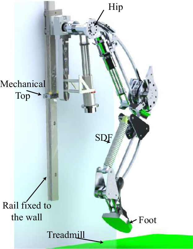
The biomimetic design of the 3-DOF planar leg, shown in Figure 2, accounts for these five elements. The leg is actuated at the hip and knee by two series elastic actuators (SEAs), and the fetlock is passively driven by a spring. The actuators represent the muscles in a horse's hip and knee, and the fetlock spring emulates the superficial digital flexor.
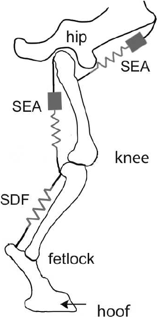
Biomimetic model of a leg for agile locomotion. The series elastic actuators are labelled as SEA, and SDF is the superficial digital flexor
SEAs were selected as the driving actuators for the leg's active joints because the SEA behaviour resembles the muscles' mechanical responses and the neuromuscular control system's behaviour [39].
The direct kinematics of the leg is described by the following equations for a 3-DOF planar manipulator (see Figure 1):


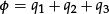
where

Graphical representation of the control objective

where,

The dynamics of the HADE leg is derived here as follows: first of all let us recall the expression of the torque for a robotic manipulator with elastic joints [?]:


where
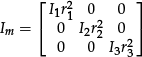
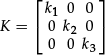
and K is a diagonal matrix containing the spring constants of each joint, i.e.,
where the expression

where

where
3. Impedance Control Strategy
This study investigates the value of incorporating the effect of a spring-driven joint in the impedance control law for an underactuated leg. We compare two control approaches. The first approach considers the leg to be fully actuated, i.e., the control law only includes the two actuated degrees of freedom, and the torques and displacements produced by the spring are treated as disturbances in the control loop. The second approach accounts for all three of the legs' DOFs and includes a feed-forward term to the two active joints to account for the torque produced by the spring. The following control objective is used for both control laws:

where
The following two control laws, each designed to achieve the control objective, are applied to the leg.
3.1. Force-based impedance control law neglecting the spring dynamics (NSD)
The first control law considers the leg to have two DOFs and treats the passive joint as a disturbance. The reference forces are given by

where
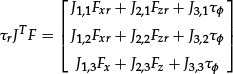
The reference torques are given by the following equation, which maps the task space forces to the joint torques:

where the subscripts indicate that

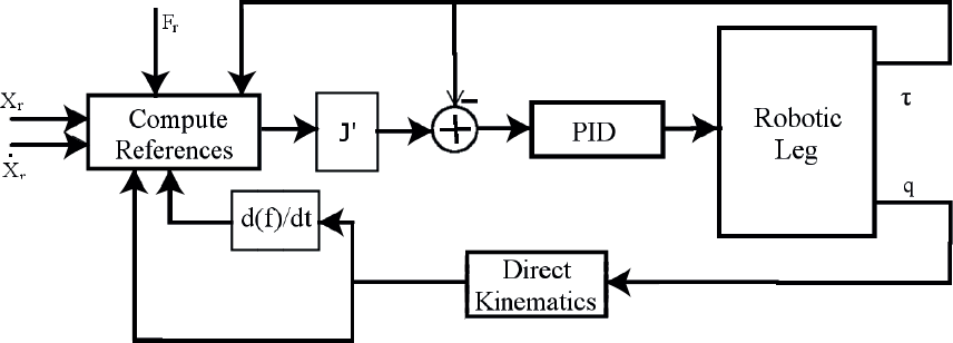
Equations (12) and (13) lead to the control scheme shown in Figure 4.

Force-based impedance control scheme in which the spring dynamics are neglected
It is important to note that the NSD controller assumes that the leg's tip is the ankle. The importance of this assumption will be discussed in detail below.
3.2. Force-based impedance control law incorporating the spring dynamics
The second control law considers the leg to have three DOFs. The control law assumes that the passively driven joint is uncontrolled; however, a feed-forward term is included in the reference forces for the active joints. Consider that:
where

thus, the reference forces are given by:

where

where the subscripts indicate that

where,

As can be observed in the above equations, the reference given to the third joint is the exerted torque
The control scheme described in this section, based on equations (17) and (19), is depicted in Figure 5.
Force-based impedance control scheme in which the spring dynamics are included
3.2.1. Applicability of the impedance control law incorporating the spring dynamics
Several important remarks should be made concerning this control law. First, assuming that the PID controller accurately tracks the reference torques, mapping the achieved torques to the task space forces yields


where
Setting
Selecting a leg configuration that causes the terms other than
We will discuss the second alternative, which requires the following set of equations to be solved:


Solving these equations defines a workspace with perfect force tracking. Figure 6 shows this workspace, which is computed by assuming that

Workspace of the control law for
Additionally, if a wider workspace is needed because the form of the steady-state error is known, the control law could be modified to include a feed-forward term to pre-compensate for this error. This approach is commonly used in the control of flexible manipulators [40].
The second important remark is that this control law is based on the implicit assumption that the flexible behaviour (in the directions of motion) of the spring during free motion can be neglected. This assumption is valid for springs that are sufficiently rigid to maintain
3.3. Discussion
Note that in the above analysis, the role of the SEAs springs was neglected because the spring constant of the actuators is 400 times larger than the higher spring constant of the spring attached to the fetlock joint. Consequently, the dynamic effects of the SEAs springs are much faster than those of the fetlock spring and can thus be safely neglected.
In addition, note that the actuators are force controlled; thus, the joint position error is not considered by the internal PID controller. However, both control laws account for the position error in task space (see equations 12 and 17), and this error is transformed into a force error, which is still corrected by the control law, as with any force-based impedance control [29].
Regarding the definition of the force and position references, this controller intends to be a lower level control for a walking robot, where the position and force references are generated in a higher level and then passed to the controller. The desired forces (
4. Experiments and Results
To test the proposed control method incorporating the spring dynamics, the control scheme (Figure 5) was implemented in the HADE leg prototype (Figure 1).
4.1. Experimental setup
Figure 7 shows the experimental setup used in this study. The leg (see Figure 1) is fixed at the hip to a rail that allows for vertical movement of the base (hip) and restricts horizontal movements. The rail is fixed to a wall and has a mechanical limit to prevent falling. Moreover, the foot is placed on the surface of a motorized treadmill to allow for horizontal displacement of the foot against the surface.
Experimental setup
Each leg actuator included encoders to measure joint position and force, and the fetlock's spring deflection was measured by a linear encoder. The control law and data acquisition were implemented with a National Instruments NI PXI-1042Q with a control loop execution time of 500 μ s.
The exerted force at the foot was computed using the measured force on each joint using the formula
4.2. Influence of the leg dynamics
Before validating the proposed control laws it is important to remark that neither of the control schemes consider the complete leg dynamics. This simplification can be done because we have corroborated both analytically (see Section 2) and experimentally that the influence of the leg dynamics is not significant in the first two joints. The experimental evaluation is the subject of this subsection.
To evaluate the influence of the leg dynamics we have conducted a series of experiments with the leg suspended (in order to eliminate the

Position controller to evaluate leg dynamics
First, to evaluate the gravitational component the leg is commanded to follow a variety of trajectories covering the whole workspace, ensuring low, constant speed and no acceleration. The observed variation of the controller error among trajectories was 3 % for the hip joint and 2 % for the knee joint. These errors are not significant enough to consider the system as dynamical.
Second, to analyse the effect of the Coriolis term (
Finally, to evaluate the influence of the inertial terms, the same trajectory used for the experiment of the Coriolis term was used, this time using a constant acceleration of value 0.5 m/
Error variation of the leg

4.3. Control law validation
In this section, we will experimentally validate the applicability of the ISD control scheme by testing its performance on the leg using two different SDF spring stiffness coefficients to demonstrate that the control law can accommodate variations in the spring stiffness. Note that the primary goal of the control law is to control the vertical leg stiffness, thus a certain error is expected in position and force both vertical and horizontal, though the vertical force error should perform better (within the applicable workspace) than the horizontal force. In the experiments, the leg was placed in an arbitrary initial position, with the foot in contact with the ground. The leg was commanded with a desired foot force pattern intended to illustrate the assumptions made in Section 3. A first spring with
Figure 9 shows the pattern of the commanded vertical foot forces for the leg (dashed line), the measured force when using

Vertical force reference (dashed line) and vertical force with an ISD controller using
Similarly, Figure 10 shows the pattern of the commanded horizontal foot forces for the leg (dashed line) and the controller response using
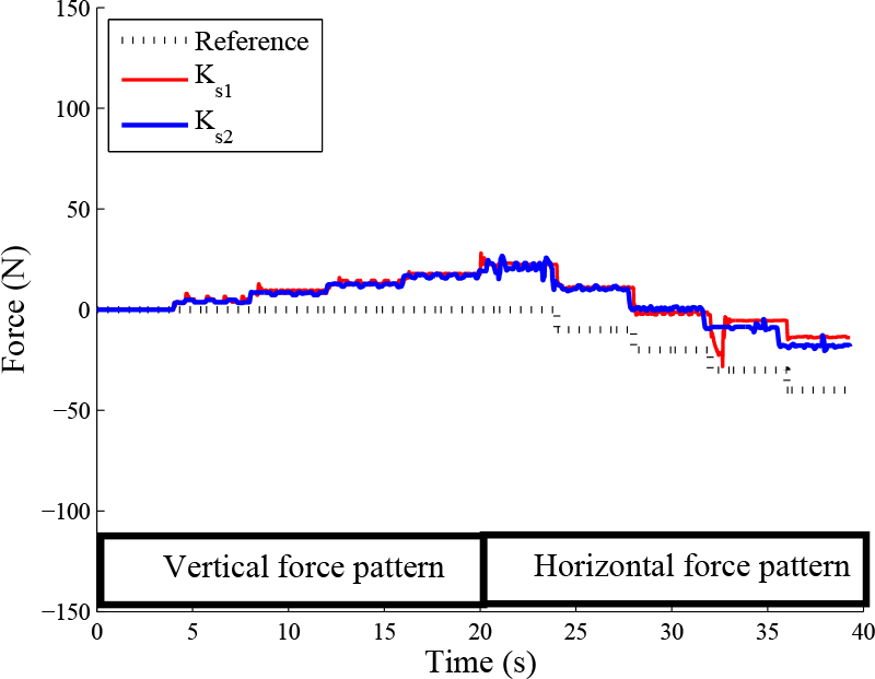
Horizontal force reference (dashed line) and vertical force with an ISD controller using
It can be seen from the figures that the tracking performance of the controller is almost the same for both springs used. The results show that the disturbances created by moving the leg in one coordinate direction produce a chattering behaviour in the other direction (i.e.,
These results show that the control law accomplishes the objective of tracking the reference force despite the changes in the spring's stiffness. When the stiffer spring was used, the impact peaks that occurred when the leg came in contact with the ground were reduced. Thus, the stiffer spring was used in the experiments to compare the two proposed control laws.
As a final comment on the experiments, note that the vertical force should be negative to maintain contact, which means that a positive force would ultimately lead to separation; however, because the foot force was not measured by a force sensor but calculated from the joint torques with the relationship
4.4. Control comparison
The objective of this section is to determine the extent to which it is necessary or desirable to take advantage of the spring dynamics to achieve a certain control objective. Here, we compare the experimental performance of the control laws described above. To accomplish this objective, two experiments were performed. In the first experiment, the leg was placed in the same initial position used for the previous experiments and a sweeping force pattern, consisting of a series of step signals from 0 N to −100 N of 1 s each, was commanded in each direction (
To produce a meaningful comparison, when computing the vertical and horizontal forces and position values for the NSD control law, the full 3-DOF kinematic model of the leg and the measured values of
Figures 11 and 12 show the average mean square error for the leg's vertical and horizontal positions, respectively, where the results obtained with the ISD and NSD controllers are shown as a solid line and dashed line, respectively. In the figures, it can be seen that as the value of K increases, the performance of each controller is fairly similar. However, for low values of K, the NSD controller presents a lower position error (with the exception of
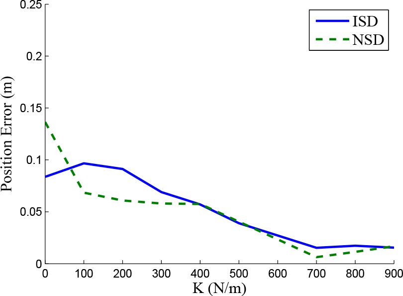
Vertical position error vs. K for the NSD (dashed line) and the ISD (solid line) control schemes

Horizontal position error vs. K for the NSD (dashed line) and the ISD (solid line) control schemes
Figures 13 and 14 show the average mean square error for the leg's vertical and horizontal forces, respectively, where the results obtained with the ISD and NSD controllers are shown as a solid line and dashed line, respectively. It is important to note that the force error shown in the figures refers to the desired foot force

Vertical force error vs. K for the NSD (dashed line) and the ISD (solid line) control schemes

Horizontal force error vs. K for the NSD (dashed line) and the ISD (solid line) control schemes
Nevertheless, the NSD controller exhibited a lower force error than the ISD controller because the PID loop rejected the spring contributions, whereas the ISD controller does not. This result indicates that in terms of the control objective (describing a desired impedance), the ISD controller outperformed the NSD controller.
It is worth noting that the leg's dynamics (gravitational and centrifugal terms) are not considered in the analysis, which makes the results dependent on the configuration. For that reason, the second experiment, performed to evaluate the controllers' performance, consisted of commanding a desired trajectory to the leg, which covers the anticipated workspace. Note that this is not the primary objective of the control law, and that the scheme is not intended to be used to position the leg in a desired location, but describe a force-position relationship when the leg is in contact with the ground. Thus the following experiments were only performed for comparison purposes. Note that the ground is located at
A square trajectory was selected as a reference because it involves decoupling the vertical and horizontal movements on the leg, which can be a serious problem when using manipulators with elastic elements [42]. Figure 15 shows the reference trajectory (dashed line) and foot trajectory with the ISD controller (thick solid line) and NSD controller (thin solid line) at a speed of 1 km/h. As shown in the figure, the behaviour of the two control approaches is very similar at low velocities. Figure 16 shows the reference trajectory (dashed line) and foot trajectory with the ISD controller (thick solid line) and NSD controller (thin solid line) at a speed of 2 km/h. In this figure, it can be seen that the trajectory-following performances of the controllers differ significantly. It is important to note that the leg makes contact with the treadmill when the foot coordinate is
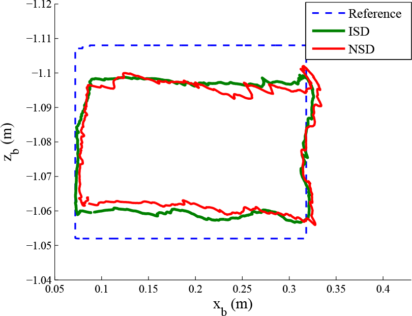
Reference trajectory (dashed line) and foot trajectory with the ISD controller (thick solid line) and NSD controller (thin solid line) at a speed of 1 km/h
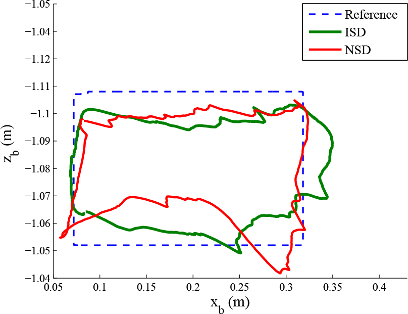
Reference trajectory (dashed line) and foot trajectory with the ISD controller (thick solid line) and NSD controller (thin solid line) at a speed of 2 km/h
As a final comment, it is important to note that at low velocities, both controllers exhibit the same performance; however, at higher velocities, which are when impact forces are important, compensating for the spring-produced torque allows the trajectory to be more closely followed. In other words, a controller that considers the elastic element on the leg performs better than one that neglects it.
5. Conclusions
This study presented an impedance control approach for a biomimetic robotic leg for agile locomotion. The leg's design is inspired by horse legs and exhibits the most important features, in the authors' opinion, of this animal model. The leg is driven by two SEAs, one at the hip joint and one at the knee joint. The fetlock is passively driven by a spring resembling the superficial digital flexor.
To control the leg motion and ground interaction, a control law was proposed based on the literature on robotic manipulators with passive joints. Two controllers were presented and described, one that neglects the spring dynamics and one that considers the spring dynamics. The workspace in which the steady-state error tends to zero was presented, and a means of extending the workspace to the full range of the leg workspace was discussed. Both proposed control laws were implemented in a real 3-DOF planar leg prototype, and experiments comparing their performance were conducted.
The results showed that both control laws achieve the expected performance in position error for an impedance control law at slow velocities. However, as the velocity increases, the control law neglecting the spring dynamics starts to fail because it does not account for the spring induced torques.
In summary, the control law incorporating spring dynamics outperforms the NSD control law. Nevertheless, the position tracking performance of the two control laws is very similar, for the majority of the impedances studied, the NSD controller exhibited a lower error in both position and force. Thus, even though the NSD controller was outperformed in terms of the impedance control objective, this controller is better suited when following position and force references alone is desired.
Footnotes
6. Acknowledgements
This work has been supported by Madrid Community through the project TECHNOFUSION (S2009/ENE-1679). Mr Juan Carlos Arevalo and Mr Manuel Cestari would like to thank the Spanish National Research Council and the Spanish Ministry of Economy and Competitiveness for funding their PhD research.