
Abstract
Underactuated robotics is an emerging research direction in the field of robotics. The control input of the underactuated robot is less than the degree of freedom of the system. It has the advantages of lightweight, low energy consumption, excellent performance, and broad development prospects. This article reviews the state of the art on underactuated robotics. On the basis of previous studies, this article takes the non-holonomic constraint equation as the entry point to classify and summarize underactuated robot and their common mechanisms. The controllability of underactuated robot is further discussed. The control flow of underactuated robot is described based on the open–closed control method. In the closed-loop control, the control method based on the fuzzy system is mainly used. Finally, the difficulties in the current research of underactuated robot are summarized, and the future research directions are prospected.
Keywords
Introduction
According to the International Federation for the Theory of Machines and Mechanisms terminology, the degree of freedom (DOF) of a mechanism is the number of independent generalized coordinates that completely defines the configuration of a system at any instant of time. By comparing the DOF and the number of actuators, mechanisms could be categorized in three types: fully actuated mechanisms, redundantly actuated mechanisms, and underactuated mechanisms. The number of actuators of the underactuated mechanism is less than its DOF. In terms of mechanism, the underactuated robot (UR) is a kind of robot with underactuated mechanism. From the perspective of control, URs refer to a class of robots with independent control input less than the DOF of the system.
Under normal circumstances, the robot has underactuated characteristics in the following situations
1
–5
: Inspired by human motion, it is used for bionic robots to achieve efficient and beautiful movements, such as gymnastics robots and so on. In order to make certain structures simple and efficient, the flexibility of the system is increased and the use of underactuated joints could greatly reduce weight and cost, such as two propeller satellites, flexible-link robots, and so on. The robot system itself has some dynamic constraints that make it a UR, such as aircrafts, underactuated stratospheric airships,
6
underactuated submarines,
7
and so on. In some emergency situations, if the drive motor fails and could not be replaced, it is practical to treat the joint at the drive motor into an underactuated joint to meet the requirements of emergency, such as surface ships and so on. More complex low-order nonlinear systems have been artificially created to study the control of high-order UR systems, such as two-stage inverted pendulum (IP), bat system, rotating pendulum, and so on.
Although UR is more complex than full-drive robot, UR has a number of advantages, such as energy savings, material savings, space savings, and so on. In some specific cases, if there is precise drive control, UR could achieve higher efficiency and better flexibility even with a lot of DOF (e.g. biped walking robots, robots, etc.). Therefore, UR has high research value both in control theory and practical applications, which could be summarized as follows:
Enhance application value. The sources of UR are very wide. In reality, some common systems (e.g. surface ships and helicopters) are underactuated systems. Research on these systems has been carried out very early. Therefore, by studying a class of systems, not only could these research results be applied to other similar systems but also other systematic research results could be introduced into the underactuated system to promote progress in various studies.
Saving natural resources. Compared with full-drive robots, UR has fewer drives while maintaining the same DOF, thus reducing mass, volume, and energy consumption. Reduce costs while conducive to sustainable development. It is ideal for applications where quality, volume, energy, and cost are critical, such as aerospace systems.
Enhance system security. When a drive unit of the all-drive robot is damaged, it becomes a UR. If the original control strategy is still adopted, the original control target would not be realized. Of course, this problem could also be solved by redundant drives, but redundant devices could also fail and increase costs. Therefore, if the corresponding underactuated control algorithm could be designed to partially replace the original work and ensure the normal operation of the system, it is safer to ensure system security without any burden, which is a better choice.
Improve theoretical research. As a special nonlinear system, UR has its unique characteristics and research value. Due to the lack of the number of drive sources, the control difficulty is greatly increased. In terms of control strategy, UR is very different from all-drive robot. Most control strategies could be applied to all-drive robot systems. For example, precise feedback linearization control and passive control. However, for UR, there is almost no uniform control strategy except for the partial feedback linearization (PFL) control method.
8
Therefore, from the perspective of theoretical research, the study of UR has a strong theoretical significance.
UR has its own unique advantages and values, but it needs to achieve breakthroughs or unprecedented innovations in both theoretical and practical techniques. At present, research on UR has become a frontier research topic in the field of robotics.
Due to the flexibility and versatility of UR, it is difficult for UR to be comprehensively and systematically classified. In this article, the purpose of studying UR is to find a comprehensive classification method and summarize the underactuated mechanisms and control methods in common use.
In order to further explore and research UR in the future, this article would study the UR from the following main aspects: classification of UR, common mechanisms of UR, and control methods of UR. Main sections of this article are shown in Figure 1.
Main sections of this article.
The classification of UR
Since the beginning of the 21st century, great attentions have been paid to mechanical systems with non-holonomic constraints. Non-holonomic constraints could not be expressed as time derivatives of functions in generalized coordinates. A complete constraint could only be represented by a configuration variable.
The literature on the formulation of equations of motion and the dynamics of non-holonomic systems is enormous. The book written by Neĭmark and Fufaev 9 is a good reference. There are many classic examples of non-holonomic constraints on speed, such as diver movements, pure rolling of wheels, and so on. 10,11 Non-integrable speed constraints are also known as first-order non-holonomic constraints. Non-holonomic systems that satisfy incompatible kinematic or speed relationships (such as wheeled mobile robots (WMRs)) have been studied deeply.
The non-holonomic control system comes from the formulation of a non-holonomic system containing control inputs. 12 In recent years, non-holonomic systems with non-integrable acceleration constraints have special benefits. The mechanical system of UR has second-order non-holonomic constraints. 3,13
The following are some examples of the non-holonomic systems listed. From the perspective of non-holonomic constraints, non-holonomic systems usually appear in systems of the following categories
10,12
: No-slip constraint includes sledges or knife edge systems sliding on a plane and simple wheels rolling without slipping on a plane,
14
which are shown in Figure 2. Conservation of angular momentum includes a freefloating body,
10
legged robots in flight phase,
16
rigid underactuated spacecraft with only two control torques,
17
and aircrafts.
18,19
Yan and Yue
20
proved that the discontinuous feedback control algorithm using only two control torques as input could stabilize the angular velocity and attitude angle of the spacecraft to the equilibrium position. A guidance vector field based on path-following control method for an underactuated airship was presented.
21
Robots (mechanisms) with non-actuated joints or flexible joints include passive joint robot,
13,22
–24
two-link gymnastic robot called Acrobot,
25
–27
and special devices or mechanisms such as a brachiating robot,
28
walking robots,
29
flexible manipulators (with elastic joints),
30
flexible-link robots,
31
cart–pole, translational oscillations by a rotational actuator (TORA),
32
and fully actuated mechanisms with actuator failure.
33

(a) Roller plane constraint. (b) Roller ball constraint. 15
As a mechanical system, the size of the configuration space of underactuated system exceeds the size of the control input space. In other words, the control input is less than the DOF. Underactuated systems are widely used in robots, aerospace systems, and ocean systems. There are three reasons for the characteristics of underactuated systems:
Systems dynamics. To accomplish a specific task in a particular environment, the dynamics of the system itself is the lack of drivers, such as spacecraft, helicopters, underwater ships, and so on. Or when designing some systems, in order to improve the flexibility of the system and reduce the cost, it is necessary to artificially reduce the drive, such as two propeller satellites and flexible-link robots. The flexible one-link robot system is shown in Figure 3. Flexible-link robot is an important class of underactuated mechanical systems for simulating space applications.
Deliberately designed to create complex nonlinear systems for knowledge of controls and robots. The IP system is known as an underactuated reference mechanical system and generally classified into many categories, such as a first-order IP system, a second-order IP system, a rotary pendulum system, and other high-order IP systems. The first-order IP system is also called vehicle pendulum system, as shown in Figure 4(a). And it is the most common and important IP system. It has important research significance in aerospace and civil engineering, such as upright control of rocket system and seismic design of high-rise buildings. According to the different driving joints, the second-order IP system could be divided into two types: Acrobot and Pendubot. Among them, Acrobot is the second-order IP system of the driver in the “elbow,” which is shown in Figure 4(b). Pendubot is the second-order IP system of the driver in the “shoulder,” which is shown in Figure 4(c). The rotating IP system was proposed by the Japanese Fukuta, so it is also known as the Fukuta IP system that is shown in Figure 5. Its flat drive arm is motor-driven and the cantilever that needs to be inverted is underactuated.
Actuator fault. As stated before, it could be known that many non-holonomic systems are naturally suitable for underactuated systems. Underactuated systems belong to non-holonomic systems. The link between non-holonomic systems and underactuated systems has not been fully studied.
12
Underactuated systems are usually derived from non-holonomic systems with integrable constraints: first-order and/or second-order non-holonomic constraints.
13,34
UR is very practical in certain environments.
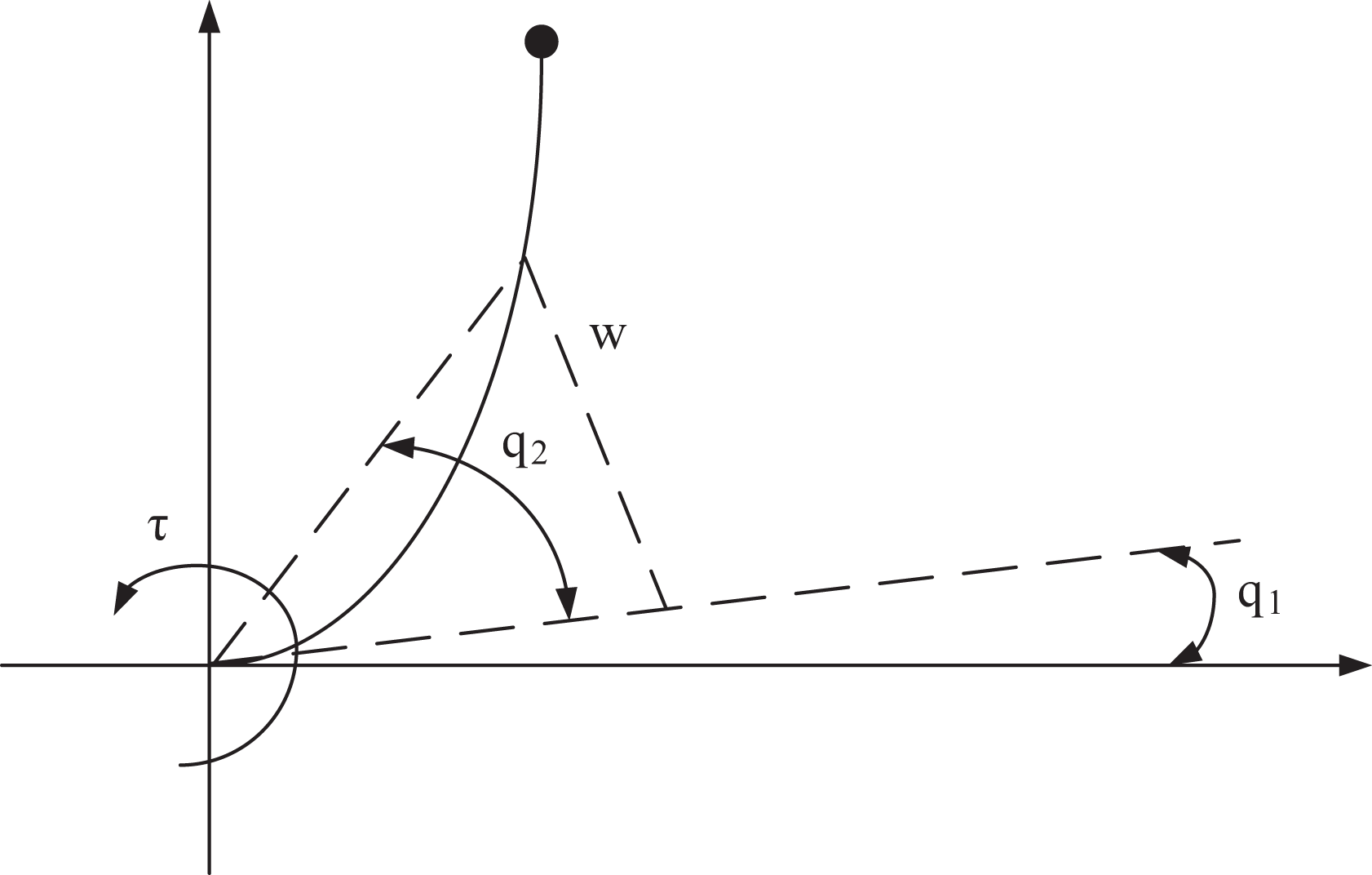
The flexible one-link robot system.
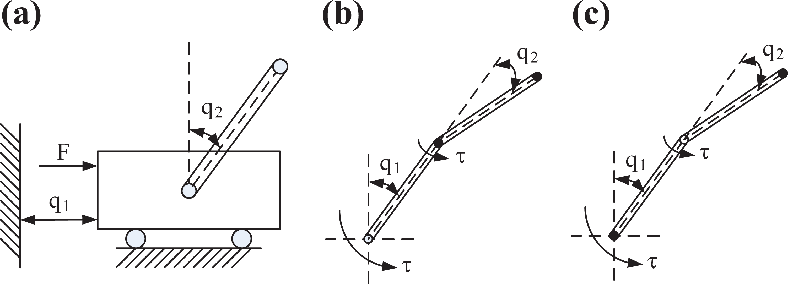
First- and second-order IP systems. (a) The cart–pole system. (b) The Acrobot system. (c) The Pendubot system. IP: inverted pendulum.
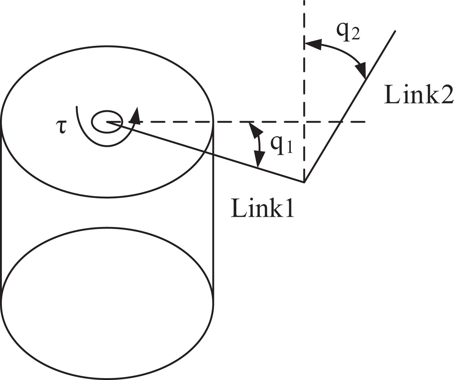
The rotating pendulum system.
Underactuated devices are expected to be more efficient, plain, and dependable than full-actuated devices. But the control of underactuated devices is more complex than full-actuated devices in theory. Non-holonomic systems and/or underactuated systems have been the common concern of many researchers in different disciplines. A lot of studies have been done on the control of these systems. Murray 35 outlined a non-holonomic control system. Experts in control and robotics have good research papers on dynamics and control of non-holonomic and/or underactuated mechanical systems. For instance, experts summarized some of the major advances in control of non-holonomic systems, which mainly studied non-holonomic systems with first-order non-holonomic constraints. 12 Wen 10 mainly studied the kinematic control problems. These studies and introductions show that the non-holonomic robot problem is the fusion of robots and mechanics, mathematics, nonlinear control theory, and other disciplines, which makes scholars of many different disciplines pay more attention to the research of non-holonomic robots. The research of non-holonomic robots has gradually become a research hotspot in the field of robotics.
The underactuated mechanism is a non-holonomic system, so the classification of UR could draw on the theory of non-holonomic systems. “Complete” and “non-integrity” are mechanical classification concepts of constraints and systems, while machinery is a mechanism and machine based on mechanical principles. The foundation of machinery is mechanics. In mechanics, the restriction on the shape and motion of the system is called constraint. The system with only complete constraints is a complete system, and the system with non-holonomic constraints is called a non-holonomic system. A robot with a non-holonomic constraint is called a non-holonomic robot, that is, a UR. From the point of view of analytical mechanics, non-holonomic robots are underactuated mechanical systems whose number of DOF is less than the dimension of their configuration spaces. How to exploit the “non-integrity” of constraints to develop a controllable UR is also a very meaningful work.
The characteristics of non-holonomic robots are mainly reflected in the non-holonomic constraint equations. Different non-holonomic constraints directly affect the motion planning and control methods of UR. According to the form of non-holonomic constrained equations, UR is classified into three types: first-order UR, second-order UR, and high-order (n > 2) UR, which is shown in Figure 6. Non-holonomic constraints of WMRs, space robots, and other robots generally appear as first-order differential equations, which are first-order UR. The joint of the robot with a UR arm (such as an IP) is subjected to a non-holonomic constraint, which is generally characterized by a second-order differential equation, that is, a second-order UR. The motion characteristics of the second-order UR system are different from those of the first-order UR system. Therefore, the research on the characteristics of non-integrity, controllability, and state feedback stabilization could not be used in the analysis design method of the first-order UR system. The motion of the first-order UR system could be reduced to a symmetric affine system. The motion of the second-order and high-order (n > 2) UR systems corresponds to the asymmetric affine system. In fact, the symmetric affine system is a special case when the deviation term of the asymmetric affine system is zero. They could all be regarded as nonlinear control systems.
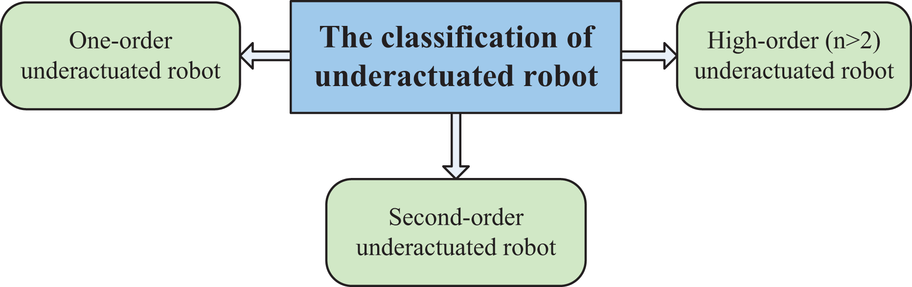
Classification by the form of non-holonomic constraint equations.
Mechanisms of UR
From the theory of mechanism kinematics, the mechanism has a certain movement when the number of the original moving parts of the mechanism is equal to the DOF of the mechanism. However, if the number of DOF of the mechanism is greater than the number of the original moving parts of the mechanism, the mechanism would move in the direction of the least resistance to movement. Such a mechanism is called an “underacting mechanism.” This section would study the common mechanisms of UR from four aspects: UR walking mechanism, UR arm, UR wrist, and UR hand, which is shown in Figure 7.

Commonly used mechanism of UR. UR: underactuated robot.
UR walking mechanism
All mobile robots have a common component, namely, wheels, tracks, legs, and other devices that support the robot to move. These devices, such as wheels, tracks, or legs, are called the walking mechanism of a robot system. Due to different applications, different mobile robots have different working environments and overall structures. In order to achieve smooth and accurate motion of the robot, a suitable walking mechanism needs to be selected. At present, there are four commonly used walking mechanisms: a foot-type walking mechanism, a crawler-type walking mechanism, a wheeled walking mechanism, and a mixing walking mechanism.
The foot-type walking mechanisms
Walking mechanism is a kind of mechanism used by walking robot. The movement of walking robot is to imitate the movement of human or animal. It could walk on the flat and uneven ground. It could even cross obstacles, up and down steps, and adapt to the environment. It has a relatively high degree of intelligence. It has mobility that other mobile robots could not achieve, which has unique superior performance. The nonlinear dynamic control for a novel one-legged hopping robot in flight phase is investigated. 36 Based on humanoid robots, Wang et al. 37 developed an adaptive feedforward control strategy to stabilize underactuated biped robots that walk on compliant ground. However, the study of walking robots is extremely challenging for designers and producers. Tang et al. 38 presented a walking manner of a spatial compass-like biped robot with underactuated ankles. This biped robot has three DOFs with only one actuator. The hip joint is equipped with a constraint mechanism. Lock the angle when it retracts to a desired value. Shao et al. 39 proposed a new method for synthesizing gait cam linkages. It could be used as a joint mechanism for URs. The main difficulty lies in the coordinated control of each leg joint, the attitude control of the fuselage, the steering mechanism and steering control, the effective transmission of power, and the mechanism of the traveling mechanism. There are many types of foot robots, which could be generally divided into two-legged robots and multi-legged robots.
The crawler-type walking mechanisms
Track-type walking gears are widely used to improve the ability of the wheels to adapt to soft ground and uneven ground. The crawler mode is also called the cyclic track mode. The greatest feature is that the circular loop track crawler is wound around a number of wheels, so that the wheel does not directly contact the road surface. And the road surface state could be buffered, so that it could walk on various road surfaces.
The robot adopts the crawler walking mode, which has the following advantages: It could climb a higher step due to the action of the angle of attack. The crawler has a strong driving force, and it is suitable for moving on the step. It could rotate in place. Therefore, it is suitable for moving in a narrow house. It is stable due to low center of gravity.
Tracked walking mechanisms are widely used in various construction machinery and military vehicles. The shortcoming of the crawler-type walking mechanism is that the turning is not as flexible as the wheel type. When the direction needs to be changed, the track driving mechanism on one side is decelerated or braked to realize the turning, or the reverse driving is to realize the in situ rotation of the vehicle body. However, this would cause the track to slide laterally relative to the road surface. It increases the energy consumption of the robot body and damages the road surface.
The wheeled walking mechanisms
The wheeled operating mechanism replaces sliding friction by rolling. Its main feature is high efficiency. Sun et al. 40 proposed a new type of transformable wheel-legged mobile robot that could be applied on both flat and rugged terrains. The wheeled travel mechanism is ideal for moving on flat roads. It has the characteristics of accurate positioning, lightweight, and simple production.
Most wheeled mechanisms are non-holonomic motion constrained drive systems. There are many types of wheeled movements, which are divided into single-wheel, two-wheel, and multi-wheel robots according to the number of wheels. At present, the most commonly used robots are three-wheel or four-wheel movement. In some special applications, there are also five or more robots, but the robot’s walking mechanism and control are complicated. 41 The kinematics model of a two-wheeled self-balancing autonomous mobile robot is shown in Figure 8.

Establishment of coordinate and structure figure of two-wheeled self-balancing mobile robot. 41
UR arm
The various movements of the arms are typically achieved by drive sources and various drive mechanisms. The arm bears the weight of the grabbed workpiece and the weight of the end effector, the wrist, and the arm itself. The structure, working range, flexibility, grasping force, and positioning accuracy of the arm all directly affect the working performance of the robot. Therefore, the structure of the arm should be determined according to the motion form, grasping weight, freedom of movement, motion accuracy, and other factors of the robot.
Straight arm movement mechanisms
The telescopic, lifting, and transverse (or longitudinal) movements of the robot arm all belong to the linear movement. The mechanism to realize the reciprocating linear movement of the arm is various, including the piston hydraulic (gas) cylinder, piston cylinder and rack and pinion mechanism, screw nut mechanism, and piston cylinder and connecting rod mechanism. Reciprocating linear motion could be driven by hydraulic or pneumatic piston hydraulic (air) cylinder. Due to the small size and lightweight of piston hydraulic cylinder, it is widely used in robot arm structure.
Arm rotation mechanisms
There are various mechanisms to realize the rotary movement of robot arm, such as vane rotary cylinder, gear transmission mechanism, sprocket transmission mechanism, and connecting rod mechanism. For example, the gear transmission mechanism drives the gear and the connected arm to perform a reciprocating rotational motion by the reciprocating motion of the rack, that is, the rotation of the arm motion.
Arm pitch motion mechanisms
The robot arm pitch motion is generally realized by piston hydraulic cylinder and connecting rod mechanism. The piston cylinder for the pitching movement of the arm is located below the arm, and its piston rod and arm are connected by hinge. The cylinder body is connected with the column by means of tail earrings or central pin shaft.
Compound arm movement mechanisms
The arm compound motion mechanism is mostly used for the special robot with fixed action program. It simplifies the robot’s transmission structure, the drive system, and control system. The arm compound motion mechanism makes the robot drive accurate and reliable, so it is widely used in production. In addition to the compound motion of the arm, the motion of the wrist and the arm could form the compound motion.
According to the movement path of the arm (i.e. the route) or the movement requirements of the arm and the wrist, the compound motion of the arm (or wrist) could be combined by the power components (such as piston cylinder, rotary cylinder, rack piston cylinder, etc.) and the commonly used mechanism (such as groove mechanism, connecting rod mechanism, gear mechanism, etc.).
UR hand
Experts have studied different types of robotic hands to achieve object capture and processing. Several successful designs for human and nonhuman hands have been developed in the past. The Stanford/Jet Propulsion Laboratory (JPL) Hand 42 was a representative robot at that time and now. The dexterous hand has three fingers for a total of nine DOFs. The Stanford/JPL hand’s contribution to the multi-finger hand is the multi-joint, multi-DOF modular structure design, and more important. It has completely introduced sensor systems such as position, touch, and force for the first time. Therefore, the era of multi-fingering perception of the external environment began. And the first step of the actual grasping operation of the multi-finger hand was created. Both the German Aerospace Center I (DLR I) Hand and the German Aerospace Center II (DLR II) Hand 43 are multi-sense, sensory integrated, mechatronic multi-finger dexterous hands. The DLR I hand transmission mode and the large number of analog signals have led to a reduction in reliability and an increase in maintenance difficulty. Based on the DLR I dexterous hand, the DLR II dexterous hand is more powerful and more reliable. It is considered to be the best dexterity in the world at the time. The BUAA Hand 44 has high flexibility of movement and strong force sensing capability. All actuators are integrated into the finger module based on the modular design strategy. Based on the kinematics and mechanical design of Manus Colobi, Colobi Hand 45 is a robot developed for industrial applications. Barrett Hand 46 is a multi-finger programmable gripper with great flexibility. It protects target objects of different sizes, shapes, and orientations. The Tokyo University of Agriculture and Technology (TUAT)/Karlsruhe Hand 47 possesses 20 DOFs and is driven by one actuator which could be placed into or around the hand. The Turin Hand 48 is a pneumatic hand consisting of four fingers and an opposite thumb. The features of adaptive grasp, curling fingers, and a rotational thumb have increased the mechanical functionality of this Toronto/Bloorview MacMillan (TBM) 49 Hand that exceeds the traditional prosthesis. The strengthening and stretching for rheumatoid arthritis of the hand (SARAH) 50 was developed as a potential tool for special purpose manipulators on the International Space Station. It is suitable for adaptive and reconfigurable space applications. Because the springs are placed inline with the actuators and fingers, the Massachusetts Institute of Technology Hand 51 exhibits a low mechanical impedance. This low impedance increases the mechanical robustness of the hand, allowing people to safely operate the hand in environments that are not well known. The RoboCasa Hand-I (RCH-I) 52 is a new type of human hand that could be integrated with a humanoid robot platform. It enhances communication between robots and humans. Wu et al. 53 proposed an equivalent mechanism for deducing the underactuated finger mechanism under different gripping conditions based on the principle of minimum damping. Liu et al. 54 designed a scalable underactuated cable truss-type mechanical gripper that could be used in the field of space robots. Xu et al. 55 proposed a combined continuous mechanism for anthropomorphic robots, which could generate any number of translational outputs by linearly combining two independent inputs. Most of the available multi-fingered prototypes have a large amount of DOFs, complex actuation, and high cost. Most of these hands are still used to enhance applications, laboratory tests, or research projects. However, it could be used availably in industrial and nonindustrial applications even in the market, such as the Barrett Hand, SARAH Hand, and Robosoft Hand.
Many robotic hands focus on simulating the overall appearance and movement of a biologic hand, while ignoring other equally important features, such as size, weight, and real-time control. Those traditional manipulators (such as those in Qian and Zhang 56 ) are relatively complex, large, and heavy. It is difficult to install on robots as large as humans. Based on the manipulator kinematics model of D-H method, He et al. 57 proposed kinematics simulation and numerical simulation based on rigid–flexible coupled virtual prototype. Taking the design of the five DOFs manipulator as an example, it is proved that the method obviously contributes to the lightweight design of the manipulator. The rigid–flexible multi-body system is a hot topic in recent years. Based on the rigid–flexible coupled virtual prototype, He et al. 58 –61 carried out modeling, simulation analysis, and numerical simulation for different types of prototypes. This method is of great significance for the mechanical design and dynamic analysis control of multi-body systems in the future. The traditional robotic hands are also very expensive and difficult to manufacture and maintain. Because the robotic hand has many DOFs, drivers and control systems are large and difficult to control. In a sense, a robotic hand with more DOF is more dexterous. And the DOF directly determines the ability of the hand to bend around the object and adapt to the shape of the object.
How to reduce volume, weight, and power costs is an important aspect of designing robotic hands. Therefore, designing a robotic hand that drives less becomes an interesting direction. However, it becomes a challenge that how to design a robotic hand with feature of compact, low cost, and easy operation but still keep the number of DOF to support the ability of grasp adaptively different objects. A popular research method uses the underactuated mechanism of the finger. A new type of fully rotating joint linkage-based underactuated mechanism is proposed. A new method based on the minimum resistance law to realize the equivalent mechanism under different contact conditions of the finger is proposed. And the kinematics analysis based on the equivalent mechanism was given. 62 Gao et al. 15 proposed a 3-RRS (R represents a rotating pair and S stands for spherical side) parallel mechanism based on the generation of underactuated parallel joints that is shown in Figure 9. Ha et al. 63 developed a mathematical analysis model of contact forces for the underactuated finger in a general UR hand during grasping. By using springs and mechanical constraints, the underactuated concept in robotic grip allows the hand to adjust itself to an irregularly shaped object without complex control strategies and sensors and with actuators less than DOFs.

3-RRS parallel mechanism for underactuated parallel joint. 15
Based on comprehensive domestic and foreign literature, the mechanisms commonly used for underactuated finger design schemes are differential mechanism (seesaw mechanism, t-pipe mechanism, movable pulley mechanism, connecting rod mechanism, planetary wheel mechanism, etc.), compatible mechanism (generally composed of springs, tendons, and some flexible materials), trigger mechanism, passive mechanism, and so on. The underactuated finger of the tension drive (or friction wheel drive) could only achieve a small grip. In order to realize underactuated humanoid fingers with compact structure and large grasping force, underactuated linkage mechanism is generally used to design and make robot fingers.
Currently, there are two main types of underactuated finger mechanisms, namely, tendon-actuated mechanisms and linkage-based mechanisms. 64 A typical tendon drive mechanism makes it easy to build a compact structure. However, the tendon drive mechanism could only exert a small grip. Another disadvantage of the tendon system was that they were strongly influenced by friction and elasticity. 65 Massa et al. 66 and Carrozza et al. 67 studied the tendon mechanism of the underactuated prosthetic hand. The optimal design issues associated with pulley diameter and position were discussed. 68 Two DOFs/one actuator referred to an isotropic force characteristic. 69 Here, the isotropy of force means that the strength of the force applied to the center of each phalanx and the object being grasped is the same. Dechev et al. 49 described a prosthetic hand with a passive adaptive gripping mechanism—TBM Hand. Carrozza et al. 70 also gave some preliminary results regarding the tendon-driven underdrive mechanism and the compliant joint prosthesis.
UR wrist
Current research has focused on rigid and fully powered robotic wrists, which are always a multi-body system that affects the accuracy of workspace analysis and simulation. For the synthesis of the mechanical structure of multi-body systems, He and Huang 71 presented a new systematic kinematic state-based methodology for the functional synthesis of mechanisms with consideration of cost. He and Hua 72 presented a new systematic dynamic programming-based methodology for the synthesis of mechanisms integrated with force and motion transformation. He et al. 73 presented a new systematic dynamic programming-based methodology for functional synthesis of mechanisms with the considerations of mechanical efficiency and cost. He et al. 74 were devoted to a systematic weighted directed graph-based methodology for automated synthesis algorithm of mechanisms under mechanical efficiency consideration. For modeling of prototypes or products, He et al. 75,76 are working on a new computational co-evolutionary product design approach. An undirected graph of the mechanical parameters is proposed to simulate the relationship between the design parameters. Parametric design methods are used to solve design and analysis problems. After he proposed the first UR wrist in the world, He et al. 77 proposed a workspace analysis model for a new UR wrist based on virtual prototyping. The numerical simulation analysis of the wrist dynamics of UR based on virtual prototype is introduced in detail. The peak value of the servo motor in the articulation unit was also estimated. 78 The inverse kinematics analysis and forward kinematic analysis of the UR wrist with numerical simulation based on virtual prototyping were discussed in detail. 79
He et al. 80 proposed a loop selection rule and applied the loop increment method to the accuracy analysis of a spherical three-DOF parallel UR wrist. Combined with the particularity of the spherical wrist structure and the versatility of the D-H parameters, Wang et al. 81 proposed a fast and accurate parameter identification method for wrist calibration. Prof. He has important research and contributions in the field of three-DOF parallel robot wrists. He et al. 82 –85 invented several new three-DOF UR wrist devices based on ball hinges and spherical spaces. The utility model has the advantages of simple structure, low cost, lightweight, small volume, easy processing, and easy maintenance. It could be used as a robotic arm or a robot arm with multiple series mechanisms. On this basis, He et al. 86 –88 designed and invented the novel UR wrist based on the centering mechanism and non-holonomic constraints, which has the characteristics of flexible movement, compact structure, and good rigidity. It could be used as the joint of the robot. The novel UR wrist could be used in parallel robots, micro-motion robots, and the like. The robot wrist 89 –93 was used to connect the robot arm and the end effector, so that the end effector could achieve a certain gesture in the working position. Therefore, the wrist of the robot could be described as the positioning mechanism of the robot. The robot wrist is an important and complex structure of the robot, whose flexibility directly determines the type and complexity of tasks that a robot could accomplish. Therefore, it is necessary to research the robot wrist. 94 Robots need six DOFs to achieve any position and attitude in the working position, and their wrists should have three DOFs. The robot wrist could be either serial or parallel mechanism. 95 –97 The wrist of the serial robot is composed of the kinematic chain of RRR mechanism (R stands for the rotating pair). Structure diagram and three-dimensional (3-D) model of three-DOF UR wrist are shown in Figures 10 and 11.

Structure diagram of three-DOF UR wrist. 61 DOF: degree of freedom; UR: underactuated robot.

Three-dimensional model of 3-DOF UR wrist. 62 3-D: three-dimensional; DOF: degree of freedom; UR: underactuated robot.
In Figures 10 and 11, the wrist of a parallel robot is composed of multiple kinematic chains, which could accomplish tasks more accurately than that of a serial wrist. 91,98 Actuators of parallel robot wrists could be easily isolated from the operating space by placing it on a fixed base. The parallel robot wrist has a high stiffness configuration in almost all of its workspace and a reduced working space. There are two basic types of robot wrist mechanisms.
Serial mechanism
Three DOFs could be achieved by using an open-loop kinematic chain, while requiring three power sources to move. Sometimes, it is also reduced to two DOFs. The loss of DOF could be compensated by other DOF from the robot arm. 99 Most continuous wrists in robot have three rotating joints. Chablat and Angeles 100 proposed a universal n-revolute spherical robot wrist and studied the existence of redundant isotropic structures in the wrists of four rotating series of spherical robots.
Parallel mechanism
The movement of the wrist of the three-DOF parallel robot resembles the real wrist with different characteristics.
101
–103
The simple feature is the 3-RRR mechanism, which has three rotating joints per leg. The structure of the parallel mechanism is relatively simple compared to the structure of the bionic mechanism. The spatial layout is more compact than the series mechanism. Compared with the single motion mechanism, it is more compact than the actual wrist movement. Therefore, it has advantages in the design and selection of robot wrist. Meanwhile, underactuated parallel mechanism is used to reduce the number of drivers and the costs of control and hardware with the development underactuated researches. This article presents a new underactuated parallel robot wrist with 3-RRR characteristics. The current underactuated mechanism research has three main characteristics: Mechanism innovations are mainly concentrated on underactuated fingers, while UR arms and wrists are rarely innovative. At present, the research of underactuated mechanism is still in the plane state. Space underactuated mechanism is one of the study directions in the future. The reachable workspace and mechanism tolerance of the underactuated mechanism is one of the main study directions.
The mechanism of the UR, from concept design to prototype or product, should be designed based on the low carbon concept for sustainable product design. 104 Sustainable product design is one of the most effective ways to achieve cleaner production, especially considering the environmental impact of the product. Because cleaner production is a recent concern for global manufacturing. 105 The environmental footprint of most products is determined during the design phase of their life cycle, especially in conceptual design. However, it is difficult to achieve a solution assessment of the product’s environmental footprint by unconfirmed product information in conceptual design. 106 He et al. 107 are working on a product carbon footprint estimation model based on unascertained mathematical theory. The product carbon footprint of the modular underactuated exoskeleton robotic mechanism is given as an example to illustrate the proposed method. He et al. 106 used the unascertained measurement model to evaluate the conceptual design of the product environmental footprint. Taking the conceptual design of the offshore wind power installation platform as an example, the method is helpful for the design evaluation of the product environmental footprint conceptual design.
After the design of the electromechanical concept of the UR mechanism is completed, a product sustainability assessment is required. Product sustainability assessments are progress in assessing sustainability, including indicators of product sustainability throughout the product life cycle. He et al. 108 proposed a grading evaluation system for the sustainability assessment of mechanical products using energy, environmental, resource, technical, and economic indicators. The product carbon footprint of the modular underactuated exoskeleton robot mechanism is used to demonstrate the proposed method.
Control methods of UR
In the early 1990s, in the theory of nonlinear control, the control of underactuated systems once attracted widespread attention and study. So far, the control of underactuated systems has been studied mainly by point stabilization, trajectory tracking, and path tracking. The strong coupling and high nonlinearity of underactuated systems make their control more difficult.
In the development of robotics for more than 30 years, almost all design methods that could be provided from classical to modern control theory have been tried on UR. On the basis of summarizing the predecessors, the researchers developed various control strategies to solve the control problem of UR. However, most of these control strategies are based on accurate mathematical models in mathematical theories, which make it difficult for most control theories and strategies to be used in UR systems.
Usually, the control of the underactuated part of the underactuated mechanical system is realized by using motion coupling or dynamic coupling. 8,22,28,35,109 –117 Zhang et al. 118 presented a torque-coupled control strategy to solve the stabilization control problem for a class of n-DOF (n ≥ 3) underactuated mechanical systems. Examples of utilizing motion coupling are first-order non-holonomic systems, such as WMRs and smart robotic hands. The equations of these systems are drift-free with inputs entering linearly. A second type of system characterized by dynamic coupling is provided by many examples: crane systems, the classical cart–pole system, Acrobots, and manipulators with flexible elements. The second type of equation includes drift terms for gravity, centripetal, Coriolis, and/or elastic forces whose inputs are affine. Underactuation does not always mean uncontrollability. Whether or not it is controllable depends on the structure of the system under consideration. All previous examples are controllable. However, in the case of a planar manipulator with a free joint, 112,113,115,116,119 –121 the linearized equation at any operating point is uncontrollable.
Some researchers have studied underactuated systems with passive joints. Arai and Tachi 22 demonstrated that the number of active joints should be equal to or greater than the number of passive joints to control the passive ones. A Cartesian space controller was also designed to achieve the desired set points for all joints. 114 Saito et al. 28 developed a two-link underactuated arm robot that could be moved along the crossbar with just one actuator. Bergerman and Xu 122 studied the variable structure control of a three-link manipulator with a passive joint in both joint and Cartesian space.
Compared with systems using passive joints, it is very rare to control systems that have free joints. Working with a PFL and energy-based method, Spong 8 studied the vibration control problem of Acrobot. Recently, a scholastic work by Nakamura et al. 111 –113,116 investigated the application of periodic oscillations to control the manipulators with free joints. Oscillation control based on Poincaré mapping analysis also appears in the study by Suzuki et al. 113 De Luca et al. 123 proposed a constructive open-loop control strategy involving nilpotent approximations and iterative steps.
Then, because fewer actuators reduce costs and weight, the control of the robot systems with an underactuation property is more attractive. There are many UR systems in practical applications, such as pendulum systems, 124 –126 ball-and-beam systems, 127 –129 and power line inspection robotic systems. 122,130 –133 However, the controller designs of UR systems are more complex than fully actuated robot systems, especially UR systems could cause performance degradation when subjected to external disturbances. In recent years, controller design of uncertain UR systems has attracted widespread attention, and various control algorithms have been proposed, such as sliding mode control (SMC), 134 –139 backstepping control, 140 –144 and robust control and adaptive control. 145 –147
The control of UR would be discussed in the following two control methods: open-loop control and closed-loop control. The UR has the feature that the number of independent generalized coordinate change is less than the number of its generalized coordinates, that is, the number of DOF is less than the dimension of the spatial space. Then, from the perspective of control theory, the concern is how to control the shape or motion of the UR with less control input than the dimension of the UR’s positional space for a controllable UR.
Open-loop controls
Open-loop control is interesting for several reasons. It is an essential technique for automation. Open-loop control could offer cheaper and faster control for some operations. Vibratory feeders and sorters, and the remote center compliance device for peg in the hole insertions, are good examples. Open-loop stable strategies may be used as a core around which closed-loop control is organized. This may make open-loop control more robust by reducing the demands on the feedback controller. Finally, understanding open-loop stable strategies may aid in understanding the key features to be learned by a UR.
Open-loop control of chain systems
The simplest chain system is a so-called single-chain system with two inputs, n state outputs. A chain system with more than two inputs is called a multi-chain system. Open-loop control methods widely used in chain systems include time polynomial input control and trigonometric function input control. The feedback control method adopted has the characteristics of optimal control. For the chain system, the time polynomial input control is a relatively simple control method, which could be obtained by solving the solution method of the undetermined coefficient method. It is easy to obtain a smooth system motion. The trigonometric function input control is a step based on the optimal control principle. The trigonometric function input control is a step-by-step control method. When the output state of the chain system is large, the output state of the pre-control to the target value would change around the target value in the subsequent control, making the stability of the system poor. The open-loop control method is implemented. The smoothness of the system motion is poor. Murray et al. 35,148,149 studied the trigonometric function control algorithm of a chain system.
Open-loop control with oscillating input
An open-loop control for underactuated mechanical systems using an oscillatory input with amplitude and frequency modulations 131 is studied. Once all of the actuating joints have moved to their desired positions, an oscillating input is applied to the actuating joint to move the remaining underactuated joints. The steering force of the underactuated joints is achieved by utilizing the dynamic coupling between actuated and underactuated joints. This dynamic coupling occurs due to the oscillatory motions of the actuated joint. Once the frequency of the oscillatory input is determined, the amplitude is decided by analyzing a time-invariant system derived from the underactuated joint dynamics by the method of averaging. By generating equations and coordinate transformations derived from the generated equations, a systematic approach is proposed for converting underactuated joint dynamics into a standard average form. In the event of an actuator failure in the external space, the failed joint could be manipulated by adopting the proposed method.
Closed-loop controls
The closed-loop control system is also called the feedback control system. The relationship between input and output is established through feedback. The controller could implement predetermined system functions by determining control strategies based on actual conditions of the inputs and outputs. Feedback is one of the most important basic concepts in cybernetics. It is characterized by adjusting future behavior based on past conditions.
The working principle of a typical UR closed-loop control system: The control system sends commands to the comparator, and the sensors are mounted on the terminal tools (tachometer, photoelectric encoder, resolver, high-precision potentiometer, proximity sensor, force sensor, pressure sensor, sliding sensor, contact sensor, etc.). The error value is obtained by comparing the feedback signal of the actual state of the robot and amplifying it. The driving source is used to make the UR control a certain link to perform corresponding action. The new motion state of the driving robot is sent to the comparator for comparison again. The newly generated error signal continues to adjust the motion of the UR. Then the process continues until the error information is zero.
According to the different functions and characteristics in the UR system, the feedback could be divided into negative feedback and positive feedback. The feedback signal of negative feedback is opposite to the polarity of the input signal or the direction of change is opposite (inverted). The result of the superposition would weaken the net input signal. The feedback signal of positive feedback is the same as the polarity of the input signal or the direction of change is in phase. The result of signal mixing would cause the amplifier’s net input signal to be greater than the output signal. Negative feedback causes the output to act in the opposite direction to the input, so that the error between the system output and the system target is reduced. So the system tends to be stable. The positive feedback causes the output to function similarly to the input, causing the system deviation to increase and the system to oscillate. Positive feedback is mainly used for signal generation circuits. Automatic control systems typically stabilize the system’s operating state by negative feedback techniques. Closed-loop control is studied from the following aspects, which is shown in Figure 12.

Closed-loop control methods for UR. UR: underactuated robot.
Control methods based on fuzzy systems
Takagi and Sugeno proposed a fuzzy model to describe complex systems. There are three kinds of fuzzy methods: Takagi–Sugeno (T-S) fuzzy system, Mamdani fuzzy inference system, and type-II fuzzy system. 150
Fuzzy control
Fuzzy control is an early form of intelligent control. It absorbs the ambiguity of human thinking and controls objects by using the control experience of human experts. Fuzzy control does not require a mathematical model. Fuzzy control is an effective way to solve the uncertain system control. Fuzzy control also has its own shortcomings: the control precision of fuzzy control is low. The membership function and control rules of the fuzzy controller are pre-summarized based on experience. It could not be corrected during the control process and does not have the ability to learn and adapt.
Many scholars have made a lot of improvements to traditional fuzzy control. Various forms of fuzzy control have been developed. Fuzzy models and identification, adaptive fuzzy control, and so on have emerged. And progress has been made in stability analysis and robust design. Yu et al. 151 proposed a simplified nonlinear fuzzy controller integrating an improved 3-D guidance law. In order to address the problem of path following for an underactuated autonomous underwater vehicle (AUV) exposed to unknown environmental disturbances, Li et al. 152 address the problem of trajectory tracking control for underactuated AUVs in three dimensions space. Fuzzy control based on model and analysis method has become a modern fuzzy control, which brings new vitality to fuzzy control.
The process for fuzzy inference of an output Y in Figure 13 requires several steps. The input X is fuzzified into sets. The output sets V are generated by the inference engine based on the fuzzy rules. Y is the “real world” output which is retrieved through the defuzzification of V. For fuzzy systems, there are three methods such as model-based fuzzy control, model-free fuzzy control, and hybrid fuzzy control.

Diagram illustration of fuzzy system. 153
a. Model-based fuzzy control
The T-S fuzzy system is a special type of fuzzy logic system. Its fuzzy rules are different from the general fuzzy rule forms. The output of the T-S fuzzy system is still accurate without the blur canceller. The advantage is that the output could be represented by a linear combination of the input values. Therefore, the method of parameter estimation could be fully utilized to determine the parameters of the system. At the same time, the analytical method of the linear control system could be used to approximate the analysis and design of the fuzzy logic system. A disadvantage of this system is that the output portion of the rule does not have the form of a fuzzy linguistic value. Therefore, expert knowledge could not be fully utilized. The freedom of application of the various principles of fuzzy logic in this system is also limited.
The research on T-S fuzzy system includes two aspects: T-S fuzzy system modeling and T-S fuzzy system control.
Based on the T-S fuzzy model, Ma and Sun 154 studied the stability of nonlinear systems. And the effectiveness of the new method for nonlinear system output tracking and adjustment problems is proved by numerical simulation. Begovich et al. 155 combined the linear regulator theory with the T-S blur method. A method for realizing trajectory tracking of nonlinear systems is proposed. And the algorithm used for this tracking is described. Li et al. 156 designed a fuzzy controller for keeping the first link periodically oscillating while the second link remains vertically standing. Therefore, the stunt control of the Pendubot underactuated two-link robot is realized. Lee 157 presented a new direct discrete-time design methodology of a sampled-data observer-based output feedback (OFB) fuzzy controller for a class of nonlinear system that is exactly modeled in T-S’s form at least locally. Xu et al. 158 presented a novel implementation of a T-S-type fuzzy logic controller (FLC) on a two-WMR, which consists of two wheels in parallel and an inverse pendulum. The controllability property for a class of T-S fuzzy models is analyzed, while a fully nonlinear stabilizer is designed in a practical way. 159
b. Model-free fuzzy control
Model-free fuzzy control is a heuristic method based on human experience and knowledge. Nalley and Trabia 160 designed a distributed FLC for each subsystem of the crane. Control is then distributed to multiple controllers. This makes it easier to identify fuzzy rules and collections. In order to improve the stability of UR, a new fuzzy logic control method for swing and balance control is proposed. Two independent fuzzy inference control laws are used for swing and balance control tasks. The fact shows the feasibility of fuzzy control methods in the application of nonlinear systems. 161 Based on the nonlinear model of crane, Mahfouf et al. 162 proposed an FLC with two rule bases for anti-sway control of bridge cranes. A novel amplitude-saturated OFB control method is used for underactuated crane systems with double pendulum effects. 163 Cho and Lee 164 designed a new fuzzy anti-swing control scheme for 3-D bridge cranes. The control scheme includes position servo control and fuzzy logic control. The robustness and effectiveness of the control are verified by experiments. It could be concluded that this control scheme has great potential for the anti-swing control of industrial 3-D bridge cranes. Based on the new continuous- and discrete-time models developed by polar coordinate transformation, Raimondi and Melluso 165 proposed a new fuzzy/Kalman closed-loop fuzzy motion control system for underactuated remotely operated vehicle. Khizer et al. 166 detailed the dynamics model of a small unmanned helicopter. Based on the nonlinear control technology of professional knowledge, the stable hover flight control of small unmanned helicopters in light air turbulence environment is proposed. Using a combination of expert knowledge and pilot-based experience, a stable inner- and outer-loop fuzzy control was designed. This control is used for attitude, altitude, and position. Based on the characteristics of the system and the desired motion, Trabia et al. 167 proposed a new method of inverse dynamics for adjusting the input and output variable ranges of three FLCs. The relative shape and distribution of the membership functions relative to each other remains fixed. The proposed method could be extended to other dynamic systems. It has the advantage of avoiding guessing the acceptable range of fuzzy variables. Based on the cart–seesaw and IP system, Lin et al. 168 proposed a new type of laboratory instrument called the cart–pendulum–seesaw system. Unlike other model-based methods, the proposed fuzzy control method does not require accurate measurement of all state parameters. In addition, it is robust to parameter variations and other disturbances in the system. Based on the Lyapunov stability criterion, Hashemnia et al. proposed a stable fuzzy controller for stabilizing the motion of unmanned bicycles. 169 The Mamdani-like output recurrent fuzzy control strategy with a low-level microcontroller for the wheeled conveyance platform was presented in this study. A necessary condition based on the Lyapunov stability analysis is established to guarantee the system stability. 170
c. Hybrid fuzzy control
In order to combine the advantages of the Mamdani fuzzy system and the T-S fuzzy system, some researchers combined the Mamdani fuzzy system with the T-S fuzzy system to design a controller for the complex UR system.
Since the ball plate system is an extension of the traditional ball and beam problem, Fan et al. 171 proposed the trajectory planning and tracking problem of the ball plate system. Based on this problem, this article proposes a hierarchical fuzzy control scheme. This solution is used to solve the trajectory planning and tracking problems of the ball and board system. The program consists of three levels. The lowest level is the T-S-type fuzzy positioning controller, the middle level is the fuzzy supervisory controller, and the top level is the fuzzy plan controller, which is used to determine the required trajectory. Huang et al. 172 introduced the design and implementation of a two-wheel IP system with a fuzzy control scheme and the system-on-a-programmable-chip technology. The control scheme includes three kinds of fuzzy controls which are the fuzzy balanced standing control, the fuzzy traveling and position control, and the fuzzy yaw steering control. Lin et al. 173 developed a balancing approach for a novel super articulated mechanical system model, which called the cart–seesaw system, using fuzzy logic and fuzzy coordinator compensation to drive the sliding carts and keep the seesaw angle close to zero in the equilibrium state. Xu et al. 174 proposed synthesized design of an FLC for control of an underactuated unicycle system. The FLC objective is velocity control of the wheel while keeping the pendulum upright, which is an unstable equilibrium. Through the intensive simulations and comparisons, the effectiveness of the proposed FLC is validated.
Fuzzy control based on traditional control
a. Fuzzy PID composite control
Fuzzy proportional–integral–derivative (PID) composite control is a combination of fuzzy technology and conventional PID control algorithm to achieve higher control accuracy. Fuzzy control is used when the temperature deviation is large. It has the characteristics of fast response and good dynamic performance. PID control is used when the temperature deviation is small. It has good static performance and meets system control accuracy. Therefore, it has better control performance than a single fuzzy controller and a single PID regulator. In the control of the UR system, the mainstream PID control method has parallel PID and cascaded PID.
There are four improved parallel PID control methods for fuzzy systems. First, the input set of the fuzzy system is obtained based on the PID control. Sanchez and Flores 175 introduced a new fuzzy PI + PD controller, which includes a dynamic switching fuzzy system. This scheme is able to implement real-time swing-up control for the Pendubot, with a very good performance. Second, the PID control law is used as the output sets of the fuzzy system. Based on the novel idea of controlling and stabilizing the IP via vertical forces, Maravall et al. 176 studied the excellent effects of vertical forces on IP stability. They also demonstrated how the fuzzy control design method could be used to construct a hybrid fuzzy control system. The system incorporates PD control into the T-S fuzzy control structure to stabilize the IP by vertical force. Third, the PID control parameters are adjusted by the fuzzy system. Solihin et al. 177 proposed a fuzzy-tuned PID controller design for anti-swing gantry crane control. The proposed fuzzy-tuned PID controller has an advantage of robustness compared with original PID control. Xiang et al. 178 also adaptively adjusted the parameters of the PID controller using three fuzzy systems. A 3-D guidance controller for underactuated AUV is presented to guarantee the stability of path following in the kinematics stage. In the dynamics phase, a heuristic adaptive fuzzy algorithm based on the pilot command and feedback linearization PID controller is developed. The sensitivity analysis of the heuristic fuzzy controller is presented. El-Bardini and El-Nagar 179 proposed the interval type-2 fuzzy PID controller to control an IP on a cart system with an uncertain model. The two proposed controllers have been tested using four simulation tasks. The simulation and practical result shows that the performance of the proposed controller is significantly improved compared with the type-1 fuzzy PID controller. Omni-directionally balanced mobile robots are also controlled by cascaded PID methods. 180 –182 Hamza et al. 183 presented the design of an optimized interval type-2 fuzzy PD controller in cascade form for rotary IP system. The proposed control strategy could be regarded as a promising strategy for controlling different unstable and nonlinear systems.
b. Adaptive fuzzy control
After nearly 50 years of development, fuzzy control theory has been more and more widely used in practice. Adaptive fuzzy control is formed by combining fuzzy logic technology with adaptive control. An adaptive fuzzy SMC strategy is presented to achieve position control of underactuated manipulators. 184 It is robust, easy to master, and operate. And the control technology overcomes the difficulty of accurate modeling of complex nonlinear systems. It is possible to further correct the control rules in the controller according to its own output and external feedback during the control process. It makes the control effect more perfect. Therefore, adaptive fuzzy control has received more and more attention in modern industrial production and aerospace.
It studies the 3-D trajectory tracking control problems for underactuated AUVs in the presence of parametric disturbances and external disturbances. 185 Based on the speed control strategy and the adaptive integral SMC algorithm, an adaptive robust controller is proposed. 186 Based on a novel Nussbaum-type function, Huang et al. 187 proposed an adaptive control scheme for a class of strictly feedback nonlinear systems. The problem of underactuating the AUV path was solved. The goal is to deal with parameter uncertainty and current disturbances. An adaptive robust control system was proposed by fuzzy logic, back push, and SMC theory. Zeng et al. 188 proposed a nonlinear adaptive line-of-sight path following controller for underactuated AUVs in the presence of ocean currents. Lai et al. 189 presented a fuzzy control method for the motion control of an Acrobot. A fuzzy controller is designed to solve the singularity problem and improve the control performance by adjusting the design parameters in the control law. Chang 190 provided an effective all-purpose adaptive fuzzy controller for the crane. This proposed method does not need the complex dynamic model of the crane system, but it uses trolley position and swing angle information to replace the design of fuzzy controller. It is more straightforward to implement algorithms that reduce computational complexity in practical environments.
c. Switching the fuzzy control
Switching fuzzy control is to design a switching controller for the system. And the sub-controller of the switching controller is the control method of the fuzzy controller. A continuous state feedback controller is constructed using the switching technique and the Lyapunov function method. 191 This makes the closed-loop system asymptotically stable for all allowed uncertainties. Switching fuzzy control method is a new type of important hybrid control method. It is a new control method based on switching system theory and fuzzy system theory. It has important theoretical value and broad application prospects.
d. Supervisory fuzzy control
For complex nonlinear real-world systems, fuzzy controllers require multiple layers of controllers to effectively achieve control objectives. The monitoring controller describes the current state of the system through various available data and improves the control performance of the system.
Fuzzy control based on artificial intelligence
Fuzzy control is a kind of computer numerical control based on fuzzy set theory, fuzzy linguistic variables, and fuzzy logic reasoning. From the perspective of linear and nonlinear, fuzzy control is a kind of nonlinear control. From the intelligence of cybernetics, it belongs to the category of intelligent control. At present, more and more studies integrate neural networks into fuzzy logic systems of UR systems through neural fuzzy control and fuzzy neural networks (FNNs).
a. FNN control
Krishnamurthy and Ward 192 defined a fuzzy nervous system. In the literature, 193 –199 FNNs could be successfully used for the control of UR systems. Kim and Chwa 200 proposed an obstacle avoidance method in the position stabilization of the WMRs using interval type-2 FNN. This significantly improves the behavior of the robot. A robust adaptive NN-based OFB control scheme is presented for a dynamic positioning ship with uncertainties and unknown external disturbances. 201 A tracking control of a real IP system is implemented in Lu et al. 202 via an adaptive self-constructing FNN controller. Concurrently, the adaptive laws are derived based on the sense of Lyapunov so that the stability of the system could be guaranteed. Both fuzzy control and neural network control have been applied to the control of robots. Fuzzy control uses the experience of human experts to control precise models that do not require objects. Fuzzy control could handle nonlinearities and uncertainties in robot control. Neural network control has self-learning capabilities. Applying it to the control of the robot could well overcome the effects of uncertainties, such as environmental changes and load changes. Neural network control and fuzzy control are combined. Fuzzy reasoning is realized by neural network. It could make the neural network have the ability of self-reasoning and induction.
Many studies in recent years have proved the commonality of fuzzy logic inference and neural network, which provides a theoretical basis for the application of FNNs. Both the fuzzy system and the neural network system have the function of a general adaptive model-independent estimator. Then there are many commonalities between them. Because of these theoretical commonalities, neural networks could implement fuzzy logic reasoning.
b. Optimization based on fuzzy control
Inappropriate control parameter causes instability in underactuated systems relative to other nonlinear systems. Based on expert knowledge, the optimal control parameters could not be obtained efficiently. Therefore, some other optimization algorithms are needed to improve the control performance.
Martínez et al. 203 designed a trajectory tracking controller taking into account the kinematics and the dynamics of the autonomous mobile robot using type-2 fuzzy logic and genetic algorithms (GAs). GAs are used for the optimization of the constants for the trajectory tracking and optimization of the parameters of membership functions for fuzzy logic control. A simple FNN controller with limited torque is developed for upswing control of the Acrobot. The antecedents and consequences of the FNN controller are optimized simultaneously with an improved GA. 204 The main contribution 205 is to propose the GA-based fuzzy sliding model controller with a modified adaptive law for robust control of an uncertain and nonlinear plant.
Partial feedback linearization
A useful technique for controlling a UR system is the so-called PFL. 206 Spong proposed a PFL method for underactuated systems, which implements system transformation by defining a new control quantity. It is finally linearized locally. This method is widely used for the control of underactuated linkage systems. Based on the mechanical model of the bicycle underactuated by the front wheel, Huang et al. 207 designed the motion controller based on the PFL principle. It is worth noting that the system obtained by PFL is still nonlinear. And its coupling is stronger than the transformation. This has led to a more complex controller structure.
Collocated PFL
The collocated PFL 208 shows the process of actuating the configuration variable linearization, which globally converts all underactuated systems to a fully actuated form. 209 The new control input appears in the dynamics of the two subsystems. Olfati-Saber 210 addressed this stabilization problem for important classes of non-triangular cascade nonlinear systems in non-triangular linear–quadratic normal form. This includes normal forms for class-II, class-IV, and class-VII underactuated systems.
Non-collocated PFL
The non-collocated PFL 210 presents a linearization process for the unstarted configuration variables, and it is applied to the restricted underdrive system class. Olfati-Saber 211 introduced cascade normal forms for underactuated mechanical systems that are convenient for control design. Olfati-Saber studies noncollocated PFLs with symmetrical underactuated systems and converted non-triangular quadratic formal forms into cascading nonlinear systems with strict feedforward forms.
Energy-based approach
The robust control method based on the passive theory maintains the passiveness of the closed-loop system when the parameters of the robot are uncertain. Desoer and Vidyasagar 212 presented the feedback system input and output theory. Combined with the skew symmetry of the robot itself, a passive mapping of composite state variables and output torque could be defined. Then the compound variable is progressively convergent. Anderson 213 demonstrated that some feedback linearization-based controllers are not passive. The uncertainty will lead to system instability. The PD controller is designed by the passive torque-based computational moment method. Even the moment of inertia is uncertain, the closed-loop system could still maintain its stability. The main disadvantage is that the singular value of the inertia matrix needs to be calculated, and the calculation amount is large. There are many energy-based control methods, such as L2-gain method 214,215 and direct Lyapunov method. 216,217
Sliding mode control
SMC is a strong and robust variable structure control method developed from the 1950s. With the higher-order SMC theory, a sliding mode tracking control method is presented for an underactuated surface vessel in presence of parameter variations and external disturbances. 218 For an underactuated spacecraft with two control actuators, an attitude controller is proposed based on hierarchical SMC. 219 It is essentially a nonlinear control. The control structure changes over time. Sliding mode variable structure control is an analytical method commonly used in nonlinear systems. Its significant advantage is strong robustness to uncertain parameters and external disturbances. The sliding mode is the state in which the system is constrained to move on a sub-manifold. In general, the initial state of the system is not necessarily on the sub-manifold. Rather, through the action of the variable structure controller, the state trajectory of the system could be driven to and maintained on the sub-manifold over a certain time range. This process is called reachability. The state trajectory of the system moves in the sliding mode and eventually approaches the origin. This process is called sliding mode motion. SMC makes full use of the model of the object. 220 But its requirements for the model are very low, that is, no precise model of the object is needed. As long as the upper bounds of the parameters and disturbance uncertainty in the model are known, a progressively stable controller could be designed. However, the SMC faces the adverse effects of buffeting. The buffeting comes from the conservative estimation of uncertainty and disturbance, the sign switching of the approach law on both sides of the sliding surface, the limited switching frequency, and the time lag of the control actuator. At present, there are mainly the following methods for weakening the shaking: (1) In filtering method, the filter is used to smooth the signal; (2) in observer method, using the observer to eliminate interference and uncertainty, thereby reducing the source of jitter; and (3) reduce the switching gain. The shaking is caused by the switching of the discontinuous controller, so reducing the gain of the switching could effectively weaken the shaking.
SMC has successfully owed satellites, 221 underactuated fuel cell systems, 222 TORA, 223 underactuated biped robot, 224 and overhead crane. 225 At the same time, many researchers are also working on designing general-purpose SMC for UR systems with the same dynamic characteristics. The robot system is essentially a nonlinear system with many unknown disturbances, which provides a typical application environment for sliding mode variable structure control.
SMC based on backstepping is a common method. Based on the uniform global stability and tracking of the control problem of underactuated surface ships, Prof. Ghommam et al. 226 used the backstepping method to derive the discontinuous feedback control law. The Backstepping design method could decompose complex nonlinear systems into subsystems, which do not exceed the system order and then design them separately. The distinguishing feature is its system and simple framework for designing positional strategies. Backstepping could design a virtual controller for each subsystem based on Lyapunov theory. The control law of the MIMO system is designed by combining with the SMC. Once the backstepping design method was proposed, it gained widespread attention. And it has been extended to areas such as adaptive control and robust control.
Optimal control
Optimal control theory is a major branch of modern control theory. Emphasis is placed on the basic conditions and integrated methods for optimizing the performance metrics of control systems. Currently, optimization methods are moving toward online optimization methods and intelligent optimization methods. The optimal control is mainly divided into two categories: time optimal and energy optimal. Duleba and Sasiadek, 227 Plestan et al., 228 Tlalolini et al., 229 and Yang et al. 230 studied the study of time optimal control. Most control methods are based on a class of non-holonomic rigid systems. Krstic and Tsiotras, 231 Tsiotras and Luo, 232 and Sharma and Tewari 233 studied the energy optimal control. There is currently no general method for controlling UR systems.
Through the research on the UR control method and the above review, the control methods and research literature of the UR are classified and summarized. Control methods and related studies are shown in Table 1.
Control methods and related studies.
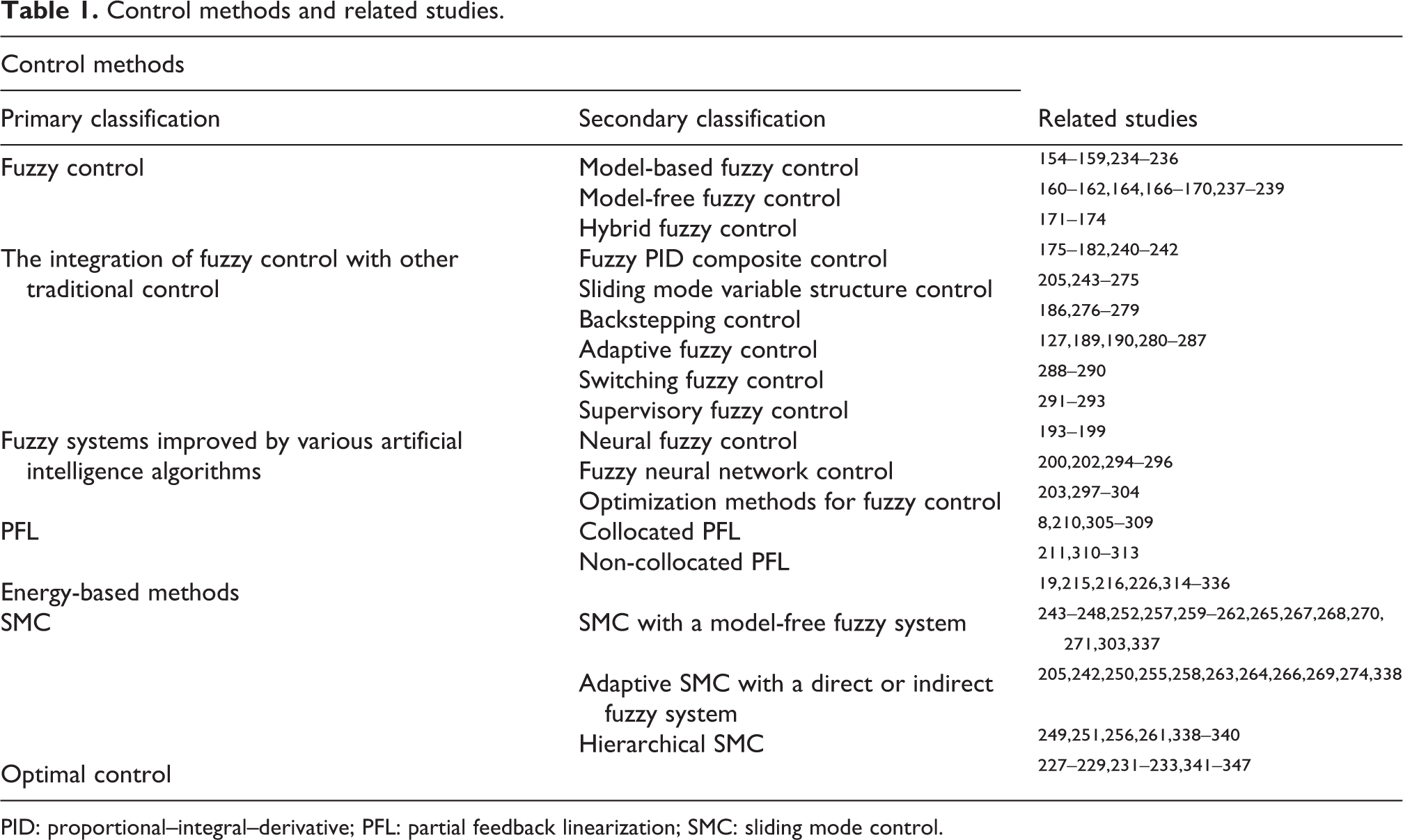
PID: proportional–integral–derivative; PFL: partial feedback linearization; SMC: sliding mode control.
Difficulties of UR
Highly nonlinear features and reduction of input space size are challenges for controlling UR. Design control methods are used to accommodate nonlinearity or reduce system order to low-dimension models. However, only some methods are applicable as a result of the limitation of the system. This section reviews these problems from the perspective of theoretical and realistic difficulties.
Theoretical difficulties
Controllability and stability
UR is a class of strong nonlinear systems, whose research focused on its complex dynamics, non-holonomic constraints, and lack of feedback linearization, while classical linear control theory is not applicable. Despite people have a good understanding of the dynamics of UR, there is increasing interest in their controllability.
Configuration features
A noteworthy work by Olfati-Saber, 210 he proposed an explicit coordinate change that converts several types of UR into cascaded nonlinear systems with structural properties. The advantage of this work is that the UR could be explicitly converted into a rigorous feedback form, a feedforward form, and a nontriangular linear/quadratic form on the basis of its structural characteristics. Then, the associated control methods could be easily applied.
Practical difficulties
Industrial problems
Now, UR is widely used in aerospace and industrial exploration and manufacturing. Examples of such systems include ships, underwater vehicles, helicopters, aircraft, satellites, and space platforms. Despite the success of these cases in a well-structured environment, their complex uncertainty control technology environment is still immature. 348,349 Nevertheless, an expectation exists for superior applications of UR that need to operate autonomously in an unstructured and potentially dynamical changing environment. 350 Therefore, control technologies to meet the requirements are critical.
High DOF composite UR problems
The benefits of UR could reduce weight, cost, and energy consumption while maintaining sufficient flexibility without losing access to the available configuration space. They are not damaged when striking objects and withstanding actuator failures better. As the DOF of UR increases, the reliability of the system decreases, which could lead to the practical problems in the control system.
Fault-tolerant detection and control problems
Actuator failures may result in a reduction in the number of control inputs that convert a fully driven robotic system into a UR system 351 or a robotic system with more control inputs to a robotic system with fewer control inputs. Sensor failures cause feedback signals to be delayed or lost, affecting the overall tracking performance of the system. Therefore, scientists and engineers in robot system design should consider both types of faults. It is highly recommended to use fault detection mechanisms. 352
Networked UR systems problems
Another practical problem is the network control of UR systems. Once introduced into the network, the communication between the actuators and the sensors may be interrupted, and the delay or loss of communication packets may result in poor control performance. Control of UR systems should be robust for network delays and require network control techniques (e.g. predictive control).
Conclusions and future research
UR system is an indispensable mechanical system for various engineering applications. Control of UR system is one of the important research directions in the field of control. For such a complex and extensive field, all the researches on UR systems are difficult to explain clearly in a review article. Nevertheless, this article could provide readers with the latest knowledge in the field of UR. At the end of the article, several important issues and possible future research directions are put forward. In summary, the research on UR has achieved certain results in the field of underactuated mechanisms, model establishment, and control system and applications. But there are still many problems to be solved: Underactuated mechanisms. Underactuated mechanism is the core of UR. It could be discretized into an underactuated rigid robot with a passive joint when studying a flexible robot. At present, research on URs with flexible rods or flexible joints is still rare. And the combination of underactuated characteristics and flexible robots may give full play to the advantages of both. Underactuated control system. It is necessary to continue to find and explore the control method suitable for the characteristics of the UR. The ability of single robot to cope with complex working environments is limited. Thus, the multi-robot coordination would be future development trend. Applications. UR could be used to many situations for its lightweight and flexible features, such as underactuated medical robotics, booster robotics, aerospace robotics, and unmanned system.
Footnotes
Declaration of conflicting interests
The author(s) declared no potential conflicts of interest with respect to the research, authorship, and/or publication of this article.
Funding
The author(s) disclosed receipt of the following financial support for the research, authorship, and/or publication of this article: This research was supported by the National Natural Science Foundation of China (no. 51675319).