
Abstract
Jellyfish uses jet propulsion to achieve a diversity of propulsion modes in the water. In this article, a miniature jellyfish-inspired swimming robot is designed and built, which is capable of executing horizontal and vertical propulsion and maneuvers. In order to imitate the jellyfish in terms of morphology and kinematics, the robotic jellyfish is designed to be comprised of a streamlined head, a cavity shell, four separate drive units with bevel gears, and a soft outer skin encasing the drive units. A combination of four six-bar linkage mechanisms that are centrally symmetric is adopted as the driver to regulate the phases of contraction and relaxation of the bell-shaped body. Furthermore, a triangle wave generator is incorporated to generate rhythmic drive signals, which is implemented on the microcontroller. Through independent and coordinated control of the four drive units, the robotic jellyfish is able to replicate various propulsion modes similar to real jellyfish. Aquatic tests on the actual robot verify the effectiveness of the formed design scheme along with the proposed control methods.
Introduction
Recent years have witnessed the rapid development of bioinspired robots that use creatures as a source of inspiration. 1 Among underwater robots, swimming robots have significant potential for study of marine life, monitoring oceanic environments, and underwater operations. 2 –7 As a specific sea creature, jellyfish has a soft body, which is found in the waters all over the world. Owing to low metabolic rate, jellyfish has the ability to move vertically without expending much energy, while it passively depends on ocean current, tides, and wind for horizontal movements. Therefore, the movements of bell-shaped jellyfish have provided researchers with a new understanding of jet propulsion. Furthermore, researchers have created bioinspired robotic jellyfish with flexible bells, which may lead to better underwater vehicles. 8 –10 For example, self-powering, autonomous robotic jellyfish will be used for underwater surveillance, biological observations, as well as military purposes.
To date, the majority of bioinspired swimming robots has been concentrated on fish which use body and/or caudal fin mode or median and/or paired fin mode to locomote in varying fluid environments. 11 However, there has been little research into flow ejected from volumetric contraction, that is, jet propulsion. The movement patterns of jellyfish, in general, can be divided into two distinct phases: contraction and relaxation phases. Shrinking the ringent cavity at the back makes the water inside jet back during the contraction phase, thus producing a reactive propulsion which becomes the main thrust source leading to locomote. 12,13 In order to realize jellyfish-like morphology and kinematics, different kinds of actuators have been investigated. Typically, traditional actuators and multiple motors are used to fabricate robotic jellyfish. Meanwhile, smart actuators are increasingly employed to mimic built-in compliance in jellyfish body, including shape memory alloys, 14 ionic polymer metal composites, 15 ionic conducting polymer films, 16 and dielectric elastomer actuator. 17 These smart actuators bring some advantages to the robotic jellyfish, involving small volume, reduced size, attenuated weight, and quiet locomotion. However, as opposed to other robot types and aquatic creatures, robots using smart actuators are excessively slow in speed, and generally slower than motor-propelled robots. 18 Moreover, some smart actuator-based robotic jellyfish are unable to execute 3-D free-swimming motion because they generate small propulsion force and encounter interference from the power supply wires.
In this article, the objective is to design and implement a miniature, mechanically driven robotic jellyfish, on the basis of the previous work on jet propulsion. 19 More specifically, a six-bar linkage-centered drive mechanism in conjunction with fine-tuned motion control leads to jet-propelled swimming similar to real jellyfish. With the embedded Advanced RISC Machine (ARM) controller, gyroscope, and lithium battery pack, the robot is a self-propelled and self-contained system. Both vertical and horizontal movements can be wirelessly adjusted by a triangular wave control algorithm. The latest results show that the robotic jellyfish attained a maximum horizontal swimming speed of 92.5 mm s−1, an average turning rate of 9° s−1, as well as a maximum vertical speed of 10 mm s−1, suggesting a relatively high likelihood of achieving both horizontal and vertical movements on the same robotic platform. More importantly, these obtained results offer an alternative to the development of large-scale jellyfish robot with hybrid movements.
The remainder of the article is organized as follows. The developed robotic jellyfish prototype is briefly introduced in section “Prototype of the self-propelled robotic jellyfish.” The motion control method and dynamic analysis are detailed in section “Motion control and dynamic analysis.” Results from aquatic experiments are provided in section “Experiments and results.” Finally, section “Conclusion” concludes the article with an outline of future work.
Prototype of the self-propelled robotic jellyfish
In this section, a brief overview of the built miniature self-propelled robotic jellyfish will be presented, followed by the system framework used for real-time jellyfish-like swimming.
Mechanical design
With inspiration from Aequorea victoria, as depicted in Figure 1, a scheme mainly involving four six-bar linkage mechanisms is proposed to replicate jellyfish’s movements based on ejection of water. Mechanically, the robotic jellyfish is composed of a streamlined head, a cavity shell (body), four separate drive units, and a soft outer skin encasing the drive units. More specifically, a six-bar linkage-based drive unit is illustrated in Figure 2. The driving force generated by servo is transmitted through the drive mechanism, and a pair of bevel gears is utilized to convert the direction of the rotational motion of the servo. An output shaft is set across a gear box which is also assembled to the lower shell of the body. A bearing with a lip-type packing is further set between the gearbox and the output shaft for waterproof purpose. Thus, the driving force is transferred to the six-bar linkage mechanism via the rocker. In particular, the travel distance from the rocker to bar 3 is amplified to better suit the deformation of the bell body. Interested readers can refer to the work done by Xiao et al. 19 for detailed dimension and kinematics of the six-bar leg mechanism. A combination of four leg mechanisms that are symmetrically mounted serves as the driver, which can be controlled separately or coordinately. 19
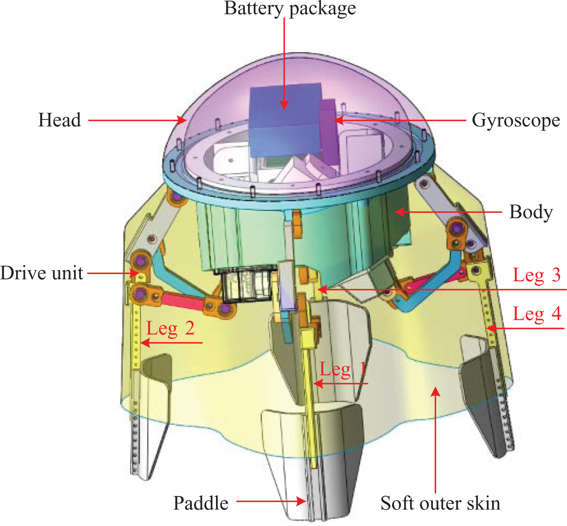
Mechanical configuration of the robotic jellyfish.
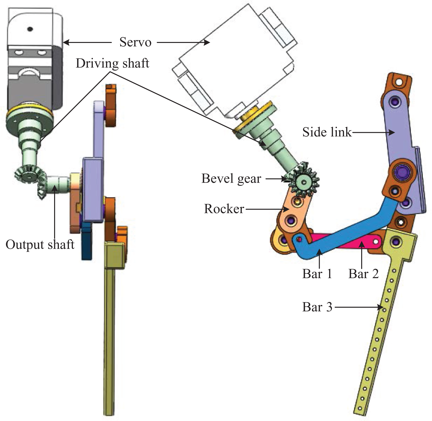
Schematic drawing of the crucial drive unit based on the six-bar linkage mechanism.
Considering the factors related to the buoyancy and gravity, except for the drive units, the rigid head and the hollow body made of acrylonitrile butadiene styrene are fabricated using 3-D printing. A soft outer skin is enwrapped around the drive units. Through squeezing water in and out of the bell, the robotic jellyfish is able to thrust itself upward or downward in the water. In particular, to strength the interaction force between the actuators and the drive units, paddles are devised to attach to the end of bar 3. The detailed technical specifications of the self-propelled robotic jellyfish are tabulated in Table 1.
Technical specifications of the developed robotic jellyfish.
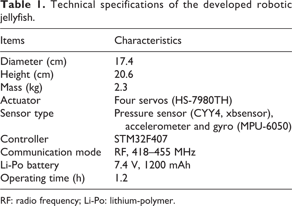
RF: radio frequency; Li-Po: lithium-polymer.
Control system framework
In order to generate jellyfish-like jet propulsion, a hybrid embedded control system framework is proposed. As shown in Figure 3, PC is used as the host which is responsible for remote control and monitor of the robotic jellyfish. At the client level, a hybrid control system with embedded microcontroller STMicroelectronics STM32F407 (Switzerland) is developed. It is responsible for signal and information processing, swimming control, and communication with the PC host. Note that the swimming control of the self-propelled robotic jellyfish is implemented in the STM32F407 through building a triangle wave generator.

Control system framework of the self-propelled robotic jellyfish.
Specifically, the communication unit wirelessly receives control commands from the upper controller and transmits data to the upper controller via Universal Synchronous/Asynchronous Receiver/Transmitter (USART). Then, the lower controller analyzes the commands and behaves accordingly. RF200 is utilized as the wireless communication module in that it permits setting up multiple channels of communication with high step precision, high transmitting power, and yet low power consumption. A gyroscope is incorporated into the control system, serving the purpose of capturing the robotic jellyfish’s attitude and transmitting it to the main microcontroller via USART. As a consequence, a feedback loop can be formed, serving to regulate the direction of the jellyfish robot autonomously.
In the part of software design, an upper PC-oriented console is built based on the design pattern of .Net. Functionally, .Net is responsible for communication, sensor data display, and swimming control. That is, the control commands can be sent and the operating parameters can be checked on this console in a friendly manner. Two communication ports of the PC are occupied, serving as control command sending port and sensor data receiving port. After effective analysis of data from gyroscope, actual angle of pitch, roll, and deflection can be displayed on the control panel, and refinements can be accomplished through buttons on the panel to control the attitude sensor. Speed control, motion mode switch, and options for relative equilibrium position, oscillatory amplitude, and the speed ratio of expansion of four actuators of the robotic jellyfish can be set through control parameter setting buttons. For the robotic jellyfish, an embedded software system is established and a data communication protocol is developed to guarantee a stable data link between the PC and the robot.
Motion control and dynamic analysis
In this section, the proposal of the triangle wave generator-based motion control method, dynamic analysis, and simulation results will be detailed.
Motion control
Regarding the locomotion of living jellyfish, McHenry and Jed explored how the size, shape, and behavior pattern of the jellyfish impacted its swimming speed and energy transformation. 20 In reality, the bell of the jellyfish enables it to control its vertical movements with ease. However, the jellyfish is not capable of any horizontal movement. For the robotic jellyfish, it is possible to change the attitude through barycenter adjustment. With the assumption of the robotic jellyfish being configured to be neutrally buoyant, both vertical and horizontal swimming modes can be easily accomplished. For the robotic jellyfish developed in this article, four legs actuated by servos can be independently controlled. Thereby, speed control can be achieved by modulating the oscillating frequency of the servos, while direction control is realized by offset control of the four servos in a coordinated way.
More specifically, the torsional angle of the output shaft of the servo is controlled by the duty ratio of the pulse-width modulation wave. A triangle wave of the duty ratio is then introduced to control the revolving of the servos. That is, the torsional angle of the output shaft varies in a triangular relation with respect to time. Let the movement direction of the legs in the relaxation phase be positive, conversely, the contraction phase be negative. Figure 4 gives a specific signal curve of the torsional angle of the servo, with a certain peak-to-peak value and frequency.

Illustration of control signal of the servo over one cycle.
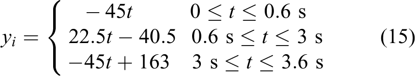
Mathematically, the triangle wave in one cycle is described as


where i = 1,2,3,4, yi is the torsional angle of the i-th servo, ki is the slope of the second line segment of signal of the i-th servo, αi is the ratio of slower phase speed and faster phase speed of the i-th servo, fi is the oscillation frequency of the i-th servo, ai is the oscillation amplitude of the i-th servo, t is the time, t1i is the time of trough of wave of the i-th servo, and t2i is the time of crest of wave of the i-th servo.
Among these parameters, ai, fi, αi, and ki are the key ones set in the control algorithm. They are also mutually constrained by equation (2). Considering the coherence and coordination of the four legs, the oscillation frequency of each leg remains the same, that is

Each corresponding part of the cycle of the four legs lasts an identical period


According to equations (5) to (9), it follows that

From equations (2), (7), and (10), it follows that

Notice that equation (11) is the main constraint condition that the four servos should follow. Thus, the relationship between the four servos’ torsional angles can be described as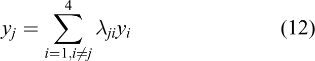
Furthermore, different sets of parameters lead to different motion modes. The ranges of the parameters α, ai, and ki in different motion modes are listed in Table 2. Undoubtedly ai and ki should accord with equation (11), and fi is derived from equation (2), having
Ranges of control parameters used in different motion modes.


Dynamic analysis
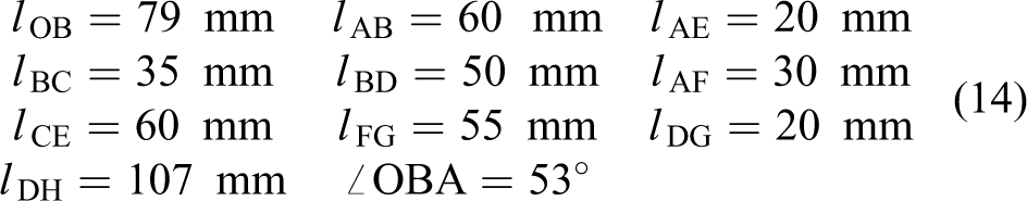
In order to facilitate the control analysis and performance estimation, as illustrated in Figure 5, a coordinate system for cavity section and six-bar linkage mechanisms is established. The mechanical characteristics in the coordinate system that matches the robotic prototype are listed as follows
Coordinate system of the robotic jellyfish cavity.
Then, the output curve of ∠PAF is plotted as Figure 6.
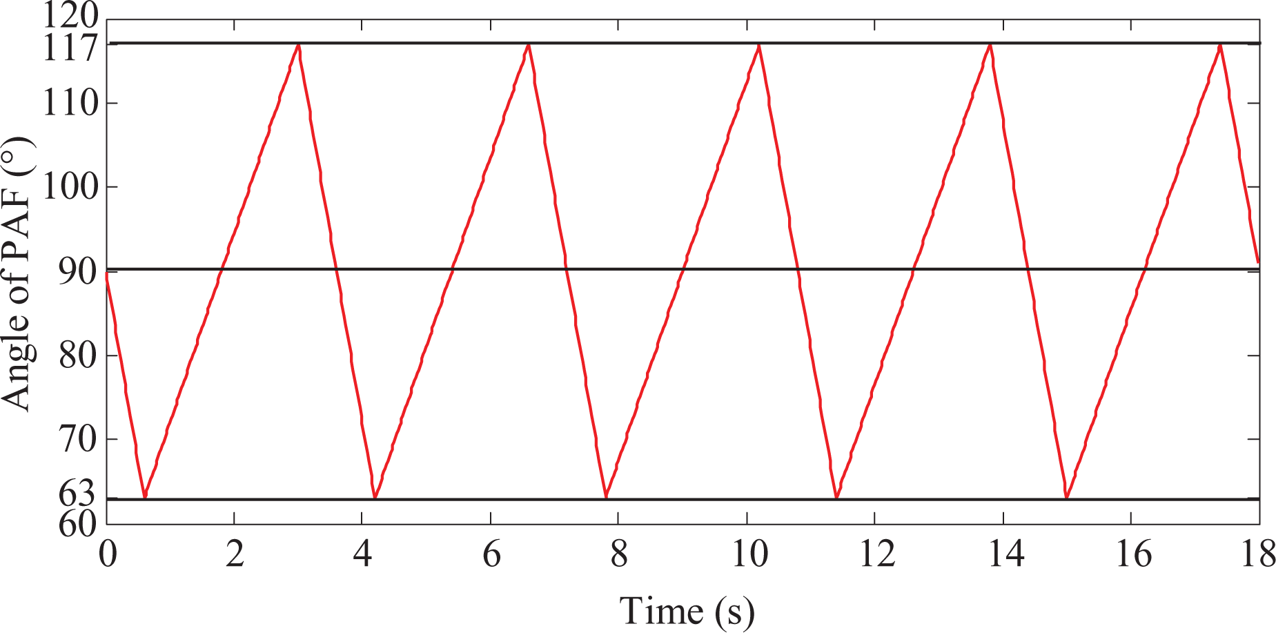
The output curve of ∠PAF.
1) The cavity volume change of the robotic jellyfish: As illustrated in Figure 6, the cavity volume can be easily derived with equation (16) once coordinates of point D and H are determined because the cavity volume is the sum of size of two frustum of a cone at any time.
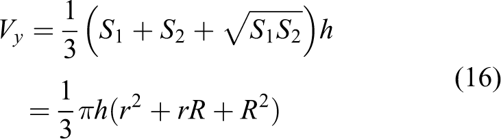
where S 1 and S 2 denote the area of upper and lower surfaces of the frustum of a cone, respectively; h is the height of the frustum of a cone; r and R are the radii of upper and lower surfaces of the frustum of a cone, respectively.
In practice, the coordinates of points D and H can be obtained through constant iterative computation by Cosine Rule, as depicted in Figure 7. The cavity volume and its change rate of the robotic jellyfish are shown in Figure 8. Remarkably, the volume change rate of the robotic jellyfish in the contraction phase is approximately 2000 cm3 s−1. Although the outer skin of the robotic jellyfish will actually wrinkle, causing that real volume change rate is less than the theoretical value, the thrust generated by squeezing water with such speed is sufficient to make the robotic jellyfish swim forward.

Moving trajectories of (a) D and (b) H.
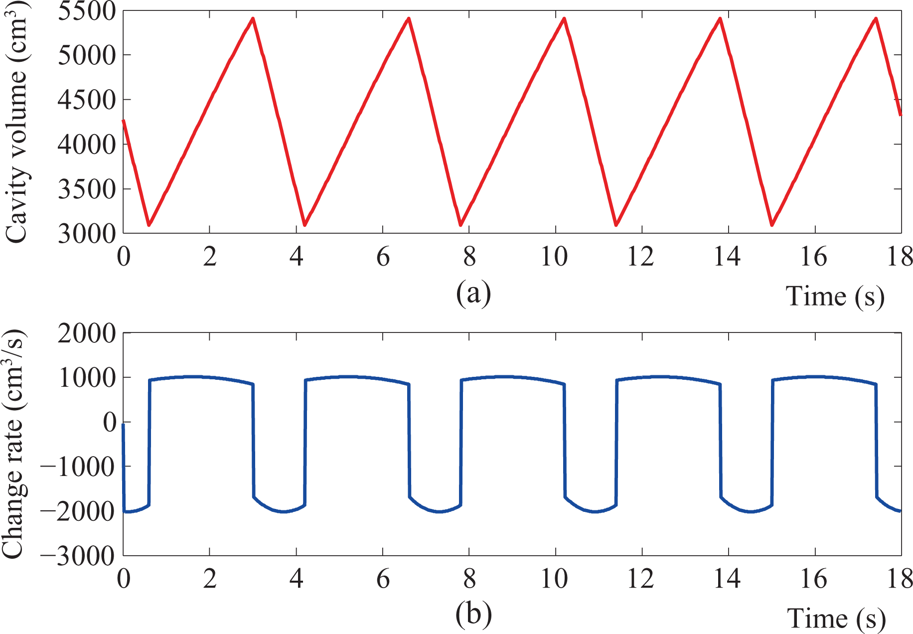
Illustration of (a) cavity volume and (b) change rate of cavity volume for the robotic jellyfish.
2) The jet thrust analysis of the robotic jellyfish: Water column jetted from cavity of the robotic jellyfish in time of dt is studied as research object with the infinitesimal method. According to the theorem of momentum, it follows that

where F indicates the force applying the water column jetted, dm is the mass of the water column jetted, and v is the speed of the water column jetted.

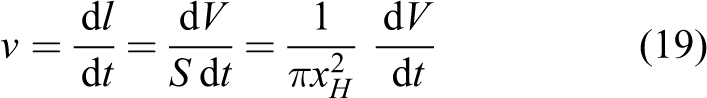
where ρ = 1000 kg m−3 is the density of water, dV is the volume of the water column jetted, and
By substituting equations (18) and (19) in equation (17), it is then easily derived that

According to Newton’s third law of motion, the thrust of the robotic jellyfish is

Consequently, the value of thrust in every moment can be computed. It is clear that the thrust is proportional to the square of the change rate of cavity volume. Particularly, the volume change rate in the contraction phase is about twice in the relaxation phase in accordance with Figure 8. It follows that the thrust generated in the contraction phase is about four times that in the relaxation phase. Considering that the time of the relaxation phase doubles the relaxation phase, the robotic jellyfish can obtain forward acceleration over a vibration period, although water drawn into cavity of the body in the expansion phase will produce force in the opposite direction against forward swimming of the robotic jellyfish. Therefore, the alternating acceleration in longitudinal direction is the cause of intermittent motion of the robotic jellyfish. It is noted that quantitative simulation analysis of jet propulsion will not be provided due to the space limitation. Please refer to the research by Li and Yu 21 for similar simulation analysis.
Experiments and results
To test and verify the proposed mechatronic design and control methods, aquatic experiments on the actual robotic jellyfish were conducted in a water tank with the dimensions 180 cm long, 100 cm wide, and 65 cm deep. Unless otherwise specified, the data points and error bars in subsequent figures were the averages and standard deviations of three runs aided by video analysis.
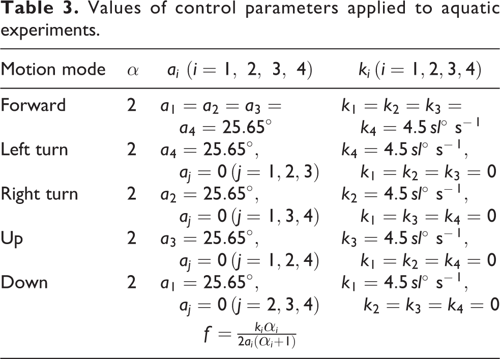
At present, a series of basic movements were tested, involving forward swimming, turning, and diving/surfacing. Specifically, the forward swimming mode depends on both the jet propulsion and the paddle mode, while the implementation of turning and diving/surfacing merely utilizes the paddle mode. It should be noted that there are some differences between turning movements and diving/surfacing movements during horizontal propulsion. The paddle mode for turning movements corresponds to a rotational torque around the action line of gravity, yet torque generated by paddle mode for diving/surfacing movements does not produce the rotational motion in that rotation causes a reverse gravity and buoyancy to prevent rotation torque, thus yielding oblique upward or downward movements. As also observed from Table 2, there is an overlap between the model parameters of turning and diving/surfacing movement, which theoretically interprets the diversity of movements. Of course, a specific set of control parameters should be configured to verify different propulsion modes. According to the slowest speed of rotation of the steering gear (4.5° s−1), another control parameter, speed level sl, is imported to characterize the pace of vibration of the actuators of the robotic jellyfish in subsequent analyses. Large speed level indicates the fast vibration speed and vice versa. With this denotation, sl can further be viewed as a variable on the control console.

Motion in vertical state
The vertical propulsion was first examined, in which the robotic jellyfish was configured as a vertical state. That is, the barycenter and the buoyant center were both in the central axis of the robotic jellyfish and the buoyant center was above the barycenter. Because the gravity was slightly greater than the buoyancy, the robotic jellyfish could sink into the bottom of water freely, where the direction of the head is approximately perpendicular to the water surface. The applied control parameters for motions in vertical state are listed as

where i = 1, 2, 3, 4. Note that sl can be changed through receiving command from the upper control console wirelessly. Similarly, ki and fi can alter freely. It holds that sl = 10 in this experiment.
The displacement and speed of an upward swimming are plotted in Figure 9. During data analyses, the average speed for each 0.1 s was calculated first. Then, 10 times polynomial interpolation was exploited to get a smooth speed curve. As can be clearly observed, the speed alters up and down intermittently. The fundamental reason is that jet propulsion mode has two phases, the contraction phase and the relaxation phase. The contraction phase generates the thrust to push the robotic jellyfish to accelerate, whereas the robotic jellyfish decelerates under the combined action of the fluid resistance and gravity in the relaxation phase.

Illustration of (a) displacement and (b) speed of the robotic jellyfish in an upward swimming.
Motion in horizontal state
Besides vertical propulsion, the horizontal propulsion ability of the robotic jellyfish was tested through adjusting the position of balancing weight. During horizontal swimming tests, the direction of the head is roughly parallel to the water surface. Similar to the tests of vertical propulsion, characteristic parameters for swimming forward, turning, and diving/surfacing modes in the horizontal state are tabulated in Table 3. Note that these parameters are empirically sought through trial and error and that some optimization or learning methods will be tried to speed up the turning process so as to optimize the robot speed and energy consumption.
Values of control parameters applied to aquatic experiments.
Swimming forward motion: Under different speed levels, speeds of forward swimming were measured. The relationship between forward swimming speed and oscillation frequency is depicted in Figure 10. As can be observed, the relationship between the swimming speed and the oscillation frequency is nonlinear. The robotic jellyfish reached a maximum velocity of 92.5 mm s−1 (corresponding to length-specific 0.45 body lengths s−1) at an intermediate frequency of 0.94 Hz. There are two possible reasons for this phenomenon. On the one hand, differential pressure resistance acting on the object in fluids is proportional to square of the speed, therefore higher oscillation frequency may incur larger drag other than thrust in water. On the other hand, the adopted servos for actuation may fail to respond to the control commands at high frequencies due to the limitations of inherent performance.
Turning motion: Similar to the forward swimming, turning motions were tested under different speed levels. Here, only turning right was demonstrated because of similarity. Figure 11 plots the relationship between turning rate and oscillation frequency, where only leg 2 moved during right turns. As expected, a nonlinear relationship exists between the turning rate and oscillation frequency. A maximum average turning rate of 9° s−1 also occurred at an intermediate frequency of about 0.6 Hz.
Diving/surfacing motion: Furthermore, the possibility of diving and surfacing using one leg was examined. During tests, the robotic jellyfish performed diving/surfacing motion while laying down on its side. That is, only leg 1 was used when diving and leg 3 when surfacing. Control parameter configuration is shown in Table 3. A snapshot sequence of continuous surfacing and diving is given in Figure 12(a). Apparently, the surfacing mode switched to the diving mode at approximately t = 24 s, where the head of the robotic jellyfish touched the water surface. Figure 12(b) further plots the relative height of the robotic jellyfish over time. As can be estimated from Figure 12(b), the up-and-down speed is about 10 mm s−1 (corresponding to 0.05 body lengths s−1). The overall swimming performance achieved by the robotic jellyfish, of course, should be significantly elevated when compared to its biological counterpart.

Relationship between forward swimming speed and oscillation frequency.

Relationship between turning rate and oscillation frequency.
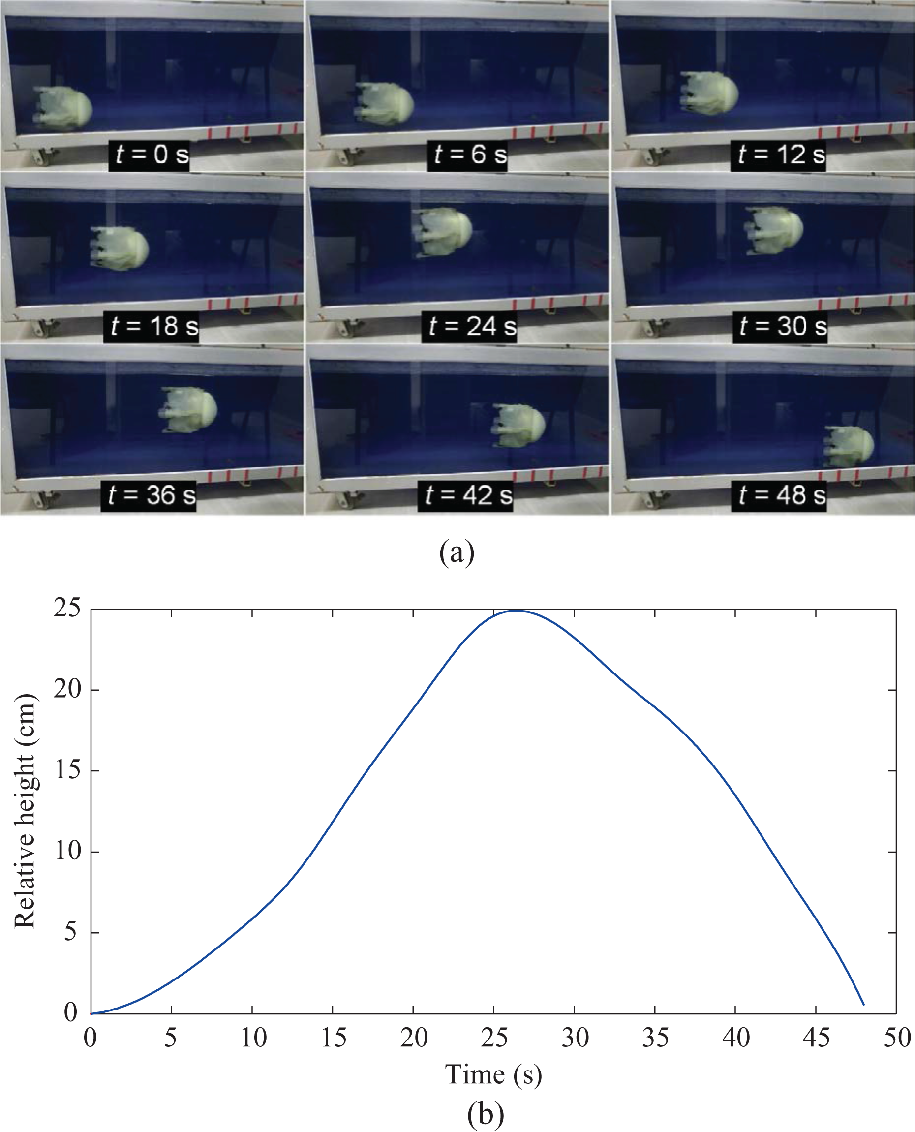
(a) Snapshot sequence of surfacing/diving and (b) its relative height over time in diving/surfacing.
As a result, tests conducted indicated that the design scheme mainly involving a six-bar linkage-centered drive mechanism and fine-tuned motion control is well suited to mimicry of jellyfish-like swimming. More remarkably, both vertical and horizontal movements can be implemented on the same robotic platform. Usually, the natural jellyfish is not capable of any horizontal movements. For that, it depends on the tides and the winds at the water surface. However, as for the robotic jellyfish, it is possible to switch between the vertical state and the horizontal state by barycenter adjustment. In addition, the use of soft and deformable materials in robotic jellyfish development is crucial to adapting to uncertain task and environments in the context of soft robotics. 22 –24 Thereby, further insight can be gained by partly or wholly incorporating compliance into robotic jellyfish development for improved propulsion performance.
Conclusion
This article presents a design for a miniature, self-propelled robotic jellyfish, mainly relying upon a six-bar linkage-centered drive mechanism and a fine-tuned motion control. More specifically, a synthesized system framework used for real-time jellyfish-like swimming is first proposed and built. Next, motion control methods in conjunction with simplified dynamic analyses are implemented to achieve diverse motion modes. Finally, preliminary test results on vertical and horizontal propulsion verify the effectiveness of the presented design scheme and control methods. More important for practical applications is the possibility of both vertical and horizontal propulsion on the same robotic jellyfish platform.
Future work will concentrate on enhancing the robotic jellyfish’s maneuverability by taking full advantage of barycenter adjustment in an intelligent fashion. In the long run, for the purpose of building a long-term mobile aquatic platform, more practical aspects of jellyfish robots including learning control and energy optimization (e.g. the study by Yu et al. 25 and Li et al. 26 ) should be taken into consideration, which may produce better bioinspired underwater vehicles and promising applications.
Footnotes
Declaration of conflicting interests
The author(s) declared no potential conflicts of interest with respect to the research, authorship, and/or publication of this article.
Funding
The author(s) disclosed receipt of the following financial support for the research, authorship, and/or publication of this article: This work was supported in part by the National Science Foundation of China (61375102, 61333016, 61633020, and 61573226), the Beijing Natural Science Foundation (4161002), the National Defense Science and Technology Innovation Fund of Chinese Academy of Sciences (CXJJ-16M110), and the State Key Laboratory of Alternate Electrical Power System with Renewable Energy Sources under grant LAPS16006.