
Abstract
In this work, the influence of the cobalt phase on the growth of carbon nanotubes by the catalytic chemical vapour deposition of CH4 with catalysts containing Co, Mo and Mg is investigated. To this end, the catalytic behaviour of physically mixed CoO/MgO+MgMoO4 and CoMoO4+MgMoO4 is studied. The results obtained show that CoMoO4+MgMoO4 allows for the attainment of the highest CNT yield (2407 wt % against 1296 wt %). Its higher activity is ascribed to the greater formation of active sites that, in light of current assessments, are constituted by metallic cobalt adjacent to Mo2C, and the huge exfoliation of the catalyst, which contributes towards enhancing their exposure.
1. Introduction
Carbon nanotubes (CNTs) are unique tubular structures of nanometre diameter and with a large length/diameter ratio. CNTs can consist of one rolled shell of sp2 carbon (single wall carbon nanotubes - SWCNTs) and up to several tens of coaxial shells of carbon (multi wall carbon nanotubes - MWCNTs) with an adjacent shell separation of 0.34 nm. The carbon network of the shells is closely related to the honeycomb arrangement of the carbon atoms in the graphite sheets. Due to their quasi-one-dimensional structure and the graphite-like arrangement of the carbon atoms in the shells, CNTs possess unique mechanical [1], thermal [2] and electrical properties [3], representing a key material for applications in a wide range, including electronics [4], sensors [5,6], energy production devices [7,8], structural materials [9], fillers [10,11], adsorbents and catalysts [12,13].
A measure of the great interest shown towards the application of CNTs for the development of new technologies and materials is given by data on their industrial production available in the Panel Report on the “International Assessment of Research and Development of Carbon Nanotube Manufacturing and Applications” by the World Technology Evaluation Centre (WTEC) [14]. The production capacity of both MWCNTs and SWCNTs currently appears to be dominated by Asian countries (Japan, China and South Korea). However, European manufacturers such, as Germany's Bayer, France's Arkema and Belgium's Nanocyl, are looking to increase their competitiveness and boost their production capacity [15].
Many of the processes employed for CNT industrial production see catalytic chemical vapour deposition (CCVD) as the primary growth technique. This process, mainly stemming from academic studies, usually includes a transition metal (such as Fe, Co or Ni) and hydrocarbon or CO, has been recognized as the most practical synthetic method, with low costs and high yields [16].
To date, the literature data prove that two processes exhibit the highest yields of CNTs: a) the CCVD of camphor over zeolite-supported Fe-Co, which allows the production of 1,000 wt% of CNTs with respect to the catalyst mass [17,18], and b) the CCVD of CH4 over MeMo-Mg catalysts (where Me = Co or Ni) with a Mo:Me molar ratio 30:1 [19–22], prepared by the sol-gel method proposed by Ning et al. [20]. In this pioneering work, a CNT yield of 1,500 wt% is reported. As widely accepted, copious CNT growth requires the co-presence of all the three metallic components, and the MgMoO4 phase plays a dominant role in the CNTs' production, helping with the dispersion of the active Co nanoparticles following the decomposition of the CoO present in the catalyst [21].
In the present work, we demonstrate that in order to obtain mass-CNT production the crystalline phase of Co also matters. In particular, cobalt in the form of CoMoO4, present together with MgMoO4 allows for the best results. To achieve this goal, the catalytic behaviour of physically-mixed catalysts of CoO/MgO+MgMoO4 and CoMoO4+MgMoO4 was investigated.
2. Experimental Section
2.1 Catalysts preparation
Bi-metallic cobalt-molybdenum, cobalt-magnesium and magnesium-molybdenum catalysts were synthesized by the sol–gel method according to the procedure reported elsewhere [20]. Basically, metal nitrate precursors Mg(NO3)2·6H2O (Mg = 12 mmol) and/or Co(NO3)2·6H2O (Co = 1 mmol) were mixed in a citric acid solution (3 g of citric acid in 10 mL of H2O) and stirred until complete dilution was achieved. The solution was dried at 393 K into a foamy paste and then, in the case of catalysts containing molybdenum, was mixed with molybdenum powder (Mo = 31 mmol). All the catalysts were calcined in static air at 1023 K for 5 h. Codes are reported in Table 1.
The catalyst codes B and PM stand for ‘bimetallic catalyst’ and ‘physical mixture’, respectively; Co-Mo-Mg stands for ‘tri-metallic catalyst directly prepared by the sol-gel method’. The cobalt and molybdenum contents, as inferred by ICP-MS, refers to catalysts pre-heated up to 1173 K under He flow. YC (%), calculated as 100*mC/mCo, where mC is the mass of carbon and mCo is the mass of cobalt, represents the specific carbon yield. G/D and ΓD represent the average values of the G to D band intensity ratio and the FWHM of the D-band.

Reproducibility ± 10%
PM1 is the physical mixture of BCo-Mg and BMo-Mg
PM2 is the physical mixture of BCo-Mo and BMo-Mg
2.2 Carbon nanotube synthesis
The CNTs were grown in a quartz tube (diameter = 5 cm, length = 70 cm) placed in a horizontal furnace. The catalysts' masses (50 mg) were uniformly spread as a thin layer (l= 0.5 cm, w= 0.5 cm) in a quartz boat (l= 18 cm, w= 2 cm, h= 1.4 cm) and pre-heated up to the synthesis temperature (1173 K) under He flow (500 sccm) at a heating rate of 10 K/min. Helium was then replaced by the mixture of CH4 (1000 sccm) and H2 (30 sccm). The reaction was stopped after 30 min and the reactor was allowed to cool under He flow (500 sccm). Afterwards, the solid was collected from the quartz boat, weighed and characterized.
2.3 Characterization
XRD analysis was performed with an APD 2000 (Ital Structures) diffractometer using a CuKα radiation source. The patterns were recorded in step scan mode from 10° to 50° 2-theta angles (step of 0.02°, counting time of 1 sec/step).
Elemental analysis of the catalysts, previously digested with doubly distilled 2 % v/v HNO3, was carried out by means of inductively coupled plasma mass spectrometry-ICP-MS (Perkin Elmer NexION 300XX). Measurements were performed on 59Co and 98Mo isotopes.
The morphology of the catalysts and their selectivity towards the nanotubes were evaluated by SEM using a JEOL JSM 5600LV, operating at 20 kV. The dimensions and crystalline structures of the carbonaceous products were investigated by HRTEM utilizing a JEOL JEM 2010, operating at 200 kV and equipped with a Gatan 794 Multi-scan CCD camera.
The crystalline quality of the as-obtained CNTs was analysed by measuring the Raman scattering excited at 2.41 eV (514.5 nm). For this purpose, a Jobin Yvon Ramanor U-1000 double monochromator, equipped with an Olympus BX40 microscope was used together with a Hamamatsu R943-02 photomultiplier operating in photon-counting mode. Light was focused on the sample on a spot 2 μm in diameter through the X50 microscope objective lens. Spectra were independently acquired from ten random positions on each sample. An acquisition time of 30s was used to improve the signal-to-noise ratio.
The spectra were analysed using a commercially available spectroscopic analysis software package. Lorentzian bands, superimposed on a constant background, were used to reproduce the spectral profile. The G- and D-peak amplitudes, chosen by a least-square best-fit method, were used to calculate the intensity ratio G/D. The most representative parameters obtained as an average on ten measured values [23] are reported in Table 1.
3. Results and discussion
3.1 Catalysts' characterization
Figure 1 summarizes the results of the structural characterization by XRD on bi-metallic catalysts. It is worthwhile noticing that, in order to study the crystal structure of the catalysts “as seen” by the hydrocarbons, all the samples were analysed after the pre-heating step (see section 2.2).
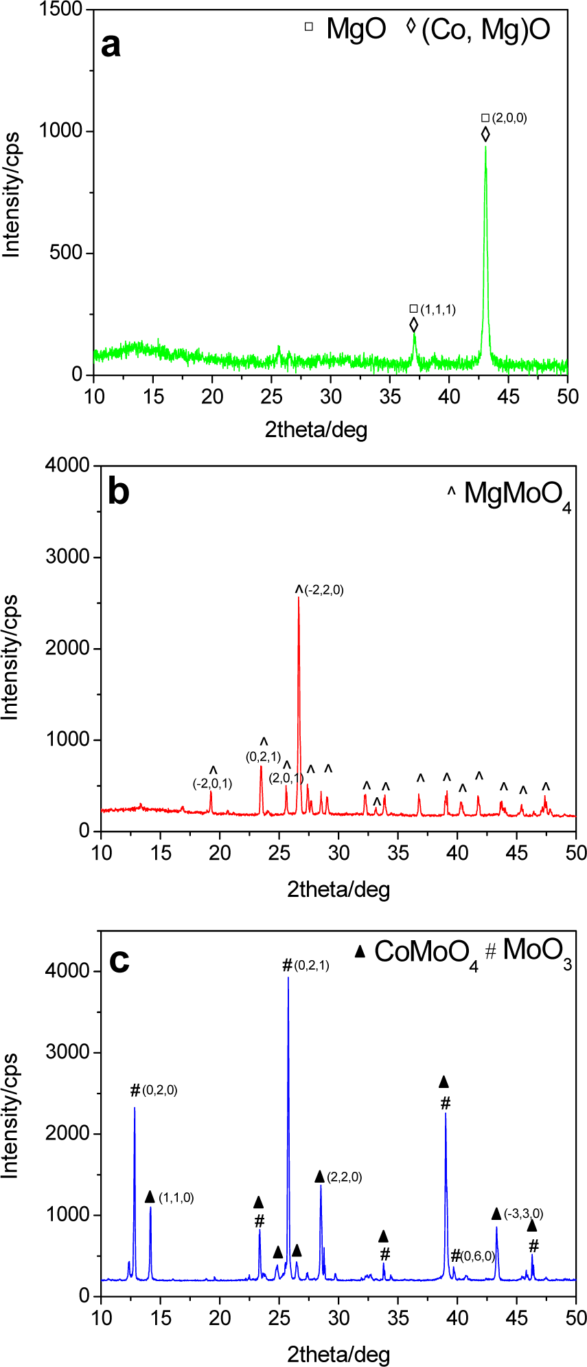
XRD patterns of the catalysts pre-heated in He up to 1173 K: BCo-Mg (a), BMo-Mg (b) and BCo-Mo (c). Miller indexes are also reported.
The XRD pattern of BCo-Mg (Figure 1a) mainly shows diffraction peaks due to cubic MgO (JCPDS card 43-1022). Nonetheless, and in agreement with previous findings [21], the presence of a Co-Mg oxide solid solution cannot be excluded as the corresponding diffraction peaks overlapped with those of MgO. The diffraction peaks detected for the BMo-Mg catalyst (Figure 1b) fully match with those of MgMoO4 (JCPDS card 21-0961). Although the Mo/Mg molar ratio used in the preparation (2.7) is higher than the stoichiometric ratio required for the formation of MgMoO4 (Mo/Mg = 1.0), no other crystallographic phase deriving from the excess of Mo is observed. In the case of the BCo-Mo catalyst (Figure 1c), intense diffraction peaks of the CoMoO4 phase (JCPDS card 25-134) are present together with those of MoO3 (JCPDS card 35-0609).
The cobalt and molybdenum contents of the catalysts, evaluated by means of ICP-MS, are reported in Table 1. The results reveal that while the amount of Co is very close to the initial amount (0.9 in place of 1.0 mmol), the Mo content dramatically diminishes in the case of the BCo-Mo (1.0 against 31.0 mmol) and BMo-Mg (16.0 against 31.0 mmol) catalysts. The decreasing percentage with respect to the initial amount is about 97% for BCo-Mo and 48% for BMo-Mg. This significant molybdenum loss, which might account for the absence of the diffraction peaks of the expected magnesium-free molybdenum phases in the case of BMo-Mg can be explained by considering the sublimation of the low-melting MoO3 (mp = 1068 K) upon heating at 1173 K, in agreement with previous findings [22]. Indeed, as soon as the reactor temperature reaches 1073 K, the emission of yellow vapours is observed, which condense on the glass wall reactor outside the heater (at lower temperatures). Elemental analysis of the condensate collected in different regions confirms the presence of molybdenum.
3.2 CNT synthesis
Carrying out CCVD reaction on bi-metallic catalysts, no formation of carbon filaments (neither in the form of fibres nor CNTs) occurs, as clearly evidenced by SEM analysis (Figure 2a,c,d). The lower synthesis temperature adopted here (1173 against 1273 K) might be responsible for the apparent disagreement with the formation of carbon fibres reported by other authors in the case of cobalt-magnesium [21].

SEM micrographs and XRD patterns (insets) of the solid discharged from the reaction vessel after reaction with bimetallic catalysts. The SEM images refer to BMo-Mg (a), BCo-Mo (c) and BCo-Mg (d), respectively. The microstructure of BMo-Mg before reaction (b) is also shown.
After reaction with BMo-Mg the solid shows a platelet-like structure (Figure 2a) and XRD analysis (inset of Figure 2a) evidences the presence of MgO, MoO2 (JCPDS card 33-0929) and Mo2C (JCPDS card 35-0787). This result suggests that the MgMoO4 present at beginning of the reaction (Figure 1b) decomposes to MgO and MoO3; then, the latter is reduced by H2 to MoO2 and carburizes to hexagonal Mo2C in the presence of CH4 [24].
These modifications bring about a change in the morphology: the large-size non-porous structure of MgMoO4 (Figure 2b) transforms into smaller, thin sheets with a layered structure (Figure 2a). The morphology change can be rationalized in light of the chemical-structural modification of the solid. In particular, the strong expansion and shrinkage of the crystal lattice volume (CLV), occurring in the decomposition of MgMoO4 (CLV = 127.73 Å3) to MoO3 (CLV = 209.99 Å3) and MgO (CLV = 74.78 Å3), are responsible for the break of the MgMoO4 particles, in agreement with previous findings [25]. Moreover, the MoO3 reduction to MoO2 and the carburization to Mo2C causes a further CLV reduction in the molybdenum phase from 209.99 Å3 (MoO3) to 37.21 Å3 (Mo2C), giving rise to the formation of the layered structure of the hexagonal sheets.
After reaction, BCo-Mo appears as dispersed, rounded particles, with sizes ranging between 5 and 50 nm, and covered by a thin carbon layer (Figure 2c). XRD analysis reveals the presence of MoO2, Mo2C and metallic Co (inset of Figure 2c). A very broad peak at 2-theta = 19.4° is also present, compatible with the allotropic form of carbon known as ‘Chaoite’ [26].
Finally, as to BCo-Mg, its morphology does not change after reaction (Figure 2d) with respect to that of the pre-heated catalyst (not shown for reasons of brevity). In addition, the XRD pattern (inset of Figure 2d) matches with that shown in Figure 1a.
Different from the bi-metallic catalysts, physical mixtures (PMs) of BCo-Mg+BMo-Mg and BCo-Mo+2BMo-Mg (below labelled ‘PM1’ and ‘PM2’), along with the cobalt and molybdenum contents reported in Table 1, give rise to the formation of carbon filaments (Figure 3a,b) with a tubular structure. (Figure 3e).

SEM micrographs of the products after reaction with PMs. Figures refer to: PM1 (a, c) and PM2 (b, d). HRTEM image (e) proves the tubular nature of the filaments.
Consistently, the typical fingerprint of CNTs (namely, the D-, G- and G'-bands) is detected in Raman spectra (Figure 4 a,b). The detection of a relatively intense G'-band proves the presence of long-range order in the graphene layers, while the G/D intensity ratios and 100/ΓD values, respectively, indicate a satisfactory degree of graphitization and the absence of amorphous carbon phases [11,16,23,27].

Raman spectra of nanotubes grown on PM1 (a), PM2 (b) and Co-Mo-Mg (c) catalysts
Between PMs, significant differences in specific carbon yield, calculated as YC (%) = 100*mC/mCo, where mC is the mass of carbon and mCo is the mass of cobalt, are observed (Table 1). A by far greater YC is achieved with PM2.
In both cases, XRD analysis (Figure 5) after reaction shows the typical diffraction peaks of graphitic carbon (at 2-theta = 26.3°), MgO and Mo2C. No diffraction peak of the Co phases is present, suggesting that cobalt is largely dispersed into the solid matrixes.
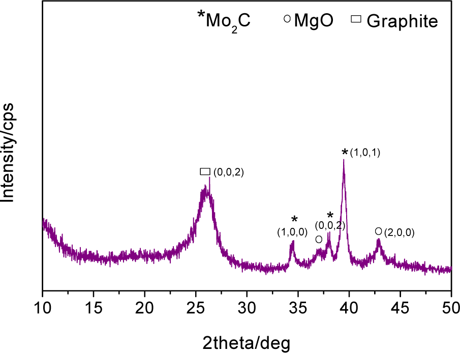
XRD patterns of the products after reaction with PMs. The case of PM1 is shown. Miller indexes are also reported.
SEM analysis of the products evidences that, in the case of PM1, the morphology of the solid consists of large particles entirely covered by short CNTs (Figure 3a,c); instead, PM2 gives rise to bundles of straight and longer CNTs connected by tiny catalyst particles and platelets (white and black arrows in Figure 3b, respectively) suggesting a two directional growth [28]. Moreover, the presence of CNT-free catalyst sheets (Figure 3d) evidences a large exfoliation.
From the above results, it is apparent that differences in CNT yield, morphology and crystalline quality between PM1 and PM2 arise from the cobalt phase present in the catalyst.
In light of current assessments, which see CNTs growing on Co sites adjacent to Mo2C [21,29], it is likely that in the case of PM2 the formation of active sites is largely favoured and, what is more, the significant exfoliation of the catalyst contributes towards enhancing their exposure.
Instead, when Co dispersed onto MgO is physically mixed with MgMoO4, as in the case of PM1, the growth of CNTs is hampered because of the reduced number of active sites and/or the lack of catalyst exfoliation.
3.3 Comparison of CNT morphologies synthesized with PMs and tri-metallic Co-Mo-Mg
Under the conditions of CCVD of the present work, the tri-metallic Co-Mo-Mg catalyst directly prepared by the sol-gel method reported in section 2.1 leads to a YC value of 2037%. It is worth noting that this value lies between the specific yields achieved with the two PMs (Table 1).
SEM analysis reveals that the CNTs are organized in two different ways: curly and short CNTs (black contours in Figure 6) coexist with straight and long filaments connected by catalyst particles and sheets (white arrows). These arrangements closely recall the CNT morphologies produced with PM1 (Figure 3a) and PM2 (Figure 3b), respectively.
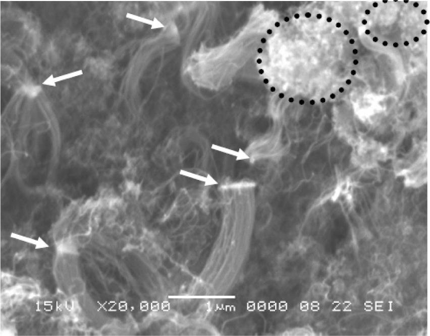
SEM micrograph of CNT obtained with a tri-metallic Co-Mo-Mg catalyst
The results achieved with the PMs allow for an understanding of the behaviour of the tri-metallic catalyst in terms of the specific yield and morphologies of the CNTs.
Entanglements of curly and short CNTs are thought of as extruded from the less-active catalyst region (labelled region 1) where Co, mainly distributed in the MgO, is in close contact with the MgMoO4 phase. Instead, long and straight CNTs are likely to form in the catalyst region (labelled region 2) where CoMoO4 in the vicinity of MgMoO4 is mainly present. The intermediate YC value obtained with the sol-gel catalyst is consistent with the co-presence in this catalyst of the two portions featured by different activity.
These evidences suggest that, in the case of the direct preparation of the tri-metallic catalyst, the search for proper preparation conditions which allow for the addressing of the prevailing formation of the phase CoMoO4 is mandatory in obtaining a highly efficient catalytic system.
4. Conclusion
The catalytic behaviour of physically mixed CoO/MgO+MgMoO4 and CoMoO4+MgMoO4 was studied in order to clarify the role played by the cobalt phase in the growth of carbon nanotubes by the catalytic chemical vapour deposition of CH4 with catalysts containing Co, Mo and Mg.
The results of the present study prove that catalyst portions where CoMoO4 is in the vicinity of MgMoO4 feature higher activity than those where the Co distributed in the MgO is in close contact with the MgMoO4 phase. These findings provide guidelines to follow in the direct preparation of the tri-metallic catalyst to improve its catalytic efficiency.
Footnotes
5. Acknowledgments
This research was supported financially by the Programma Operativo Nazionale Ricerca e Competitività “PON R&C” 2007–2013 (Nos. PON02_00153_2849085 and PON01_01869), granted by Ministero dell'Istruzione e della Ricerca Scientifica, Italy.