
Abstract
In this study, Fe/MgO catalysts with three different iron contents (5, 10, and 15 wt.%) were prepared by three catalyst preparation methods: impregnation, solution combustion synthesis, and co-calcination of metal nitrates. The resulting catalysts were subjected to methane at 900°C in order to grow carbon nanotubes (CNTs). The powders and products were then studied by X-ray diffraction (XRD), differential thermal analysis (DTA), scanning and transmission electron microscopy (SEM and TEM), and Raman spectroscopy. Formation of MgFe2O4 upon heating the catalysts to 900°C was confirmed by XRD. After the growth step, corresponding peaks of MgFe2O4 disappeared and metallic iron peaks appeared, indicating that MgFe2O4 is the responsible phase for production of iron nanoparticles. HRTEM images showed that the product on the 5 wt.% catalysts was mostly SWNTs and DWNTs with no evidence of carbon nanofibres or multi-walled carbon nanotubes on the co-calcination catalyst. Furthermore, ID/IG ratios obtained from Raman spectra were all below 0.1, except for one sample, showing the good quality of the products.
Keywords
1. Introduction
Due to their unique properties, single- and double-walled carbon nanotubes (CNTs) have found numerous applications in fields such as catalysis, composites, and electronics. However, commercialization requires large-scale and cost-effective synthesis processes. Catalytic chemical vapour deposition (CCVD) has become well-established as a very efficient technique in such processes [1, 2], which requires the presence of a catalyst.
Several methods for the preparation of the catalyst have been reported, as well as different ways to modify the synthesis of desired CNTs. Among them, impregnation is perhaps the most common. Using this method, Colomer et al.[3] reported the large-scale synthesis of SWNTs over Fe/MgO, Co/MgO, and Ni/MgO catalysts. Ago et al. [4] synthesized single-walled carbon nanotubes (SWNTs) and double-walled carbon nanotubes (DWNTs) over MgO-supported catalysts and reported that the catalytic activity of Fe was higher than with Ni and Co; this has been corroborated elsewhere [3, 5]. Ning et al. [6] synthesized SWNTs and DWNTs over heat-treated Fe/MgO catalysts and revealed that hydrogen treatment has a very detrimental effect on CNT quality. This adverse effect of hydrogen was also reported by Ago et al. [7], correlated to iron-particle coarsening during the H2 reduction process. Recently, the present authors reported successful synthesis of CNTs over Fe/MgAl2O4 catalysts through CCVD without using additional H2 [8]. Nie et al. [9] reported synthesis of very high-quality CNTs applying an ethanothermal process on impregnated Fe/MgO catalysts. Ghanbari et al. [10] significantly improved the quality of CNTs grown over Fe/Al2O3-SiO2 hybrid support using a unique N2 treatment process, and Palizdar et al. [11] synthesized CNTs over Fe/MgO catalysts prepared through calcination of aqueous metal nitrates solution.
A second common method, solution combustion synthesis (SCS), involves mixing desired ratios of metal nitrates (support and catalyst) with fuel and water, followed by subjecting the solution to heat [12]. SCS has proven to be a promising route towards achieving a homogenous and fine powder with high surface area, enabling the production of high-tech oxides and solid solutions [12, 13], especially catalysts for CNT synthesis by CCVD [14–16]. Using this method, Coquay et al. [17] prepared Fe/MgO catalysts followed by the growth of CNTs using a mixture of CH4 and H2. They reported carbon nanofibres (CNFs) and multi-walled nanotubes (MWNTs) as the by-products of the process.
A method of catalyst preparation which has remained less recognized is co-calcination (CC) of metal nitrates without using any extrinsic solvent like water or alcohol. This paper compares CC to the impregnation and SCS methods as a potentially much easier method for CNT synthesis over a catalyst. For this purpose, the support and catalyst precursors in the form of nitrates are mixed and heated abruptly. Thus, after dissociation of nitrates, oxides will be formed. The method is quite simple and quick, as it only entails mixing of the nitrates with desired ratios, followed by abrupt heating at proper calcination temperature. Since very few parameters are involved, reproducibility of the catalyst preparation step is guaranteed, i.e., unlike impregnation, it is not dependent on the pristine MgO morphology, and compared to SCS it consumes fewer materials and has lower costs. Among the surveyed literature, this method has only been used once for preparation of Fe/Al2O3 catalysts [18].
The aim of this study is to investigate the effect of different catalyst preparation methods and different iron contents on Fe/MgO catalyst powder and consequently on CNT product. For this purpose, three catalyst preparation methods were used, i.e., SCS, impregnation, and CC of metal nitrates. Each group included catalysts with 5, 10, and 15 wt. % iron content. Finally, the resulting catalyst and product were investigated by means of X-ray diffraction, differential thermal analysis, scanning electron microscopy, high-resolution transmission electron microscopy, and Raman spectroscopy.
2. Experimental Procedure
2.1 Preparation of catalyst powders
In a typical CC reaction, 0.36, 0.72, and 1.08 g of iron nitrate (Merck) was mixed with 6.43 g magnesium nitrate (Merck) to obtain 5, 10, and 15 wt.% Fe/MgO catalysts, respectively. The mixture was heated and stirred at 70°C for about 15 minutes in air until the nitrates formed a homogenous melt. Next, the solution was calcined in a muffle furnace preheated to 500°C over 30 minutes. The product was peeled off the vessel and ground with an agate mortar. The catalysts with 5, 10, and 15 wt.% Fe were designated CC5, CC10, and CC15, respectively.
As for the SCS method, according to Patil et al. [19], stoichiometric amounts of iron nitrate (Fe(NO3)3.9H2O, Merck), magnesium nitrate (Mg(NO3)2.6H2O, Merck), and urea (CH4N2O, Merck) were dissolved in 3 ml of distilled water. The amounts were mixed such as to obtain the desired weight percent of iron on 1 g MgO. The mixture was stirred and heated at nearly 50°C until a clear orange solution was obtained. Then, the solution, in a Pyrex vessel, was placed in a muffle furnace preheated to 600°C. After the combustion reaction was completed, the catalyst in the form of a crust was peeled off the vessel, ground with an agate mortar and calcined in air at 500°C for five hours. The 5, 10, and 15 wt.% Fe/MgO catalysts prepared by the SCS method were designated SCS5, SCS10, and SCS15, respectively.
For the impregnation method, 0.5 g of MgO powder was sonicated for 20 minutes in 30 ml of iron nitrate-ethanol (Merck) solution, and was then stirred at 65°C until the solvent evaporated. The obtained orange powder was ground by an agate mortar, dried at 110°C for 12 hours and calcined in air at 500°C for five hours. The 5, 10, and 15 wt. % Fe/MgO catalysts prepared by impregnation were designated IM5, IM10, and IM15, respectively.
2.2 Growth of CNTs
Catalyst powder (0.1 g) was loaded in an alumina boat and heated to 900°C with the heating rate of 15.5°C/min in a horizontal tube furnace housing a silica tube with a diameter of 5 cm under N2 gas flow (350 cm3/min, 99.99% purity). Next, nitrogen was switched to methane (6000 cm3/min, 99.995% purity) with the dwell time of five minutes. Next, the specimens were cooled under N2 with the same flow rate as the heating step and designated by adding NT to the code, e.g., NTCC15.
2.3 Characterization of catalyst powders and products
Characterization of different phases in catalyst powders was performed by X-ray diffraction (XRD, Philips-PW1800, Cu-kα, Ni monochromator). In order to prepare the catalyst powders for XRD just before passing methane, they were heated under N2 according to the growth heating programme without passing methane, followed by abrupt cooling. Differential thermal analysis (DTA, Shimadzu-DTA50, 10°C/min) was used to trace the phase evolution in catalysts. Morphological studies were performed using a scanning electron microscope (SEM, Wega II Tescan) and a transmission electron microscope (TEM, Philips-CM200FEG), and finally Raman spectroscopy (Almega Thermo Nicolet instrument working with 532-nm-wave-length Nd:YLF laser) was used to evaluate CNT quality. The ID/IG ratios were obtained by dividing the area under the D band by the area under the G band.
3. Results and Discussion
To find the proper calcination temperature, DTA was performed on the CC sample with 15 wt.% Fe after melting at 70°C in air. The traces in Fig. 1 show four distinct peaks; after 445°C no peaks could be found up to 900°C, indicating that the decomposition reaction was complete. Therefore, 500°C was chosen as the calcination temperature.
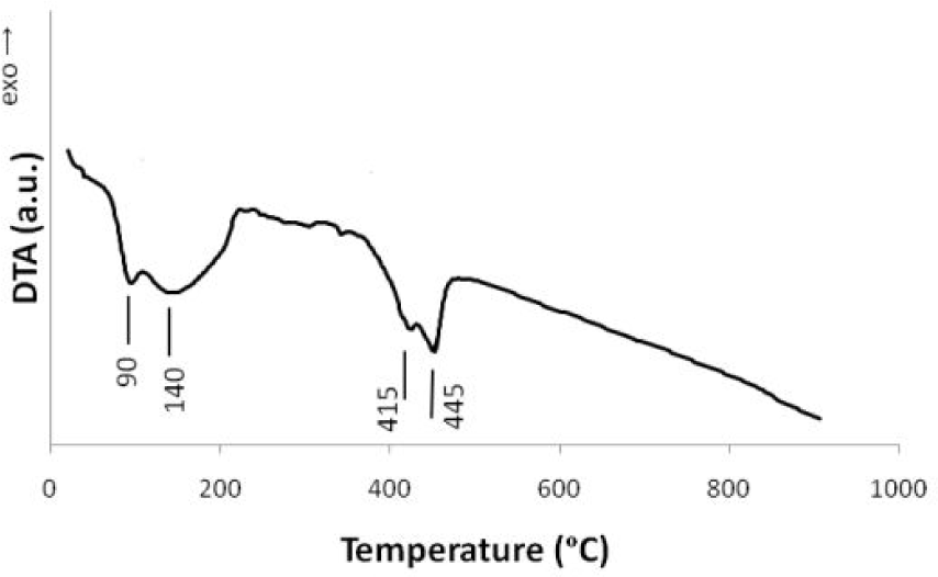
DTA traces of magnesium nitrate and iron nitrate mixture with 15 wt.% Fe/MgO ratio obtained under air atmosphere
According to the XRD patterns in Fig. 2 for three catalyst powders with 15 wt.% Fe, one can see that in IM15 and SCS15 only MgO peaks appeared, while in CC15, as well as MgO, Fe2O3 peaks also appeared. Lack of iron species in IM15 was most probably due to formation of amorphous phases. In similar studies of catalysts prepared by the impregnation method [20], even in 30 wt.% Fe/MgO catalysts, there were no signs of iron-containing phases. Other researchers have attributed this to formation of amorphous iron oxide in temperatures up to as high as 700°C, after which corresponding iron oxide peaks start to appear [21]. Regarding the SCS-prepared catalysts, Coquay et al. [22] reported that in combustion-synthesized Fe/MgO catalysts, a solid solution forms between FeOx and MgO and Fe ion substitution for Mg ions increases when the reaction temperature increases. The absence of iron species peaks in SCS15 patterns is due to the high temperature generated during the SCS reaction leading to formation of a solid solution with the formula FexMg1-xO, in which x increases with increased iron substitution. The iron oxide peaks present in patterns of CC15 confirm the formation of coarse Fe2O3 particles large enough to be detected by XRD. Unlike the two other preparation methods, there is no solvent present to dissolve the species, and no heat high enough to cause formation of a complete solid solution between the two oxides. The shorter heat treatment duration of 30 minutes at 500°C, compared to five hours for the other methods, could also contribute. Therefore, both MgO and Fe2O3 peaks appear.

XRD patterns of catalysts with 15 wt.% Fe after calcination at 500°C. Miller indices correspond to MgO only.
Fig. 3 shows XRD patterns of catalysts after being exposed to heat up to 900°C under N2, according to a growth programme followed by abrupt cooling. Due to overlapping of magnesioferrite and magnesia peaks, credible crystal size calculation according to the Scherrer method cannot be performed for either species. Compared to the patterns in Fig. 2, one can see that in all powders, MgFe2O4 peaks have appeared, and MgO peak width is lowered to some extent. Furthermore, the intensity of the strongest MgFe2O4 peak (2θ∼35.5°) is in the order of SCS15>IM15>CC15 for the different powders. The higher intensity of MgFe2O4 peak for SCS15 is mostly due to presence of vacancies in MgO that facilitate the diffusion and migration of ions and formation of more MgFe2O4 crystals through exposure to high temperature, i.e., 900°C. Blank et al. [23] reported that in FexMg1-xO solid solutions, besides Fe2+, Fe3+ ions are also present, which induce a vacancy in the MgO lattice as three Mg2+ ions are substituted by two Fe3+ ions and a vacancy. Finally, the higher intensity of MgFe2O4 peak in IM15 patterns compared to CC15 is most probably because of the better dispersion of iron species and the resulting increased contact between Fe-containing phases and MgO in IM15, which leads to formation of more MgFe2O4 at higher temperatures.
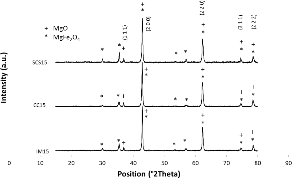
XRD patterns of the catalysts with 15 wt.% Fe after heating to 900°C according the growth heating regime, followed by abrupt cooling. Indices refer to MgO lattice only.
Further XRD studies on NTCC15, as shown in Fig. 4, revealed that the responsible phase from which iron nanoparticles were produced was MgFe2O4. Compared to XRD patterns of CC15 in Fig. 3, one can see that MgFe2O4 peaks have disappeared and a weak peak, which is the strongest peak of α-Fe, has shown up. Upon exposure to methane at 900°C, MgFe2O4 crystals were reduced to metallic iron nanoparticles on MgO (100) facets [24], becoming suitable sites for nucleation and growth of CNTs.

XRD patterns of the as-grown CNTs on CC15 without purification. Miller indices correspond to MgO only.
The SEM images in Fig. 5 confirm the formation of CNTs on all samples, with some CNTs on the surface of catalyst particles and some bridging between them. Branching of CNT bundles, which is a characteristic of SWNTs and DWNTs, is also seen in these images. Since CNTs have covered catalyst particles, a fair estimation of particle size cannot be made. However, the morphology of MgO particles in all powders is in the form of spherical agglomerates, which is confirmed by TEM. The filaments in the SEM micrographs could be individual or bundled CNTs which are hard to distinguish; for this reason, more detailed studies were conducted by TEM. TEM images of samples with 5 wt.% Fe are shown in Fig. 6. MgO particles and tangled and bundled CNTs are observable in Fig. 6a. The arrows in Figs. 6b and d indicate carbon nanofibres (CNFs). Such morphologies of carbon have been previously reported by Coquay et al. [35] for SCS-produced catalysts, and by Ning et al. [8] for impregnated catalysts. These undesirable by-products of the CCVD process grow on iron nanoparticles larger than 5 nm. They significantly impair the properties of CNTs and are very hard to eliminate [7]. Two catalyst agglomerates larger than 300 nm with CNTs on the surface and in between can be seen in Fig. 6c. By referring to the HRTEM image in Fig. 6e, one can see that the product in the NTIM5 specimen mainly comprises single and double-walled CNTs. Arrows

SEM images of a) NTSCS5, b) NTSCS10, and c) NTSCS15, d) NTIM5, e) NTIM10, f) NTIM15, g) NTCC5, h) NTCC10, and i) NTCC15

TEM images of a, b) NTSCS5; c, d, e) NTIM5; f, g, h) NTCC5
The distribution of the number of walls for the three samples with 5% iron is shown in Fig. 7. DWNTs decrease from 42% in NTSCS5 and 40% in NTIM5 to 34% in NTCC5. The SWNT portion increases accordingly, with a negligible amount of CNTs with three or more walls for all samples. The conditions required for the formation of DWNTs and SWNTs have been investigated independently. These include catalyst particle size [25–27], carbon source flow rate [28], catalytic material composition [29], and temperature [26, 30]. However, there are some contradictions between these studies, as the parameters are not always investigated at the same time.
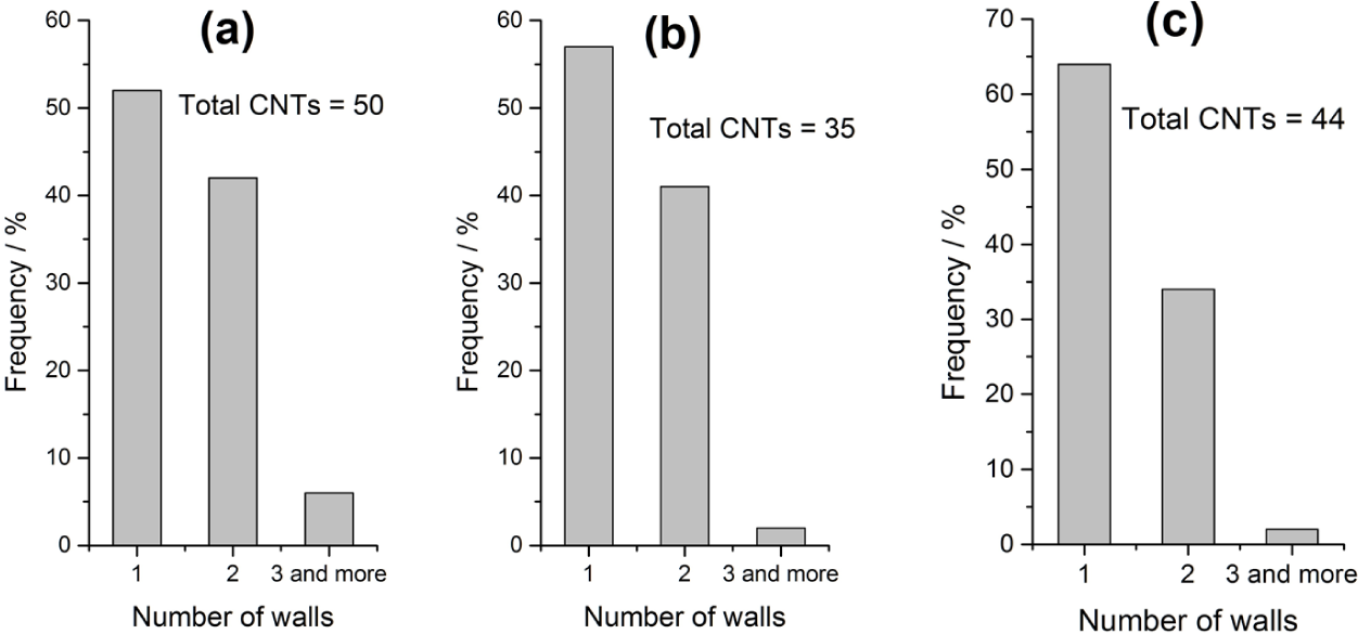
Distribution of the number of walls for a) NTSCS5, b) NTIM5, and C) NTCC5
Raman spectra of as-synthesized CNT samples and the ID/IG ratio variation with iron content are depicted in Fig. 8. This ratio, which is obtained from D and G band intensities in Raman spectra, is a characteristic of nanotube quality. The G band appears at ∼1590, D at ∼1340 and radial breathing mode (RBM) below 400 cm−1. Increase in ID/IG factor is a characteristic of lower quality and presence of more defects in the products. Referring to Fig. 8b, one can see that for each catalyst preparation method, the quality of CNTs decreases with iron content. CNT quality with respect to preparation method can be arranged in the order of NTSCS>NTCC>NTIM. Defects in CNTs are categorized into two groups: structural defects and chemical defects (amorphous carbon). One of the main structural defects that is caused by pore size distribution is bending of tubes due to inhibition of growth space [31]; catalysts with larger pores yield higher-quality CNTs. In addition, Nie et al. have demonstrated that modifying pore structure by ethanol treatment leads to larger particles and pores, and, as a result, CNTs with higher quality [9]. Moreover, Bacsa et al. [32] have reported that the CNT quality is dependent on the specific surface area of the catalyst powders. Likewise, different catalyst fabrication methods must yield powders with different pore structure; consequently, products with various qualities will grow on catalysts. Based on the literature, we anticipate that the pore size in catalysts is highest in SCS and lowest in impregnation, leading to the observed trend in ID/IG for the different preparation methods. Except for NTIM15, this ratio is lower than 0.1 for all specimens, which indicates the high quality of the products [9]. The HRTEM images in Fig. 6 corroborate that the tubes are well crystallized with low structural defects and negligible amorphous carbon.

a) Raman spectra of the as-grown samples and b) ID/IG ratio variation versus iron content for the three catalyst preparation methods
4. Conclusion
In this study, CNTs were synthesized on Fe/MgO catalysts with three different iron contents (5, 10, and 15 wt.%) prepared via combustion synthesis, impregnation, and co-calcination of metal nitrate precursors. The catalyst powders and products were investigated by means of differential thermal analysis, X-ray diffraction, scanning and transmission electron microscopy, and Raman spectroscopy.
XRD patterns confirmed the formation of MgFe2O4 in catalysts upon heating to 900°C, which was found to transform to metallic iron through reduction by methane. TEM studies proved that the CNTs were straight and well crystallized, mostly with one or two walls. The ID/IG ratio obtained from Raman spectra of CNT samples showed that the quality of tubes decreased to some extent with iron content. However, the ID/IG ratio was low for CNTs on all catalysts, showing the high quality of the tubes.
Finally, the co-calcination method was found to be quite easy, quick, and suitable for scale-up purposes, as it requires less equipment and energy and involves fewer steps and raw materials compared to the other common methods. In addition, this study confirmed the good quality and crystallinity of CNTs, which were found to be a mixture of SWNTs and DWNTs with no evidence of carbon nanofibres or thick multi-walled CNTs.
Footnotes
5. Acknowledgements
MBK would like to thank Dr Christophe Laurent, Dr Eduardo Barros, Parisa Sowti Khiabani and Dr SRC Vivekchand for their valuable comments on the paper and Raman spectra. The authors also appreciate the technical support provided by Leeds Electron Microscopy and Spectroscopy (LEMAS) at Leeds University.