
Abstract
In order to compensate the disadvantages of conventional engraving machine and exert the advantages of parallel mechanism, a novel parallel engraving machine is presented and some key technologies are studied in this paper. Mechanism performances are analyzed in terms of the first and the second order influence coefficient matrix firstly. So the sizes of mechanism, which are better for all the performance indices of both kinematics and dynamics, can be confirmed and the restriction due to considering only the first order influence coefficient matrix in the past is broken through. Therefore, the theory basis for designing the mechanism size of novel engraving machine with better performances is provided. In addition, method for tool path planning and control technology for engraving force is also studied in the paper. The proposed algorithm for tool path planning on curved surface can be applied to arbitrary spacial curved surface in theory, control technology for engraving force based on fuzzy neural network(FNN) has well adaptability to the changing environment. Research on teleoperation for parallel engraving machine based on B/S architecture resolves the key problems such as control mode, sharing mechanism for multiuser, real-time control for engraving job and real-time transmission for video information. Simulation results further show the feasibility and validity of the proposed methods.
Keywords
1. Introduction
Conventional computer engraving machine has played an important role in industries such as machinery machining, printing and dyeing and entertainment, but it has the inherent disadvantages such as cutting tool can be fed only along the fixed guideway, lower degree-of-freedom(DOF) of cutting tool, lower flexibility and mobility for machining etc. Parallel mechanism has the merits such as high mechanical stiffness, high load capacity, high precision, good dynamic performance etc(Zhen,H.; Ling-fu,K.& Yue-fa,F.,1997). According to the characteristics of parallel mechanism, it has been a hot research topic to apply parallel mechanism to the domain of future machining. By applying parallel mechanism to engraving domain, its inherent advantages can be fully exerted and the disadvantages of conventional engraving machine can be overcome or compensated. But as the special structure of parallel mechanism, the related theory and technology during its engraving is very different from that of conventional engraving machine, and it is a undeveloped research topic by now. In addition, with the development of computer network technology, the new concept and method such as network machining and manufacturing has become hot research topic(G.Q.,Huang&K.L,,Mak.,2001; Taylor,K. & Dalton, B.,2000; Ying-xue,Y.& Yong,L.,1999). A novel parallel engraving machine with six-axis linkage is proposed in this paper, which uses the 6-PUS parallel mechanism with 6-DOF as the prototype, and some key technologies such as size design, tool path planning, engraving force control and teleoperation are studied on this basis.
2. Confirming of mechanism type and engraving machine's size
2.1 Selection of mechanism and coordinate system
The selection of mechanism type is the first step for designing novel engraving machine, the following reasons make us select the 6-PUS parallel mechanism for designing our engraving machine.
Comparing with traditional mechanism, 6-PUS parallel mechanism uses base platform, three uprights layout and high rigidity framework structure and has the merits such as high modularization, high accuracy and low cost. Its model is shown in Fig.1.

The model of 6-PUS parallel mechanism
As shown in Fig.1, 6-PUS parallel mechanism consists of base platform, dynamic platform and 6 branch chains with same structure, every branch joins with base platform through prismatic pairs(P), slider of prismatic pairs joins with up end of the fixed length link through universal joint(U), down end of the fixed length link joins with dynamic platform through sphere hinge (S), so it is called 6-PUS parallel mechanism.
The coordinate system of 6-PUS parallel engraving mechanism is shown in Fig. 2. In Fig.2, the geometry centers of base platform and dynamic platform plane are supposed as

Coordinate system of 6-PUS parallel engraving mechanism
2.2 Mechanism performance analysis based on influence coefficient matrix
The performance of engraving machine will change with its size. To find out the better size for all the performance indices of both kinematics and dynamics, we obtain a group of mechanisms by changing its parameters. These mechanisms' length of fixed length links (L) range between 45cm and 55cm (step is 1cm), radius of dynamic platform (R) range between 10cm and 20cm (step is 1cm). Other parameters of the mechanism is unchanging, so we get 121 mechanisms totally. Taking these mechanisms as research object, we confirm the sample point for every mechanism in its workspace with algorithm PerformanceAnalysis, then calculate the first and the second order influence coefficient matrix in every point. Furthermore, calculate all the performance indices in every sample point and draw all the global performance atlas of 121 mechanisms ultimately. To describe conveniently, we abbreviate the first and the second order integrated influence coefficient matrix [GqH]6×6 and [HqH]6×6×6 to G and H, and use Gω, Hω and Gυ, Hυ as the angular velocity submatrix and linear velocity submatrix of the first and the second order integrated influence coefficient matrix respectively, namely,
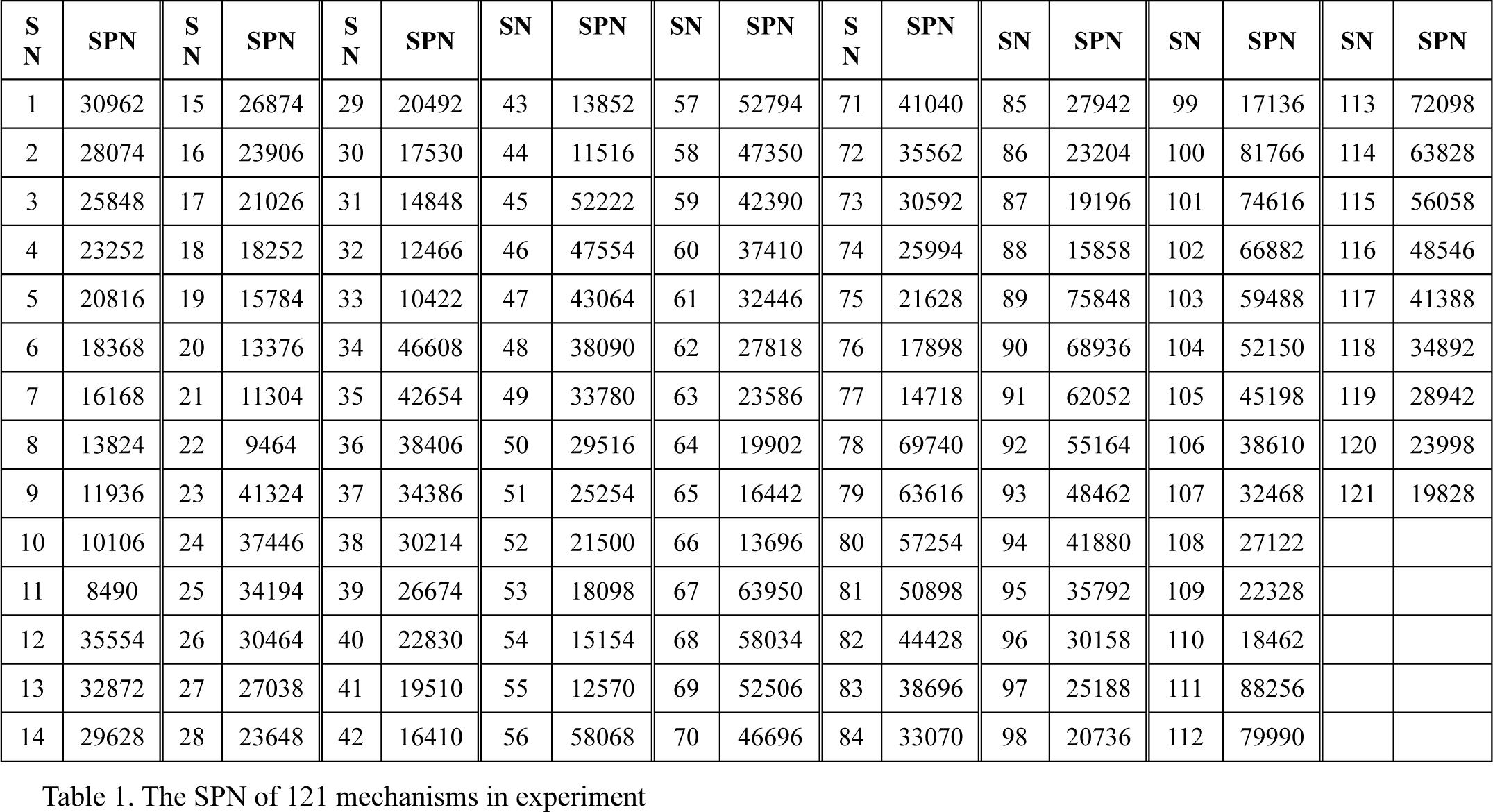
We can change mechanism's parameters and adjust variable's step in the algorithm PerformanceAnalysis to meet actual analysis. The algorithm is programmed with MATLAB and the global performance atlas of 6-PUS mechanism are drawn (see Fig. 3 to Fig. 8), then the mechanism's performance is analyzed using the atlas. Table 1 shows the results of sample point number (abbr. to SPN) for 121 mechanisms respectively, the fixed link length of mechanism with sequence number (abbr. to SN) 1 is 45cm, its radius of dynamic platform is 10cm, the fixed link length of mechanism with SN 121 is 55cm, its radium of dynamic platform is 20cm, the rest may be deduced by analogy. In addition, table 2 gives the performance indices of some mechanism only, where the mean of SN is same as in table 1.
The SPN of 121 mechanisms in experiment
Six performance indices of some mechanisms

Atlas of angular velocity global performance

Atlas of linear velocity global performance

Atlas of angular acceleration global performance

Atlas of linear acceleration global performance
Atlas of global performance of force and moment

Atlas of global performance of inertia force
Description for algorithm PerformanceAnalysis:

2.2.1 Analysis of kinematics performance indices
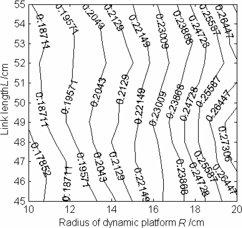
2.2.1.1 Global performance indices of angular velocity and linear velocity
As the influence coefficient G of engraving mechanism is not a constant matrix, it makes the measuring index for parallel mechanism based on G not to be a constant matrix also, so we can't utilize one value to measure the good or bad of the dexterity, isotropy and controlling accuracy(Xi-juan,G.,2002). Here, we define parallel mechanism global performance indices of angular velocity and linear velocity as following respectively

Where W is the reachable workspace of mechanism,
2.2.1.2 Global performance indices of angular acceleration and linear acceleration
Considering the influences on acceleration of both the first and the second order influence coefficient matrix, the condition numbers of angular acceleration and linear acceleration for 6-DOF parallel mechanism are(Xi-juan,G.,2002; Xi-juan,G.& Zhen,H.,2002)


Where, a and b is error coefficient.
So the global performance indices of angular acceleration and linear acceleration for parallel engraving mechanism can be defined as

Where J ∈ {Gω + Hω, Gυ + Hυ}
Supposed the mechanism error is smaller than 2%(that is, a=b=0.02), replacing the underlined part in algorithm PerformanceAnalysis with formula (4), we can draw the performance atlas for angular acceleration and linear acceleration as shown in Fig. 5 and Fig. 6. As same as the evaluating method for velocity performance index, from Fig. 5 we can see that the angle acceleration performance of mechanism is better when nearly L=45cm~47cm and R=16cm~20cm, output error is smaller accordingly. Among the 121 mechanism we studied, its maximum is 0.16399.
By observing Fig. 6 carefully, we know that performance of linear acceleration is better when nearly L=45cm~48cm and R=19.5cm, accordingly, output error should be smaller. From above analysis, we know that mechanism size with good indices for linear velocity and linear acceleration is coincidence in some degree among the 121 mechanisms we studied, but performance index of angular velocity and angular acceleration may not the best in the same size, so it can't get coincidence.
Thus, our analysis will be helpful for designing and choosing mechanism by actual needs. Similarly, analyzing method of kinematics performance indices is the same when other parameters of the mechanism are changed.
2.2.2 Analysis of dynamics performance indices
2.2.2.1 Analysis of power and moment performance index
The condition number of power and moment performance index based on the first order influence coefficient matrix of power GF for 6-DOF parallel mechanism can be defined as(Xi-juan,G.,2002)

Similarly, we define global performance index of power and moment for 6-DOF parallel mechanism as

We suppose that power and moment of parallel mechanism is isotropy when ηJ=1. With formula (5) as condition number, replacing the underlined part in algorithm PerformanceAnalysis with formula (6), we can draw the performance atlas for power and moment as shown in Fig. 7. From Fig. 7 we can see in the size range of our experiment the performance index for power and moment would have little change with the link length when the radius of dynamic platform is less then 14cm. The performance index for mechanism's power and moment will be bigger when L=45cm~46cm and radius of dynamic platform R=10cm, here, performance of power and moment will be better.
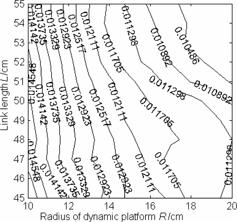
2.2.2.2 Analysis of inertia force performance index
Considering both the first and the second order influence coefficient matrix, the condition number of inertia force for 6-DOF parallel mechanism is defined as(Xi-juan,G.,2002)

Where [Gω]
i
is the ith column of matrix Gω, i=1,2,3. Then global performance index of engraving mechanism's inertia force can be defined as

Obviously, the bigger value of η G+H, the smaller inertia force of mechanism and the higher controlling accuracy. Replacing the underlined part in algorithm PerformanceAnalysis with formula (8), we can draw the performance atlas for inertia force as shown in Fig. 8. According to the rule that the bigger value of η G+H, the smaller inertia force of mechanism and the higher controlling accuracy, by observing Fig. 8 carefully, we can see that the inertia force performance index of mechanism is getting better when the link length is getting longer and radius of dynamic platform is getting bigger. Furthermore, the inertia force performance index of mechanism will be the best when nearly L=45cm~48cm and R=19.5cm, that is to say, the inertia force performance of mechanism is the best, inertia force is the smallest, sensitivity is the best and dexterity is the highest. According to discusses above, we draw a conclusion that mechanism size with good performance index for power and moment and inertia force is coincidence not in all the time. This result indicates that the traditional designing and choosing mechanism method based on only the first order influence coefficient exists some restriction, we have to choose mechanism size on the basis of our analysis and actual demands.
2.3 The results of size design and summary
Summarizing previous analysis, we know that 6-PUS robot mechanism's all performance indices are better except force and moment when L=45cm~47cm and R=19cm, the actual size of mechanism with this type owned by laboratory is at the above-mentioned scope. We also find that its performances are same with the results of theory analysis by running the mechanism in deed, so prove the correctness of our theory. To validate our theory analysis further, we also do lots of simulations for this mechanism with other sizes. The results are same with those of theory analysis, so we can draw the conclusion that, in a generally way, there is not a mechanism whose all indices are better at the same time for both the kinematics and dynamics. In fact, we can only select the mechanism with relative better performance for all the indices to meet our need.
On the basis for considering all the performance indices, the final sizes of novel parallel engraving machine that we designed are following:
The length of fixed link L is 46cm, the radius of dynamic platform R is 19cm, the radius of base platform is 38cm, {φP1,φP2,φP3,φP4,φP5,φP6}={45°,135°,165°,255°,285°,15°}, {φB1,φB2,φB3,φB4,φB5,φB6}={82°,97°,202°,217°,322°,337°}, φ C =30°,φ A =15°. Where φ Pi (i=1, 2, …, 6) is the angle between tieline from dynamic platform's center op to Ci and the axis xp's positive direction of dynamic platform's coordinate system, φ Bi (i=1, 2, …, 6) is the angle between tieline from base platform's center OB to Ai and the axis XB's positive direction of base platform's coordinate system. φ C and φ A is the smaller central angle of hexagon made by Ci and Ai(i=1, 2, …, 6) respectively.
3. Research on path planning of engraving
A series of engraving paths can be obtained after the image of workpiece to be engraved is dealt with image processing technology and tool path generating algorithm(Chih-Ching,L.,1998), these paths consist of a series of straight line segments(exclusive for direction-parallel machining). When engraving on plane, the control of engraving path has the linear mapping relation to the cutting tool path that has been planned. But when engraving on spacial curved surface, the engraving path on plane should be mapped into the path on curved surface, this mapping is more complex than the former. In this section, we will pay attention to cutting tool path's mapping method from plane to spacial curved surface and the planning algorithm of cutting tool's posture.
3.1 Mapping method of cutting tool path
To describe conveniently, supposing the curved surface S to be engraved is

Where D is one region on the uv plane.
Curve C on curved surface S can be expressed as

Then arbitrary point Ci on curve C is

In addition, supposing the image plane of workpiece to be engraved is superposition with coordinate system xOy that describes the curved surface S, then the plane equation describing workpiece image is

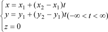
For one cutting tool path on plane with length of d, start and end point is Ps(x1,y1,0) and Pe(x2,y2,0) respectively, which should be mapped into a curve segment when engraving on spacial curved surface. Furthermore, the vertical projection's length of chord length corresponding to curved segment should equal with the straight line segment's length d. The line equation of plane cutting tool path's straight line segment can be expressed as
The equation of plane P that passes plane cutting tool path's straight line segment and is vertical with image plane is

Then the intersecting line of plane P and curved surface S to be engraved is the curve C, on which is cutting tool path on curved surface crresponding to that on plane. By this, the start and end point's coordinates of cutting tool path on curved surface, which corresponding to that on plane, are Ps' (x1,y1,z1) and Pe' (x2,y2,z2) respectively, as x1,y1,x2,y2 are known, z1and z2 can be deduced with equation (10). It is easy to validate that the cutting tool path's mapping method metioned above can suit for arbitrary quadrant of the coordinate system and engraving path in arbitrary direction.
3.2 Interpolation computing of spacial curve
Real-time interpolation computing is necessary to engrave spacial curve segment, whose coordinates of start and end point are Ps' (x1,y1,z1) and Pe' (x2,y2,z2) respectively, with parallel engraving machine. Firstly, the interpolation number N should be calculated by interpolation precision, then the coordinates of ith interpolation point can be expressed as (xi, yi, zi), where

3.3 Posture planning of cutting tool
In view of the special structure of parallel mechanism and ensuring effect for engraving, the posture of cutting tool should be considered during engraving(Yuan-Shin,L.,1997), namely, the posture of cutting tool for every interpolation point should also be calculated besides its position during the control process. For parallel engraving machine with 6-DOF, the rotation around axis ZB is not used in generally, the rotation angle α and β around axis XB and YB will be solved in following.
Supposing the base coordinate system of parallel engraving mechanism in initial state is same with that of curved surface(curve), that is, the axial line of cutting tool of cutting tool is vertical with dynamic platform plane of engraving machine and fixed on it, then the rotation angles of dynamic platform plane around XB and YB both are zero, namely, the angle between axial line of cutting tool and XB and YB both are π/2, as shown in Fig.9(a).

The sketch map of cutting tool's posture for initial state and during engraving
Without losing generality, now taking arbitrary interpolation point Pi (xi,yi,zi) on curve as sample, as shown in Fig. 9(b), then the tangent plane (parallel with the dynamic platform plane of engraving machine) equation of curved surface through point Pi can be expressed as

Translating the general form as

Where

In addition, the line equation of axis XB and Y is as following respectively

According to the relation between spacial plane and line, the angle θx and θy, representing the angle between dyanmic platform plane of engraving machine and axis XB and YB respectively, satisfy


YB respectively. Then we can get
In formula (18) and (19), l1, m1, n1, and l2, m2, n2, represent the parameters of symmetrical line eqution of axis XB and


Here, θx and θy represent the angle β and α, β and α is the rotation angle of dynamic platform plane rotating around axis YB and XB respectively. Positive value denotes counterclockwise rotation, negative value denotes clockwise rotation. Thus, the posture parameter (α,β,0) of arbitrary interpolation point can be obtained, coupled with position parameter above, the position and posture of arbitray interpolation point on curve can be expressed as Pi(xi,yi,zi,α,β,0). So it can be ensured that the axial line of cutting tool at arbitrary interpolation point will be vertical with the tangent plane of engraving point all the time.
3.4 Summary of tool path planning
On the basis of preceeding work, table 3 gives the corresponding relationship between interpolation points of straight line cutting tool path on plane and that of curved surface in space. Based on the theory mentioned above, we simulate the cutting tool path on plane and spacial curved surface when engraving Chinese characters “mu”, as shown in Fig. 10. This section mainly resolves some questions about parallel engraving machine engraves on arbitrary spacial curved surface which is expressed with parameter equation, then realizes the mapping of cutting tool path from plane to spacial curve surface in the workspace of engraving machine. In addition, questions about interference and error analysis are not discussed in this section, the reason is that these questions will be involved only considering the radius of cutting tool, these works will be done in the future.
The corresponding relationship between cutting tool path on plane and curved surface

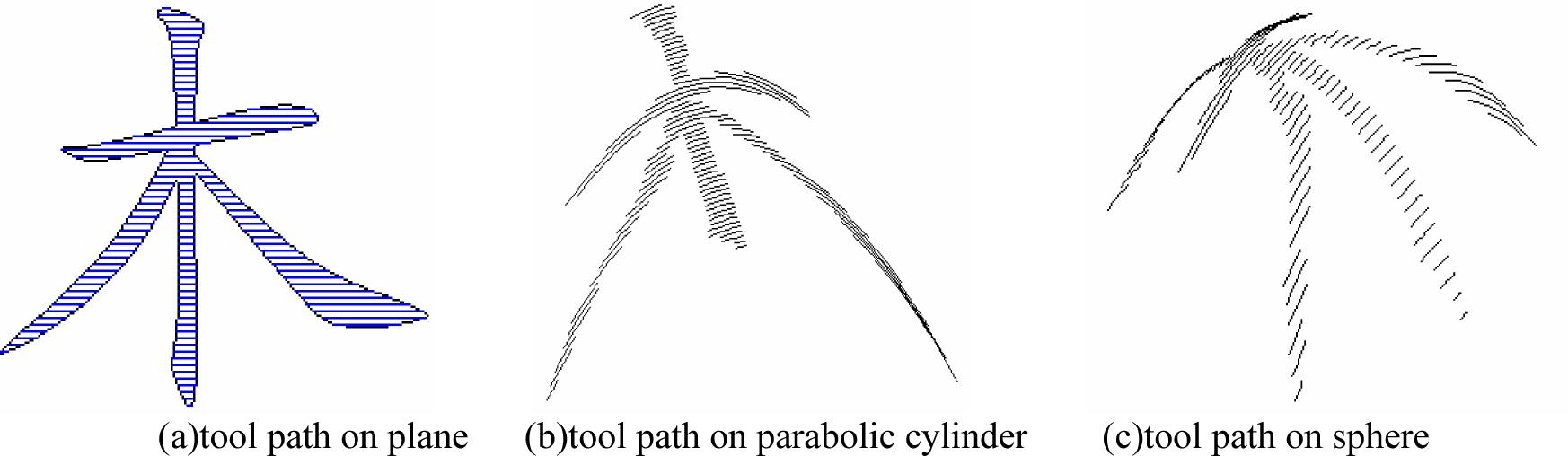
The sketch map of cutting tool path
4. Research on force control technology of engraving machine
Control technology for engraving machine can be classified two types: free motion control and constrained motion control. The control when the cutting tool of engraving machine does not contact with the workpiece is called free motion control. It is called constrained motion control when there is interaction between the cutting tool and the workpiece. Position control can meet demands when cutting tool of engraving machine moves in free space. Not only position but also contact force between cutting tool and environment should be controlled during engraving job. The aim of force control is to realize precise operation, but the first location in large scope is achieved by position control. As position control is relative simple and mature, this section will pay attention to the research on the technology of force control.
At present, force control technology often used can be classified two types of basic and advanced. Basic force control technology also has two schemes: impedance control(Hogan, N., 1985) and hybrid force/position control(M. H.,Raibert. & J. J.,Craig.,1981). Where, impedance is one force control technology developed in early stage, which does not control the force between machine and environment directly but control the dynamic relationship between force and position(or velocity) to implement force control. It is called impedance control because this dynamic relationship is similar to the concept of impedance in circuit. Hybrid force/position control is a scheme that implement force control and position control in “force subspace” and “position subspace” respectively, although its theory is definite, it is difficult to be realized. Basic control method of engraving force is simple and feasiable, it also can achive better control effect when the enviroment parameters are invariable. The precision of basic force control technology depends on the mathematical model of the engrving machine totally as this method's patameters are invariable. We have deduced the accurate dynamics model of engraving machinism in (Ling-fu,K; Shi-hui,Z.; Wen-hui,X.; Cheng-yuan, L.& Zhen,H.,2004) as follow

Where

Please refer (Ling-fu,K; Shi-hui,Z.; Wen-hui,X.; Cheng-yuan, L.& Zhen,H.,2004) for the meanings of all variables in formula (20). According to formula (20), the driving forces for appointed task can be solved when the kinematics parameters and engraving force and moment are known. But as the uncertainty of environment during actual engraving process, conventional method can't be adjusted effectively when parameters are changed, so good control effect can't be obtained, then it is not suitable for the control of engraving machine.
Along with the development of control technology, many researchers introduce advanced control technology to robot force control methods, which causes the appearance of advanced force control technology such as adaptive fuzzy control and neural network(NN) control etc. Fuzzy logic is similar to the thinking approach of human and more suitable for dealing with the uncertain and non-linear issues. Neural network is suitable for parallel computing and has the function of adaptive learning etc. Combining the merits of fuzzy control and neural network technology, fuzzy neural network(FNN) control makes the fuzzy control parameters and rules to be adjusted, modified and perfected automatically during control process, then the control performances of system can be improved constantly and the best control effect can be achieved finally. The control method of engraving force based on FNN technology proposed by us will be discussed in the following.
4.1 The structure and learning algorithm of FNN
We adopt five-layer NN to implement the fuzzy reasoning rules. The five layers are input layer, fuzzified layer, fuzzy association layer, fuzzy postassociation layer and ouput layer.
In the five layers, the nodes of input layer is connected directly to the components of input vector and transports the input values to the next layer. Fuzzified layer completes the calculation of membership function and realizes the fuzzification of input variables, so every node of this layer corresponds to one linguistic variable. Every node of fuzzy association layer represents one fuzzy rule, which is used to match the antecedent of fuzzy rule and calculate the applicable degree of every rule. To given input, the value of linguistic variable only near the input point has bigger membership degree. Fuzzy postassociation layer completes normalized calculation, which prepares for the reasoning process of next layer. Output layer accomplishes defuzzification and outputs concrete value of the FNN. Generally speaking, NN should to be trained before practical application. For engraving machine, its engraving environment is not fixed commonly, the learning result of network for a certain environment is not suitable for other environment usually, so it needs retraining to adapt the new system. Therefore, online learning and adaptive ability is very important to the control of engraving force. Only the output layer has weight in our FNN, and only the local connect weights, which are connected with the activated neurons, are adjusted. The supervised Hebb learning rule(it is a learning algorithm without tutor) is adopted in this paper, which uses the deviation between desired force and actual force as supervised signal, and adjust the position by self-organizing and self-learning to environment information through associated searching, then realizes the tracking of desired engraving force finally.
4.2 The design of force controller
Control framework of engraving force for parallel engraving machine based on FNN is shown in Fig. 11, where the concrete structure of FNN is 2-14-49-49-1.

Control framework of engraving force for parallel engraving machine based on FNN
In Fig. 11, FNN controller uses force error Fe and error changing rate Ḟe as input value, position adjustment ΔX as output value, where Fe ∈ [–1000N,1000N], Ḟe ∈ [–10000N/s,10000N/s], ΔX ∈ [–0.01m,0.01m]. Fd is desired force trajectory, F is the actual engraving force. Ke is stiffness matrix of engraving enviroment, which is commonly a positive diagonal matrix, that is to say, the eviroment is decoupled in all directions. Xd is desired position trajectory. X is the actual position of engraving machine's cutting tool. Xe is the position when the engraving enviroment is not deformed. Fuzzy subsets about input and output linguistic variable of fuzzy controller both are negtive large(NL), negtive middle(NM), negtive small(NS), zero(ZE), positive small(PS), positive middle(PM) and postive large(PL), the following bell function is used as membership function
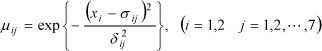
Where σ ij and δ ij is the center and width of membership function respectively. Fuzzy control rule is shown in Table 4.
Fuzzy control rule


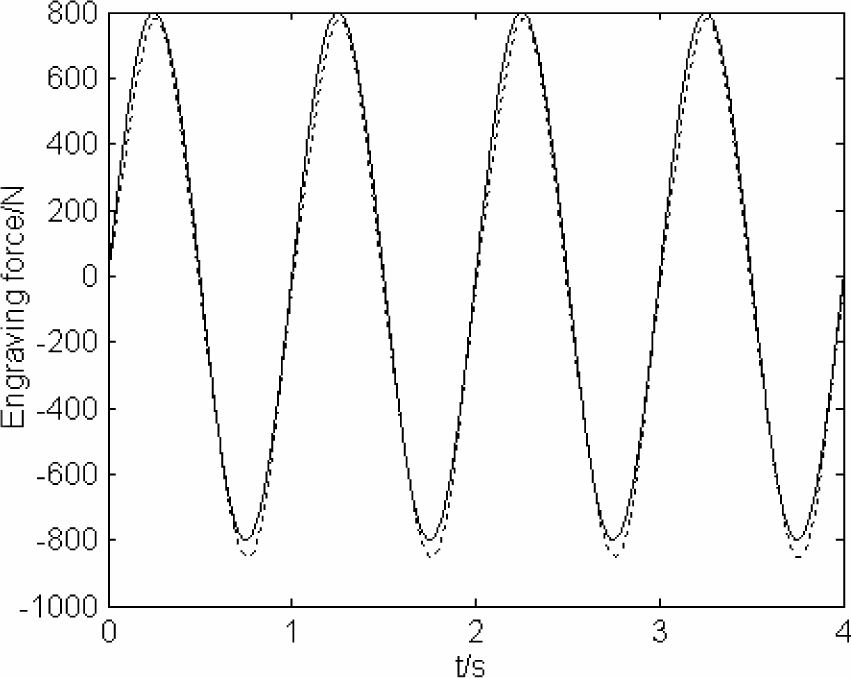
Fig. 12 to Fig. 19 are the simulation results in one direction of degree-of-freedom (which can represent arbitrary direction) based on the control method mentioned above. Where dashed line shows desired engraving force, solid line shows actual engraving force.

Response of step force with 800N

Response of time-changing force with 800sin(2πt+π/5)

Response of step force under environmental stiffness changing (when t=1, Ke changing from 10000N/m to 1000N/m)

Response of sine force under environmental stiffness changing (when t=1, Ke changing from 10000N/m to 1000N/m, and t=3, Ke changing from 1000N/m to 10000N/m).

Response of step force under environmental position changing
Response of sine force under environmental position changing

Response of squarewave force without interfere

Response of squarewave force with noise(0,10)
From above results, we draw the conclusion that the control technology of engraving force based on FNN can make adjustment rapidly according to the changing of environment parameters, the whole system has merits such as rapid response to new environment, small influence by changing parameters, strong adaptability and robustness.
5. Research on teleoperation technology for parallel engraving machine based on B/S mode
5.1 Implementation of teleoperation system
The structure of teleoperation system for parallel engraving machine is shown in Fig. 20, which adapts supervised control model(G.Q.,Huang& K.L,,Mak.,2001). This kind of control model makes operator out of the closed loop for control structure, so the influence on the whole system by transmission delay is decreased. Three parts functions, i.e. motion control, engraving control and video feedback, are provided to the use by web server. Motion control mainly implements the motion of engraving machine such as straight line, circular arc, ellipse and pentagon etc. Engraving control implements related task about actual engraving, including input of information to be engraved, contour extraction, tool path generation, machining simulation and actual engraving, which is the control core of parallel engraving machine and decides the engraving effect. The running state can be monitored real-time by starting the function of video feedback during process of both motion control and engraving control. All functions mentioned above can be shared by multiuser except the control of engraving machine. The mutual exclusion principle between progresses is adopted in our system to prevent sharing engraving machine by multiuser at the same time. The detailed method is: A common variable is used by Cookie technology, every web user will test the state of this variable before actual engraving, “0” represents that the engraving machine can be controlled, “1” represents does not and now the related prompting message such as “system is busy” will be send to user immediately. Once the engraving machine is controlled by one user, the common variable will be assigned to “1” and other users will not use the machine, so the reliability of system can be guaranteed.

The structure of teleoperation system
Engraving task may be canceled by the user for all kinds of reasons during engraving process, which asks the control algorithm for engraving machine have the ability to respond new instruction during control. This question can be resolved by setting a common variable like above, what the control program should do is to test the value of this variable every time before sending control instruction to engraving machine.
In addition, to ensure that only the user who submits the job has qualification to terminate engraving task, the system will return a unique ID to the browser end after engraving task is submitted successfully. The system will ask the user to submit a ID when user want to terminate engraving task and will compare the ID provided by user with the ID of task being executed.
The engraving job will be terminated if the two IDs are coincident, otherwise the system will warn that the user has not the privilege to terminate the task.
The Java Media Framework(JMF) is adopted for real-time transmission of video information. JMF is the application program interface for streaming media developed by SUN, through which the multimedia function is introduced to Java. As Remote Transport Protocol(RTP) has been implemented in JMF, the real-time acquisition and transmission of video information can be realized with JMF easily.
5.2 Experiments for teleoperation
To verify the feasibility of our system, the engraving of straight line, circle, ellipse and pentagon is implemented successfully firstly, on this basis, the engraving of Chinese characters also successes by visiting the engraving server through local area network. In addition, remote engraving and real-time transmission for video information is obtained success further by visiting server through Internet.
Fig. 21 shows the system interface for engraving Chinese characters “zi”. Fig. 22 shows the parameters to be submitted for straight line motion of engraving machine, here the “engraving control” part on the right side of Fig. 21 will change into the content of Fig. 22, similar as “circular arc motion” and other functions.

The interface of teleoperation system for engraving

The submitted parameters for straight line motion
6. Conclusions
A novel parallel engraving machine is proposed and its some key technologies are studied in this paper. Based on the confirming of mechanism type, a group of mechanisms are obtained by changing the sizes of engraving machine. Performance indices are analyzed by considering both the first and the second order influence coefficient matrix of different sample point in every mechanism's workspace, then mechanism's sizes better for both kinematics and dynamics are achieved, so the theory basis for designing the size of novel engraving machine is established. In addition, method for tool path planning and control technology for engraving force is also studied in the paper. The proposed algorithm for tool path planning on curved surface solves path's mapping method from plane to spacial curved surface, which can be applied to arbitrary curved surface in theory. Control technology for engraving force based on FNN also has strong adaptability to the unknown environment. The implementation of teleoperation for parallel engraving machine based on B/S mode can meet the demands of distance engraving for ordinary web user, which also can be expanded to other machining domain besides engraving, so long distance and network machining can be realized. Simulation experiments are done based on the proposed model of engraving machine and related methods, simulation results show the feasibility and validity of the proposed methods. Beneficial exploration has been done for further design and development of future novel engraving machine in the paper.