
Abstract
This article puts forward inductive magnetic suspension spherical active joints and has researched on its mechanism. The expression of motor’s electromagnetic torque is derived from the point of power balance of three-dimensional electromagnetic model, and on the basis of the air gap magnetic flux density distribution, we establish the joint’s mathematical model of electromagnetic levitation force. The relationship between the two of displacement, angle, and current and the transfer function expression of motor system are derived by the state equation and the inverse system theory We established the inverse system of joint’s original system using fuzzy neural network theory and simplified coupling relationship of the motor’s complex multivariable to establish ANFIS model of joint’s inverse system. An internal model controller with high robustness and stability was designed, and an internal model control joint pseudo linear system was built. According to the simulation analysis and experimental verification of the joint control system, the conclusion indicates that the rotor has quick dynamic response and high robustness.
Keywords
Introduction
Generally, robot and manipulator are driven by single-degree-of-freedom driving components and complex mechanical transmission mechanism to realize space three-dimensional (3D) motions. This leads to a series of problems such as an increase in the degree of complexity of the system, a large volume, serious abrasion of the joint’s friction surface, low efficiency, lack of precision, slow response, and poor dynamics.1,2 As a research starting point, this article raises and designs the inductive magnetic suspension spherical active joint system to replace the traditional robot and manipulator joint, which can not only simplify the complexity of the mechanism but also realize suspension without friction and abrasion between the motor’s rotor and stator, improve the rotor’s positioning accuracy and speed response, and reduce the volume to achieve the purpose of rapid response.
Inductive magnetic suspension spherical active joint is a strong coupling and nonlinear system; the rapid development of science and technology increases the requirements of automatic control in the production of uncertainty and complex system. Control of quality improvement in industrial production can bring better economic benefit, which is realized by advanced controller. When fixed parameter proportional–integral–derivative (PID) control is affected by large disturbance, it is easy for integral saturation to appear and it is unable to reach the control demand.3,4 At present, many related literature has put forward some design methods of adaptive controller, such as model reference adaptive control and smoothing model control. Although these control methods can improve the performance of the motor driving system, these rely on the known mathematical model and fixed parameters and structure of the model. In recent years, fuzzy logic has developed rapidly in the field of intelligent control and has gained wide application, because fuzzy control is largely dependent on the experience offered by experts, with low adaptability.
This article uses robust control of fuzzy neural network inverse system and takes into account the advantage of neural network. It is organically combined with fuzzy logic to produce adaptive fuzzy neural network and connected in series to the original system. Linearize the inductive magnetic suspension spherical active joint original system and then take control of the system by model control of high robustness and stability. With the study on mechanism of the inductive magnetic suspension spherical active joint system, 5 we established electromagnetic suspension force and electromagnetic torque models of joints6,7 and 3D dynamic nonlinear coupling model of joint’s ideal spherical rotor. At the same time, it constructs the fuzzy neural network inverse system of the original joint system and designs the internal model controller of the pseudo linear system to control and study the characteristics of joint suspension and rotation.
Operation mechanism of inductive magnetic suspension spherical active joints
The overall 3D structure of inductive magnetic suspension spherical active joint is shown in Figure 1. A magnetic suspension spherical active joint consists of the cube, six stators of pairwise symmetric structure, rotor, five electromagnets, and a number of auxiliary parts. The electromagnet is connected with the nylon cushion ring, whose spherical surface and spherical surface of the rotor are adjusted by the connection of electromagnet thread, and the action of nylon cushion ring depends on the electromagnet’s electricity and the loss of power. When the spherical joint is not activated, the electromagnet is in the current state, and the electromagnet push rod extends to drive the nylon cushion ring to clamp spherical rotor, which makes the rotor to suspend in the spherical center. When the spherical joint electrically starts, the electromagnet push rod draws back, the rotor is released, and the rotor is suspended at work.

Inductive spherical active joint 3D model.
Figure 2 shows the structures of stator and rotor. The joint stator has 4 poles and 12 slots, as shown in Figure 2(a). The material of stator is steel DW465-50. The joint of inductive spherical active joint is shown in Figure 2(c). The structure contains a lot of big holes, and through these holes electrical strip conductors are put into, similar to the squirrel cage structure but slightly different. Because it is used by the radial guide bar, one end is connected to the inner wall of the inner diameter of the ball rotor. The inner cavity diameter forms a connection when coated with a layer of aluminum material. The outer surface of the rotor slot is filled with aluminum material and is connected with the other end of the radiation bar. The way can form the coil loop of the rotor itself, and each intersection point of longitude and latitude grooves has a guide bar.

Stator–rotor structures: (a) stator, (b) rotor, and (c) rotor armature structure.
When a group stator’s coil of a joint direction powers up with the three-phase alternating current power, it is similar to the common single-degree-of-freedom motor. Joint stator winding provides a rotating magnetic field for a spherical rotor. The radial squirrel cage bars of spherical rotor cut magnetic lines in the rotary magnetic field to induce electromotive force; hence, there will be induced current in the bar. In the interaction between the stator rotating magnetic field and rotor-induced magnetic field, it is possible to obtain not only the electromagnetic torque of inductive joint but also the electromagnetic force which can make the rotor suspend in the radial direction in order to maintain the stability of radial suspension.
Mathematical model of inductive magnetic suspension spherical active joints
Suspension force of joints and electromagnetic torque model
Based on the fuzzy neural network inverse system decoupling, we established mathematical models of electromagnetic force and electromagnetic torque of inductive magnetic suspension spherical active joints. We found out the relationship between the output and input and provided reasonable output and input training dates for the fuzzy neural network inverse system’s training.
Electromagnetic model of inductive magnetic suspension spherical motor
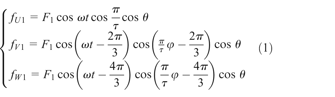
According to the structure of inductive spherical active joint, there are six sine windings in the stator inner spherical surface, and they are Wx 1, Wx 2, Wy 1, Wy 2, Wz 1, and Wz 2. Among them, the axis of Wx 1 and Wx 2 coincides with the x-axis of space coordinate system, the axis of Wy 1 and Wy 2 coincides with the y-axis, and the axis of Wz 1 and Wz 2 coincides with the z-axis. Figure 3 shows the distribution of a certain stator around the spherical surface. Ignoring the harmonic component and slot leakage inductance, end winding leakage inductance, and magnetic saturation effect, the fundamental magnetic potential equations of the three-phase stator windings are obtained as follows

Spherical distribution of a three-phase winding of a certain stator.
where τ is the distance, F
1 is the amplitude of the fundamental magnetic potential,
In the stator static coordinate system x, y, and z, the voltage balance equation of magnetic suspension spherical joint stator and rotor winding is
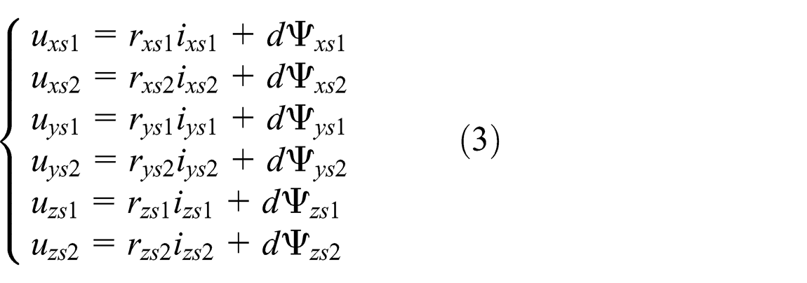
where rxs 1, rxs 2, rys 1, rys 2, rzs 1, and rzs 2 are resistances of the six stator windings, respectively; Ψ xs1, Ψ xs2, Ψ ys1, Ψ ys2, Ψ zs1, and Ψ zs2 are fluxes of each winding, respectively; d is differential operator d/dt; and ixs 1, ixs 2, iys 1, iys 2, izs 1, and izs 2 are currents of the six stator windings, respectively.
In the rotor coordinate system x, y, and z, rotor voltage equation is as follows
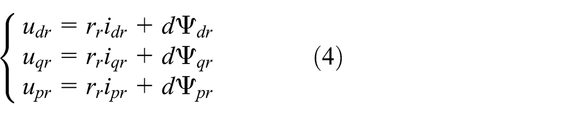
where the rotor winding bars symmetrically distribute and have equal resistance, which is represented as rr ; Ψ pr , Ψ qr , and Ψ dr are the rotor fluxes; and idr, iqr , and ipr are the rotor winding currents.
After coordinate transformation of equation (2), the voltage balance equations of rotor in the stationary coordinate system are as follows
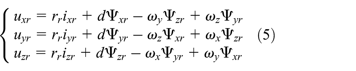
where ωx, ωy , and ωz are the components in the x-, y- and z-axes of angular speed of the rotor and Ψ xr , Ψ yr2, and Ψ zr are fluxes of the rotor’s equivalent winding.
In the coordinate system x, y, and z, the flux linkage equations of stator and rotor windings are as follows

where Lx 1, Lx 2, Ly 1, Ly 2, Lz 1, and Lz 2 are mutual inductance of six stator windings and rotor windings; Lx is the composition of Lx 1 and Lx 2; Ly is the composition of Ly 1 and Ly 2; Lz is the composition of Lz 1 and Lz 2; Lxs 1, Lxs 2, Lys 1, Lys 2, Lsz 1, and Lzs 2 are self-inductance of the stator winding; and Lxr, Lyr , and Lzr are self-inductance of the rotor winding.
The inductance is constant, assuming that Lx = Ly = Lz, Lxr = Lyr = Lzr, Lxs = Lys = Lzs , and substituting equation (4) into equations (1) and (3), the voltage balance equation whose variables are the stator current and rotor angular velocity is obtained as follows

where
Joint electromagnetic torque equation
The voltage matrix multiplies
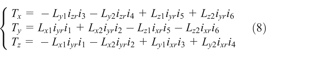
where i 1, i 2, i 3, i 4, i 5, and i 6 are current of six stators of magnetic suspension spherical active joint, respectively.
As is shown in equation (6), the electromagnetic torque of inductive magnetic suspension spherical active joint contains not only three-axis torque component but also complex coupling relationship between the three torque components and rotor current.
Joint electromagnetic suspension force equation
According to the definition of magnetic energy, the magnetic energy of inductive magnetic suspension spherical active joint is
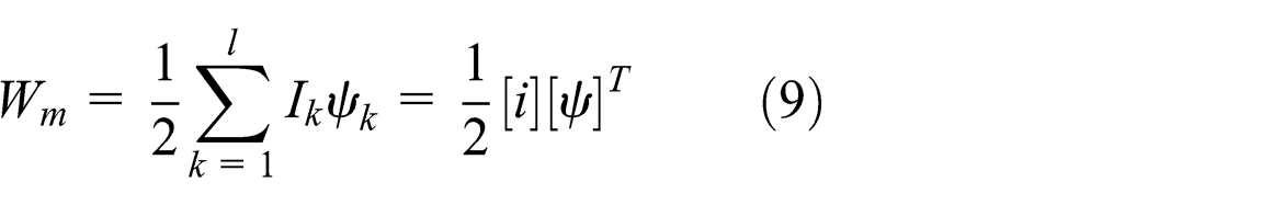
where
According to the principle of electromechanical energy conversion, electromagnetic suspension force model of inductive spherical active joint is

where ρ is the radial displacement of the rotor to stator.
Calculating the magnetic energy of six stators of inductive magnetic suspension spherical joint and overlying them, the total magnetic energy equation of inductive magnetic suspension spherical active joint is determined as follows

Thus, in the stationary coordinate system, the magnetic suspension forces in the x-, y-, and z-axis directions are as follows

Equation (10) shows that the electromagnetic suspension force of inductive magnetic suspension spherical active joint not only consists of three-axis force component but also shows a complex coupling relationship between the components of three magnetic suspension forces and rotor current.
Dynamic equation and state equation of joint
When the spherical rotor of inductive magnetic suspension spherical active joint is in rotation and suspension, it is a rigid body with 6 degrees of freedom. Zeng et al. 8 have shown the dynamic equation and the state equation of inductive magnetic suspension spherical active joint.8,9 Assume that the moment of inertia of the three axes on rotor coordinate system is equal to no additional load. According to the Lagrange principle of dynamics, the dynamics equations are derived for the rotor rotation and suspension

The state equation of magnetic suspension spherical active joint converted by equation (11) is as follows
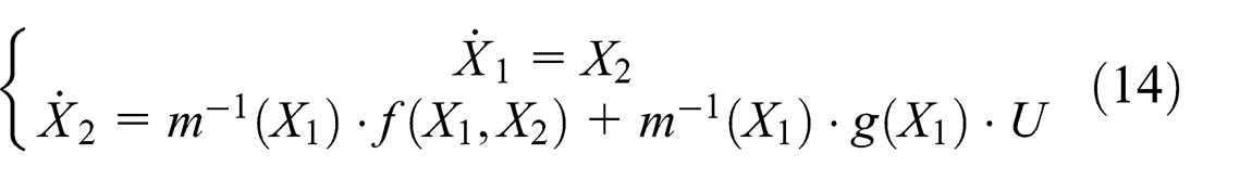
where
The output equation is as follows

According to the analysis of inverse system decoupling, 10 magnetic suspension spherical active joint has inverse system. According to equations (12) and (13), joint linearization decoupling can be realized only by fuzzy neural network constructing of inductive spherical active joint. It can be learned by output equation Y = X 1 that

The inverse system can be expressed as follows

Based on equations (16) and (17), the magnetic suspension active joint could be carried on the internal model control.
Inverse system of fuzzy neural network
MATLAB produced an inference system that combines fuzzy logic and neural network. It makes up for the shortcomings of neural networks and adds the advantages of fuzzy logic, by which the two complement each other and have more superior performance. This system is known as adaptive neural fuzzy inference system (ANFIS). From the datasets of input and output given, construct a fuzzy inference system (FIS) with ANFIS editor. Parameters associated with the membership function may be changed through the learning process. ANFIS or the back-propagation algorithm used by it and the least square method combined together predict and optimize the parameters of membership functions. The structure of ANFIS based on the first-order Sugeno model is composed of five-layer network, as shown in Figure 4.

Structure of ANFIS based on the first-order Takagi–Sugeno model.
In Figure 4, x 1 and x 2 are the inputs of network, y is the output of the network, the function of each node of every layer is similar, and the rule base is composed of the following rules

The first layer is the network model input layer, the input node is linear, including two neurons, and the input signal x = [x 1, x 2] T is transmitted to the next layer in the network.
The second layer is the network’s hidden layer. The memberships function [x 1, x 2] T of fuzzy sets calculates the input component belonging to linguistic variables. Here, the membership function is Gauss function, that is

where cij and σij represent the center and width of the membership function, respectively; i = 1, 2, ..., n; j = 1, 2, ..., mi; n is the input dimension 2; the input dimension of vector [x 1, x 2] T is 2; and mi is fuzzy partition of input number 3, that is, A 1 –A 3 or B 1 –B 3 in Figure 4.
Each node of the third layer represents a fuzzy rule, used to match the antecedent of fuzzy rules and calculate the application of each rule. That is

where j = 1, 2, ..., m;
The total number of nodes in the layer is N 3 = m. For a given input variable, only when the linguistic variables are near the input point, the membership degree value is maximum. Far from the input point, the membership degree value of the linguistic variables is small or 0. When the membership function is very small (less than 0.05), it is equal to 0.
The number of nodes in the fourth layer is the same as the number of nodes in the third layer, that is, N 4 = N 3 = m; it is the realization of the normalization, that is

The fifth layer is consequent network, which is used to calculate each rule, that is
where j = 1, 2, ..., m.
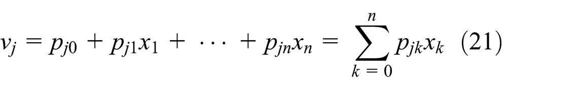
The second component of each rule becomes connection weight of the last layer in the simplified structure, and the output of the system is

As we can see, ν is the weighting sum of rules, and the weighting function is the relevance grade of the normalized fuzzy rules. The output of the front network is used as the back network connection weights.
Assume that the fuzzy segmentation number of each input variable is determined in advance, then the parameters that need to be known are the connection weights of network back component pij (j = 1, 2, ..., m; i = 1, 2, ..., n), the center value cij (j = 1, 2, ..., m; i = 1, 2, ..., n), and width σij (j = 1, 2, ..., m; i = 1, 2, ..., n) of membership function of each node in the second layer of the front network.
ANFIS not only has the advantage of not knowing the exact model of the object and strong anti-interference in fuzzy system but also has the advantage of neural network self-studying and high control accuracy Using it to construct a complex nonlinear coupling system will help construct an inverse system of high performance and accuracy. 11
The inductive motor’s inverse system constructed by fuzzy neural network is connected in front of the original system and forms n pseudo linear system; the pseudo linear system of the first order is shown in Figure 5.
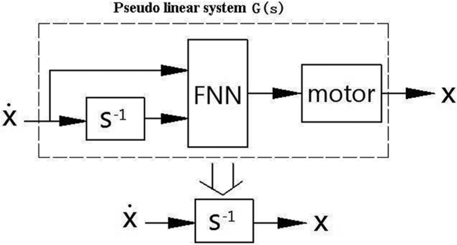
Pseudo linear system.
ANFIS toolbox of MATLAB is used to train ANFIS editor. ANFIS used by this joint system is a first-order Sugeno model. Because 6 degrees of freedom of magnetic suspension spherical active joint are controlled independently, this article only analyzes ANFIS inverse system structure of the 1-degree-of-freedom joint. Assuming research directional displacements, the inputs are displacement error and displacement error rate. In order to accurately simulate, the number of fuzzy set is 7. The membership function is Gauss function, allowed error is 10−3, training time is 1500, and the output is a stator current value of direction. The input and output data can be achieved from MATLAB for the control simulation experiment of joint PID.
Design of internal model controller
The internal model control structure diagram is shown in Figure 6. Model and objects are in parallel connection. The controller is inverse system from the point of theory. The filter controller is introduced on the basis of original controller considering the robustness of system.

Basic structure of internal model control.
In Figure 6, yp
is the object output,
Joint inverse system constructed by fuzzy neural network series in front inductive magnetic suspension spherical active joint model. Inverse system seried infront of joint system expressed by equation (18) is two order differential molecular system, that is the six single inputs and single output system, the transfer function of the system is

According to the classical control theory, the above integral pseudo linear system is open-loop and unstable. In order to solve problems of open-loop and less stability, this article uses the method of generalized inverse system to obtain the generalized pseudo linear subsystems 12 as follows

By adjusting the values of a 2, a 0, and a 1, we reasonably configure poles of pseudo linear composite system.
The transfer function is obtained, that is, the micromolecular system of inductive magnetic spherical active joint inverse system model. It will be taken as

The internal model controller is

Expression for the first filter is

Expression for the second filter is

where λ is the time constant determined by performance index, and substituting a filter expression into equation (23), we obtain
Assuming that
When the external disturbance is
When the external disturbance is
Similarly, expressions of the second filter into equation can be obtained:
When the external disturbance is
When the external disturbance is
When the external disturbance is
From above, we can see that the ability to suppress disturbance of internal model control is very strong, using the internal control of pseudo linear integral inverse system. When using the first filter, the system can completely inhibit the disturbance of the step signal. When using the second filter, the system can completely inhibit the disturbance of the step signal and ramp signal.
Aiming at the complexity and unpredictability of disturbance for magnetic suspension active joint, and based on the same order principle of internal model control, we select the strong function second order filter, that is
λ can be selected in the conditions of experiment and simulation to achieve the desired robust performance. The internal model controller can be expressed as
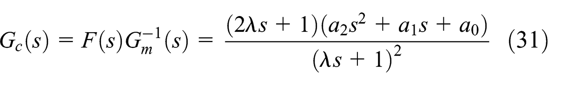
where a 2, a 0, and a 1 are constants and can be selected in the experimental and simulated conditions to achieve the desired robust performance. Therefore, fuzzy neural network internal control structure of inductive magnetic suspension spherical active joint in the single degree of freedom is shown in Figure 7.
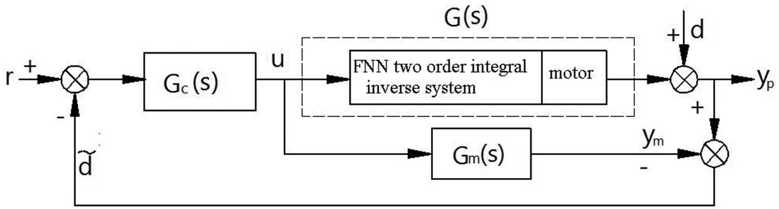
Internal control structure of fuzzy neural network inverse system.
Simulation results and its analysis
The parameters of inductive magnetic suspension active joint are f = 50 Hz, R 5 = 2.3 Ω, Rr = 1.2 Ω, J = 5.8 × 10⁻⁴ kg m2, Lxr = Lyr = Lzr = 0.5 H, Lxs =Lys = Lzs = 0.537 H, Lx = Ly = Lz = 0.55 H, and U = 380 V. Based on the above data, use PID control and simulate the joint to have six data acquisitions. One half is the random speed signal in the amplitude range [0, 50] rad/s when applying the amplitude in the three input speed end of closed-loop control. The other is random displacement signals in the amplitude range [−0.2, 0.2] mm when applying the amplitude in the three input displacement end of closed-loop control. We can obtain six groups of training samples of fuzzy neural network ANFIS inverse system. The time of each simulation is 200 s, and then simulation data are obtained in 2000 groups. Finally, we selected 200 pairs of input and output data in the range. The six groups of data are normalized and used as ANFIS training sample. We randomly selected 50 groups’ input and output data in 2 ms sampling period as the testing sample to test the ANFIS generalization performance and determine whether they have been fitted. Since each pseudo linear subsystem has an internal model and a controller, the structure is complex. So, ellipsis in Figure 8 expresses the other internal model structure that could not be expressed.

Control system structure.
When the inductive spherical active joint is in the no-load state, the initial position of the rotor in the stationary coordinate is 0, 0, respectively. But because the rotor is docked at the z-axis of the stator when the rotor is static, the initial position of direction is −200 µm, the simulation time is set to 1.2 s, and the load torque is T = 0.
In order to see the advantages of the design of the control system, using PID control and fuzzy neural network inverse robust control, two kinds of control methods, the speed response and direction of the displacement response are compared. Comparison can be seen in Figure 9; the use of robust control, fuzzy neural network inverse overshoot volume is small and more responsive, and it can achieve a given speed at 0.3 s.

Response of speed curve: (a) the speed response of PID control and (b) speed response of internal model control.
It draws the method of fuzzy neural network inverse control from the comparison results of displacement response in figure 10, method of fuzzy neural network inverse control, the radial position displacement of the rotor is very small and the maximum overshoot is less than 50 µm in response process. Rotor arrives at the equilibrium position of the z-axis direction at 0.5 s.

Displacement response in the z-axis direction: (a) displacement response of PID control and (b) displacement response of internal model control.
Figure 11 shows that when it = .6 s, speed n suddenly changes to 500 r/min which shows as the curve of methods of fuzzy neural network inverse robust control. As we can see, the fuzzy neural network inverse control system can track the change in the given speed. Stable error is less with fast response. It can achieve stable running speed within 0.3 s. After the stable operation, speed overshoot is less than 10 r/min, the steady-state error is small, and the robustness is more stable.

Speed tracking curve on the mutation condition.
Experimental research
According to the structure studied in the paper of fuzzy neural network inverse system internal control, we established control experimental devices of inductive magnetic spherical active joint, as shown in Figure 12.

Control system of joint machine.
Figure 13 shows that when the rotational speed is 1000 r/min, the speed response of spherical joint, the stable speed can be achieved in 0.3 s and the overshoot is less than 10 r/min. Figure 14 shows variation of the electromagnetic torque with the rotational speed. With the increase in the rotate speed, torque fluctuation gradually becomes smaller. When the rotational speed reached 1000 r/min, the torque is 0, but there is still a small fluctuation.

Speed variation.

Variation of electromagnetic torque with the rotational speed.
Figure 15 shows the rotor displacement response; the initial clearance of rotor downward shift is 0.2 mm. In the suspension control function, spherical rotor will move to the center of the stator to achieve stable suspension. In the stable suspension, the rotor fluctuations are small. Figure 16 shows the variation of acceleration when the spherical rotor is floating. As can be seen that the rotor suspends within 0.4 s, accompanied by a small constant vibration, the vibration becomes 0.

Variation rules of rotor displacement.

Variation of displacement and acceleration.
Figure 17 shows that when the rotor is given around x-axis output angle 45° by control system, they are angle response curves detected of rotor around three axes. Rotor speed of rotation around x-axis stabilized at 0.5 s to achieve a given angle rapidly. And the rotor angle around y-axis and z-axis is less than 5° with small fluctuations in 0.4 s and then gradually tends to 0. Figure 18 shows the angular velocity curve of rotor.

Angle response curves.

Angle speed response curves.
Conclusion
This article designed the mechanical structure of inductive spherical active joints. On the basis of the theory of electromagnetic field and the principle of the motor operating mechanism, it analyzed the motor operating mechanism and working principle.
According to the principle of electromechanical energy conversion, the laws of electromagnetic induction, and Newtonian mechanics theory, this article derived the expressions of electromagnetic torque and electromagnetic suspension force. According to the two equations, the relationship is derived between speed, angle, and current. The transfer function expression of motor system can be derived from the state equation and the inverse system.
Construct the inverse system of inductive spherical active joint system by ANFIS and serie the inverse system with the mathematical model of the original system, which composes a pseduo linear system, controlled by internal control method.
Make characteristic simulations on rotor displacement and speed of inductive magnetic suspension spherical active joint. The simulation results show that dynamic response and robustness of the fuzzy neural network inverse system decoupling and the method of internal control are good. Based on the control structure, we established the experimental devices of the joints. Experimental results show that the rotor has fast dynamic response and strong anti-interference.
Footnotes
Academic Editor: Yong Chen
Declaration of conflicting interests
The author(s) declared no potential conflicts of interest with respect to the research, authorship, and/or publication of this article.
Funding
The author(s) disclosed receipt of the following financial support for the research, authorship, and/or publication of this article: This work was supported by National Natural Science Foundation of China (grant no. 51375427) and Jiangsu Provincial Natural Science Foundation of China (grant no. BK20131232).