
Abstract
This paper presents an adaptive controller equipped with a stiffness estimation method for a novel material-testing machine, in order to alleviate the performance depression caused by the stiffness variance of the tested specimen. The dynamic model of the proposed machine is built using the Kane method, and kinematic model is established with a closed-form solution. The stiffness estimation method is developed based on the recursive least-squares method and the proposed stiffness equivalent matrix. Control performances of the adaptive controller are simulated in detail. The simulation results illustrate that the proposed controller can greatly improve the control performance of the target material-testing machine by online stiffness estimation and adaptive parameter tuning, especially in low-cycle fatigue (LCF) and high-cycle fatigue (HCF) tests.
1. Introduction
In recent years, parallel robots have been extensively investigated due to their innate superiority over traditional serial manipulators. Virtues such as high stiffness, high accuracy, and low inertia are making the parallel robot more and more popular in various industry fields. The original 6-DOF parallel manipulator, which is usually called a Stewart Platform [1], was first established for motion simulators, and parallel robots were then improved for many different purposes [2, 3]. Being different from the classic serial structures, the moving part of the parallel robot is usually light-weight and sustained by more than three kinematic chains, which leads to higher stiffness and better accuracy [4].
When employed as load simulators or material-testing machines, the serial structures are easily subject to link deflections under heavy external loads. Those deflections have a significant effect on robot performances when dealing with tasks involving both position and force controls. On the other hand, with their higher stiffness the parallel robots perform better, especially when employed as a loading mechanism such as a material-testing machine. The stiffness properties of parallel robots have been intensively studied [5–10] and various physical interpretations of stiffness of the parallel robots have been given [7, 8, 11, 12]. For a parallel robot with a symmetrical structure, there always exists a compliant axis and stiffness centre in the z-axis direction. The parallel robot has better operation along the compliant axis because the force and deformation will not affect any other directions [7]. From the stiffness point of view, when used as loading machines parallel robots will exhibit the best performance along the compliant axis. The Stewart platform, whose moving platform is sustained by six short kinematic chains, can achieve higher stiffness easily. Hence, born with a higher stiffness, parallel robots will perform better, especially when employed as material-testing machines [13].
Although various force control approaches have been proposed in the literature and applied for serial machines, force control methods for parallel robots have rarely been addressed because of the complexity of their mechanical structure, which makes it difficult to solve the Forward Kinematic Model (FKM) as well as to obtain the dynamic models of parallel robots. The two basic approaches to force control are hybrid position/force control [14] and impedance control [15, 16]. For hybrid position/force control, the task space is partitioned into independent position-controlled and force-controlled directions and each subspace is controlled independently by two separated controllers. On the other hand, for impedance control a certain relationship between the interaction forces and the end effector configuration needs to be developed without controlling the force explicitly. The force exerted on the environment by the parallel robot depends on its configuration and impedance. The applied force can be controlled well only if the positional trajectory is exactly planned. However, most of the time the environment properties cannot be precisely obtained and the input trajectory always contains errors.
So far, most of the contrived control methods, including impedance control and hybrid position/force control, have been firstly designed for serial robots and then migrated to parallel robots. The hybrid position/force control method has already been used in the control of parallel manipulators [17, 18] as well as multi-axis material-testing machines [19]. In these previous studies, the environment stiffness has rarely been explicitly evaluated and introduced into the control scheme; it is usually assumed that the environment stiffness is invariable or not sharply changed during the running time of the controlled machine. These assumptions suit many industrial applications, but are not suitable for material-testing machines. The stiffness of a metallic specimen is supposed to be invariable at the elastic deformation stage, changing largely after the yield point. The alternation of the stiffness prominently affects the performance of the controller [20].
In this paper, a 6-DOF material-testing machine based on the Stewart Platform is proposed and an adaptive control method is presented, which is able to estimate the stiffness of the specimen online and tune the control parameters in real time.
The remainder of this paper is organized as follows: section 2 presents the architectural description, kinematics and dynamics of the 6-DOF material-testing machine; in section 3, stiffness matrix supports and a stiffness estimation method are introduced; the proposed adaptive control method is developed in section 4; simulations and discussions of results are given in section 5.
2. Model descriptions
The proposed 6-DOF parallel material-testing machine is composed of six identical motor-driven kinematic limbs connecting the fixed base to the moving platform with a spherical joint followed by a prismatic joint and a Hook's joint, as depicted in Figure 1. As shown in Figure 1, for each of the six kinematic limbs a force sensor is installed while the specimen is mounted between the moving platform and the fixed base using two grippers.

Configuration of 6-DOF material-testing machine: (a) solid model; (b) the prototype
Figure 2 explains the definitions of the two coordinate systems: the coordinate system

Schematic for definitions of the coordinate system and vectors: (a) three-dimensional view; (b) bottom view
The geometric parameters of the designed machine are elaborated in Table 1.
Geometric parameters of the proposed machine

2.1 Kinematic model
Kinematics focuses on the relationship between the displacements of the moving platform and the linear motions of the kinematic limbs. Inverse kinematics attempts to calculate the displacements and velocities of the actuators according to a given set of states of the moving platform; forward kinematics does the opposite. In an inverse kinematic analysis, the displacements and velocities of the actuators can be expressed in the following form [21]:


where
Forward kinematics attempts to determine the posture of the moving platform with respect to the body frame

where
2.2 Dynamic model
The dynamic model of the parallel material-testing machine can be derived in many different ways, using for example the Lagrange, Newton-Euler, or Kane methods, or the principle of virtual work [20, 22–24]. In this paper, the dynamics model of the parallel robot is established using the Kane method, assuming that all the components of the parallel robot are rigid. It is also assumed that the proposed machine is mechanically designed to be no singularity in its workspace. The dynamic model can then be expressed as:
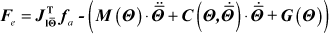
where
In general, the geometric and inertial parameters of the mechanical system can be measured before assembling, and those of the actuation system can be obtained from catalogues. With reference to eq.(4), the applied force
3. Stiffness estimation
3.1 Stiffness equivalent matrix
For a classic uniaxial material-testing machine, the displacement of the actuator is often adjusted by a PI controller to achieve the expected force value. The relationship between the applied force and the actuator displacement is simply represented by the stiffness of the specimen. However, a parallel robot is quite different from a uniaxial loading mechanism because both the forces and displacements of the actuators cannot be linearly translated to the worktable, and the environment stiffness cannot simply be replaced by a consistent stiffness matrix either [5, 25].
As shown in eq.(2), the actuator velocity of the target mechanism can be represented by the generalized velocity of the moving platform

where
In an infinitesimal time interval, the displacements of the moving platform and the actuators of the target machine can be ignored and the Jacobian matrix
Eq.(2) and eq.(5) can also be altered:

where
In practical work, each of the six limbs of the proposed machine is controlled by an independent controller, and the environment stiffness can be decomposed according to the direction of the limb vectors. Let

Combining eqs.(6)–(9), the equivalent stiffness matrix
3.2 Stiffness estimation method
For a material-testing machine, the controller parameters mostly depend on the stiffness of the specimen, which means the controller should be re-tuned when the specimen changes to a different kind of material [20, 26]. Furthermore, during material testing, the stiffness of the specimen is not always a consistent value, especially when the specimen yields. The variance of the stiffness usually has a negative impact on the performance of the controller. For a parallel material-testing machine, the violent change of the external stiffness can even lead to oscillation because of the kinematic nonlinearity To avoid the mismatch between the environment stiffness and the controller parameters, a recursive least-squares (RLS) based estimator is proposed to assess the specimen stiffness online.
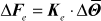
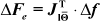
According to eq.(6), the stiffness of the specimen can be deduced by

with
where ‘
In a discrete-time control system, the stiffness can be estimated using successive samples with the following form:

with

However, the rough estimation method expressed by eq.(12) should not be put into practical use, simply because the differential action can easily be interfered with by environment noise. In this paper, a Forgetting Factor RLS method is used to make the stiffness estimation process stable and effective. The linear relationship between Δ

where
The estimation procedure is as follows:


where α > 0, 0<λi ≤ 1 and i = 1,2,…6.
4. Control design
The control strategy for the classic material-testing machine has been thoroughly studied [20, 26, 27]; however, none of the methods that have been established can be directly used for the proposed machine, which has six individual actuators. The two best-developed force control methods, position/force hybrid control and impedance control [15, 16], do not suit the parallel material-testing machine well because there is no explicit position input for the controller. For the proposed machine, the displacement of the moving platform is strongly dependent on the input force and the stiffness of the specimen, while the specimen stiffness, as mentioned in section 1, is not always a consistent value.
For the proposed material-testing machine, when performing material testing the moving platform moves passively according to the deformation of the specimen; furthermore, the exact mechanical properties of the specimen are always unknown. Since the only explicit inputs to the proposed machine are the active forces applied by the six actuators, a pure force-based adaptive control strategy is proposed in this paper. Additionally, a stiffness estimation method is also proposed and embedded in the control method in order to improve the performance of the controller.
Computed torque control has been extensively investigated for serial manipulators and it can be used in both joint space and task space. The dynamic interaction between the end-effector and the target object must be considered in the task space in order to obtain higher performances when designing force controllers for parallel robots[28], because performed tasks are usually defined in the task space. For the proposed machine depicted in Figure 1, no auxiliary sensor is mounted on the moving platform to measure the system state values in the task space. On the contrary, all the data used for the force controllers are obtained from those force sensors and motor encoders that are installed in the joint space. Consequently, a state estimator is essential to evaluate the system state in the task space using the measured data. In the state estimator, the generalized position is worked out using eq.(3), the generalized velocity is calculated by eq.(2), and the generalized acceleration is solved using the Newton-Euler method [28].
Since the typical PID control scheme is most commonly used in the industrial parallel robots, in this paper it is considered a fair benchmark to compare with the proposed adaptive force control scheme. The control blocks of the classic PID controller and the proposed adaptive controller are described in Figure 3 and Figure 4.

Classic PID control scheme
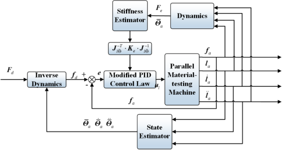
Adaptive PID force control scheme
In Figure 3 and Figure 4,
To lower the uncertainties of the proposed machine to an acceptable level, the geometric and inertial parameters of the mechanical system should be exactly measured before assembling. The desired actuation force can be derived by:

where
With reference to eq.(17), the desired actuation force

where Kp, Ki and Kd represent the proportional, integral and derivative coefficients, respectively.
Substituting eq.(9) into eq.(18), the adaptive control law can be obtained by rewriting eq.(18) in the following form:

where
Generally, eq.(19) works only when matrix is
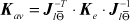
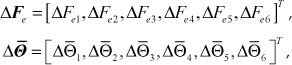
With reference to eq.(19), the proposed adaptive control law has adjustable parameters

where
5. Simulation tests
In this section, the classic PID control method and the proposed adaptive control method are both tested by a co-simulation platform composed of MATLAB/Simulink and ADAMS/Control modules. In the modelling stage, the prototype of the proposed loading mechanism, shown in Figure 1, is firstly constructed in ADAMS software in a simplified form and then exported and embedded in a MATTAB/Simulink module where the target control schemes are fabricated. The simulation flow chart is depicted in Figure 5.

Simulation flow chart
Two simulation tests are performed in this section. In the first case, the stiffness of the specimen is supposed to be a constant value in order to simulate a static testing process where a metallic specimen is elastic. Generally, for conventional static testing of metallic specimens, the stiffness changes sharply when the specimen material yields. So In the second case, a specimen with a variable stiffness is therefore studied in order to evaluate the feasibility of the proposed control scheme.
5.1 Fixed stiffness simulation
In this section, a tension-bending-torsion composite loading simulation test is performed. The schematic is shown in Figure 6. The stiffness of the flexible specimen is factitiously settled in a group of special values. Concretely, the axial stiffness along z direction is 2.0×10⁵N/mm, and the shear stiffness and the torsional stiffness are defined as 2.0×10⁷N.mm/°.

Schematic of a tension-bending-torsion loading case
To thoroughly test the performance of the proposed control scheme, square waves and triangle waves are adopted as input signals. The simulation results are shown in Figure 7. The forgetting factor used here is 0.98 in order to make the stiffness estimator immune to external noise. The frequencies of the input signals are arbitrarily selected and the simulation time is two seconds. As shown in Figure 7, the proposed control method works well with these two types of signals.

Simulation results according to different waveforms
As depicted in Figure 8 and Figure 9, the converging process of the estimated stiffness is finished within 0.05 seconds and the measured stiffness curves are mostly closed to the designed stiffness values, most of the time. The estimated stiffness curves fluctuate when the applied forces approach zero; however, those estimation errors, which are mostly less than 2% of the design values, exert negligible effects on the output forces. The relationship between the applied loads and their corresponding deformations are depicted in Figure 8(c) and Figure 8(d), which also demonstrate the stability of the stiffness estimation method.

Simulation results, (a) (b): estimated stiffness values in the simulation test using triangular waveform signals and (c) (d): load-deformation curves

Estimated stiffness errors in simulation test with triangle waves
The following errors are measured in the simulation tests with triangle waves, and the results are given in Figure 10. As shown in Figure 10, the following errors are mostly within 4% of the input design values and hence acceptable in practice. Furthermore, the proposed loading machine exhibits better performance along the compliant axis, where following error quantities are, on average, 67% of those about the y axis.
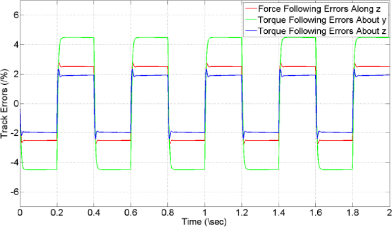
Following errors in simulation test with triangle waves
5.2 Variable stiffness simulation
Although the proposed machine works well with specimens with constant stiffness, the controller with fixed parameters will not perform as well when the specimen is replaced by another specimen of different material. In some other cases, the stiffness of the specimen will alter as the test proceeds, because of crack propagation or transition from linear elastic to plastic behaviour. The designed controller, even when properly tuned beforehand, will thereby become sluggish or instable over the operating cycle or after the material properties have changed.
In this section, the performance of the proposed adaptive control method is fully tested in simulation. Triangular waveform and sinusoidal waveform signals are adopted to prove the applicability of the proposed adaptive control method. Since the Stewart platform is capable of applying a six-dimensional force through its worktable, the loads exert on the specimen are planned as a series of six-component forces, as shown in Figure 11.

Schematic of a six-component force loading case
The classic PID control method and the proposed adaptive force control method are all examined with simulation tests. The two control methods use the same PID parameters, which are well tuned before the simulation tests. The stiffness of the specimen alters online to 10% of the original value between 0.7 s and 0.8 s of the simulation time. The simulation results are given in Figure 12–Figure 16.

Simulation results of sinusoidal waveforms
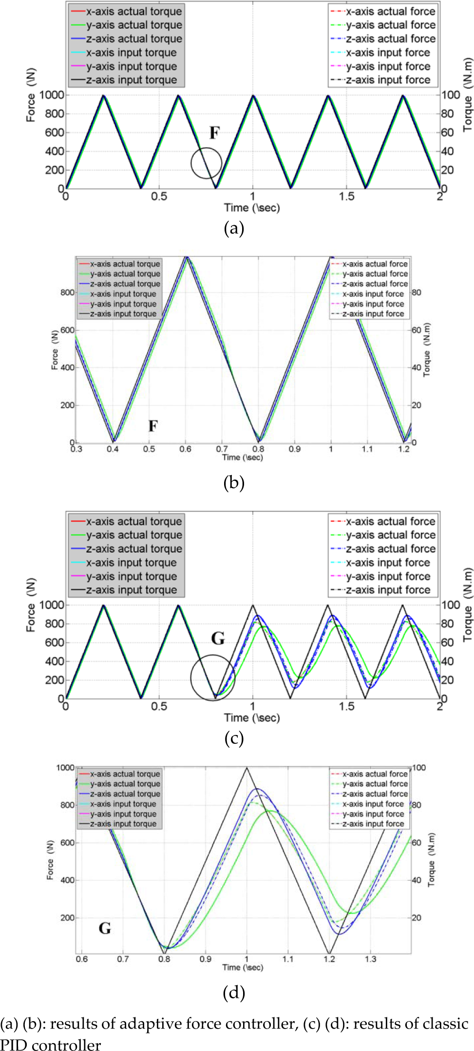
Simulation results of 2.5 Hz triangle waveforms
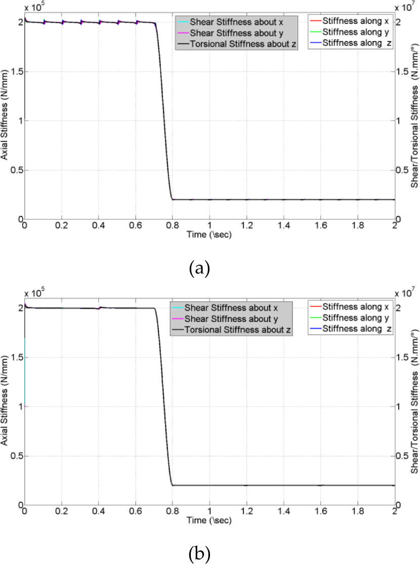
Estimated stiffness in the simulation tests of (a) sinusoid waves and (b) triangular waves
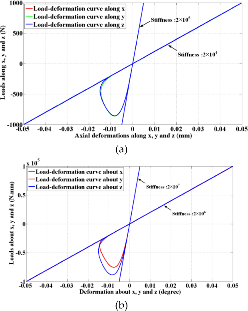
Load-deformation curves in the simulation tests of sinusoid waves

Adaptive tuning of the proportional gains in the simulation tests of (a) sinusoid waves and (b) triangular waves
As shown in Figure 12 and Figure 13 the output signals are in accordance with the input values in both the classic and adaptive PID control processes at the beginning of the tests. However, this correlation is broken up at a point shown in the plots corresponding to 0.7 s, where the specimen stiffness begins to change. The two control methods exhibit quite different behaviours according to the stiffness alterations. As depicted in Figure 12, Figure 13 and Figure 16, the proportional gains of the proposed adaptive control method are quickly increased to adapt to the stiffness changes, while the classic PID controller becomes sluggish and large following errors appear in the consequent test. As shown in Figure 14 and Figure 15, the alteration of the stiffness can be accurately identified and the load-deformation curves also attest to the validity of the proposed stiffness estimation method.
The stability of the proposed control scheme can also be validated by the simulation results. Responses to the rectangular inputs are described in detail in Figure 17, where the designed specimen stiffness begins to change at 0.7 s and the stiffness value is sharply lowered from 2.0×10⁵ N/mm (2.0×10⁷ N·mm/º) to 2.0×10⁴ N/mm (2.0×10⁶ N·mm/º), as depicted in Figure 14. As shown in Figure 17, the proposed controller can respond to the desired rectangular waves promptly and steadily both before and after the alteration of the specimen stiffness. Although overshoots exist in certain DOFs, they are quickly eliminated and the maximum overshoot is less than 5% of the input amplitude. Furthermore, the static errors are small enough to be ignored. Therefore, responses to rectangular waves can illustrate that the proposed control scheme is stable.

Responses to rectangular inputs in variable stiffness simulation tests
The following errors plotted in Figure 18 and Figure 19 also demonstrate the excellent performance of the adaptive controller. In simulation tests with the adaptive controller, the following errors are sharply increased between 0.7 s and 0.8 s, but are quickly reduced to the same levels as before the stiffness fluctuations. On the contrary, the classic PID controller cannot cope with the stiffness disturbances and the following errors are increased by more than five times. In addition, the following errors concerned with the complaint axis are usually smaller than those of other axes. The following errors depicted in Figure 18(a) and Figure 19(a) are all within an acceptable level, less than 5% of the input amplitude, which also proves that the stability of the adaptive controller is excellent.

Following errors in simulation tests with sinusoid waves using (a) adaptive controller and (b) classic PID controller

Following errors in simulation tests with triangle waves using (a) adaptive controller and (b) classic PID controller
In practice, the low-cycle fatigue (LCF) tests are usually conducted by triangular waveforms with sharp corners, which are necessary because vertex truncation introduces variability in predicted fatigue life. Hence, the control aim is to obtain fast strain reversal. In high-cycle fatigue (HCF) tests, moreover, the controller must maintain a high performance because performance reduction of the controller will lead to large track errors and extension of the experiment time.
Generally the classic PID controller with fixed control parameters cannot meet the requirements of the LCF and HCF tests, which is proven by the simulation results. On the contrary, the proposed adaptive control method, which is capable of self-tuning, can deal with the problems caused by online alternation of the specimen stiffness. The simulation results illustrate that the adaptive force controller method has good performance in executing both the LCF and the HCF tests.
6. Conclusion
In this paper, an adaptive force control method for a 6-DOF material-testing machine has been studied and tested by simulations. The mechanical model of the material-testing machine was established using the Kane method. The stiffness equivalent matrix was firstly deduced to represent the relationship between the driven forces and the displacement of the actuators, and then used in the stiffness estimation method, which is designed to evaluate the specimen stiffness online. The proposed adaptive control method, which is derived by combining the classic PID control law with the stiffness estimator, can adaptively adjust proportional gains of the controller according to the alternations of the specimen stiffness. The excellent control performance of the proposed control strategy is proven by simulations. The force control performance of the 6-DOF material-testing machine using both the classic PID controller and the adaptive controller is analysed for a virtual loading test with variable-stiffness specimens. The results illustrate that the adaptive force control scheme can quickly eliminate the negative effects stemming from the stiffness variance of the specimen, while the classic PID controller becomes sluggish and is no longer suitable for precise control. Moreover, it is found that the following errors are usually smaller in the directions concerned with the compliant axis. The possibility of using the proposed 6-DOF material-testing machine to perform LCF and HCF tests is also proven by the simulation results.
Our future research will focus on practical applications of the proposed material-testing machine and adaptive controller. Concretely, the target 6-DOF material-testing machine will be fabricated and the proposed adaptive control method will be validated through practical material testing.
Footnotes
7. Acknowledgement
This project is supported by the National Natural Science Foundation of China (Grant No. 51305013). The authors would like to thank the editor, associate editors and anonymous reviewers for their constructive comments.