
Abstract
6-DOF parallel robot always appears in the form of Stewart platform. It has been widely used in industry for the benefits such as strong structural stiffness, high movement accuracy and so on. Space docking technology makes higher requirements of motion accuracy and dynamic performance to the control method on 6-DOF parallel robot. In this paper, a hydraulic 6-DOF parallel robot was used to simulate the docking process. Based on this point, this paper gave a thorough study on the design of an adaptive controller to eliminate the asymmetric of controlled plant and uncertain load force interference. Takagi-Sugeno (T-S) fuzzy inference model was used to build the fuzzy adaptive controller. With T-S model, the controller directly imposes adaptive control signal on the plant to make sure that the output of plant could track the reference model output. The controller has simple structure and is easy to implement. Experiment results show that the controller can eliminate asymmetric and achieve good dynamic performance, and has good robustness to load interference.
1. Introduction
Space docking technology plays an important role in the field of manned spaceflight. Space docking mechanism is used to combine two spacecraft to a solid complex. Peripheral docking mechanism, whose actuation mechanisms are peripherally laid to make enough space for the central channel, was widely used in manned space areas of both Soviet Union and United States. Figure 1 shows the NASA Docking System, passive part on the left and active part on the right. The motion drive mechanism is a Stewart mechanism.

Mechanism of NASA Docking System
Stewart mechanism is now commonly used for 6-DOF parallel robot. Compared with classic serial mechanism, parallel mechanism has better stiffness, stronger carrying capacity, more stable structure and higher motion accuracy. Therefore, Stewart platform mechanism was commonly used in peripheral docking system, as in the NASA Docking System.
In this paper, a self-designed hydraulic 6-DOF parallel robot was used to simulate and study the motion features and control methods of space docking mechanism, as shown in Figure 2. Stewart platform mechanism is highly nonlinear, variable-loaded, and multi-parameter coupled. To develop the working space, the six rods of the platform are usually driven by asymmetrical cylinders, whose asymmetry would cause more control difficulties.

Hydraulic 6-DOF robot for docking simulation study
The motion control of parallel robot is separated to two branches: joint-space control and task-space control. Task-space control, which is based on forward kinematics and inverse dynamics, is more energy-efficient and has better dynamic control effects, but needs additional force, position or attitude sensors and better control processors for kinematics solver. The dynamics analysis is also a difficulty in this field. Joint-space control is more common to be used for its lower requirement of hardware. The controller design is based on how to make every hinge of motive point track predetermined trajectories, which can be solved out from the predetermined position and attitude trajectory of the motive platform. The difficulty of this method is to eliminate the unknown load force interference in every single control channel.
This paper gave a thorough study on the joint-space control method, using T-S fuzzy inference model to design a model reference adaptive controller. The model reference adaptive control method is based on measuring the output or/and status differences between reference model and controlled plant to make a control decision. It can well solve the problems mentioned above. Fuzzy inference method is fit for the process of the control decision to control such a nonlinear uncertain system. Compared with the traditional Mamdani fuzzy inference method, T-S fuzzy inference method is a more compact and computationally efficient representation, and works well with adaptive techniques.
2. Parallel Robot Mechanism Analysis
2.1 Mechanism structure
The kinematics mechanism sketch of Stewart platform is shown in Fig. 3. It is made up of a base, a motive platform, and six rods whose lengths are variable. Each rod is connected with base and motive platform via a universal joint. In practical application, the rods are realized commonly by cylinders, however, the universal joints are always replaced by spherical joints, such as in Figure 3, which would not increase the DOFs of motive platform, but only give cylinders and piston rods rotation DOFs along their self-axis. Decided by the lengths of six rods, the motive platform has six DOFs, three translation DOFs and three rotation DOFs.

Kinematics mechanism sketch of 6-DOF robot
2.2 Inverse Kinematics Analysis
In Fig. 4, define Oxyz as the coordination system (CS) of the base, and O'x'y'z' as the CS of the motive platform.
So the position and orientation of the motive platform in Oxyz can be present as a 6D vector (x, y, z, φx, φy, φz)T, and the position vector
Select any rod to analyze.

In (1),

In (2),
According to the vector relationship in Fig. 4,

Vector relationship sketch for single rod analysis

The position output of each rod pn can be presented like

In Eq. (4), ln0 is the median length of a rod.
For
3. Single channel modeling
In this paper, the space docking simulator is a hydraulic 6-DOF.parallel robot. Each rod is driven by a valve-controlled asymmetrical cylinder. The six channels have the same structure type.
3.1. Model of valve-controlled cylinder
The mechanism sketch of valve-controlled cylinder is shown in Figure 5. According to the load flow equation, flow continuity equation and load balance equation, ignoring the elastic load, piston displacement output model of valve-controlled cylinder is established as

Mechanism sketch of valve-controlled cylinder
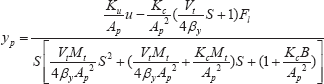
yp is piston displacement, u is valve drive voltage, Fl is load force, Ku is valve voltage – spool displacement amplification coefficient, Kc is valve flow – pressure amplification coefficient, Ap is piston effective area, Vt is cylinder equivalent total volume, Mt is load equivalent total mass, βy is equivalent volume elastic modulus, and B is piston motion damping coefficient.
3.2. Model simplification
In Eq. (8),

3.3. Actual parameter model
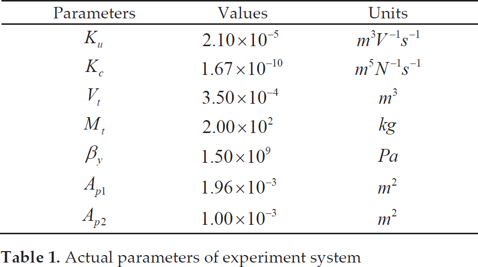
In the experiment system, the valves and cylinders are all from Atos. The input voltage of valve solenoid drive is ±10V. The piston stroke of the cylinder is 280mm. Setting the median of stoke as the initial position, the actual parameters of the experiment system are shown in Table 1. Ap1 is piston effective area of chamber without rod, and Ap2 be of chamber with rod.
Substituting the parameters into (6), the actual parameter model is shown in Table 1.
Actual parameters of experiment system
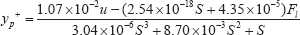

If the pressure oil go into the chamber without rod, u > 0, yp=yp+; else if u ≤ 0, yp=yp−.
Meanwhile, −10≤u≤10 and −0.14≤yp ≤0.14.
4. Design of T-S fuzzy adaptive controller
4.1. Control system structure
Considering that the control plant is nonlinear and the load force is variable, a model that meets the control requirement can be introduced to be the reference model to reduce the control difficulty and make the system more stable.
The structure of the control system is shown in Figure 6. e is the error signal between reference model output ym and plant output y. According to e and ė, the adaptive controller generates adaptive control signal uc. The adaptive controller is based on T-S fuzzy inference.
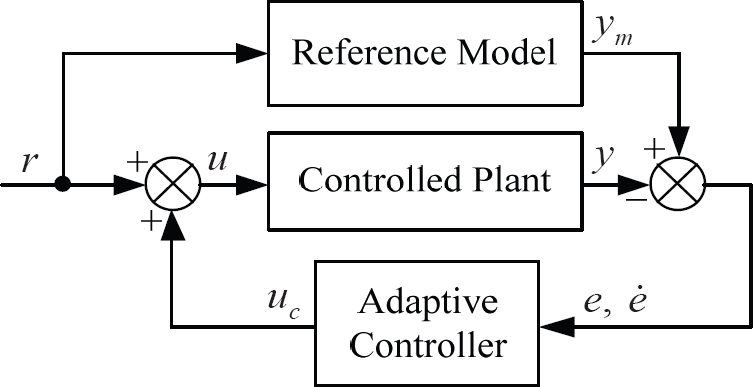
Block diagram of control system
4.2 T-S Fuzzy Adaptive Controller Design
The main difference between Mamdani and T-S fuzzy models is that the T-S output membership functions are linear expresses of input variables. The experimental results showed that it is enough only to linearly express e for the output to make a good control effect. This can effectively simplify the controller design. Figure 7 is the block diagram of the designed fuzzy inference system.

Block diagram of fussy inference system
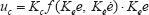
The adaptive control signal uc can be recorded as
Setting the domain of both Kee and Keė as [-6, 6]. Defining fuzzy subsets of Kee and Keė as {NB, NM, NS, NO, PO, PS, PM, PB} and {NB, NM, NS, O, PS, PM, PB}. Three types of membership functions were used as follows.
Triangular-shaped membership function

Z-shaped membership function
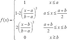
S-shaped membership function

The parameters of membership functions are in Table 2 and Table 3.
Membership function parameters of Kee

Membership function parameters of Kee

The input membership functions of Kee and Kee are shown in Figure 8 and Figure 9. The fuzzy sets ‘NO’ and ‘PO’ of Kee are specially designed in those shapes to increase the tracking accuracy and to reduce steady-state error.

Membership function of Kee

Membership function of Kėė
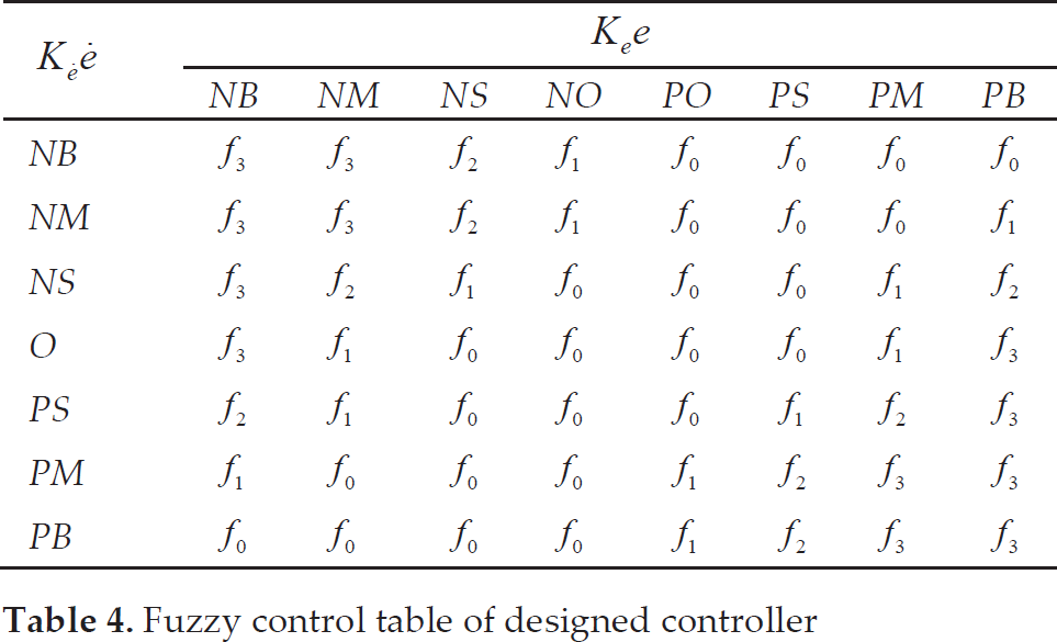
Choose f0=0, f1=0.3Kee, f2=0.6Kee, f3=Kee to establish the fuzzy inference table in Table 4. The design was according to the general control experience. The input-output relationship surface of the designed fuzzy system is in Figure 10.
Fuzzy control table of designed controller

Input-output relationship surface
By adjusting the scale factors Ke, Ke and quantization factor Kc, the model tracking capability of the system would be well improved. In fact, these parameters are associated with physical quantities. Therefore, it's easy for experienced engineers to adjust the parameters of the controller.
5. Simulation
A signal fuzzy controller based on the algorithm mentioned in Chapter 4 was established in Simulink®, with 1kHz sampling frequency, in order to lay a foundation for the hardware implementation of the controller. The fuzzy controller established in Simulink is shown in Figure 11.
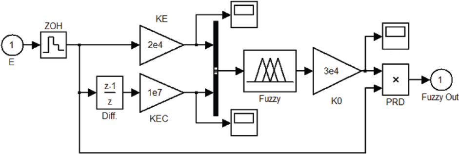
Fuzzy controller established in Simulink
According to the system requirement of dynamic performance, the reference model was chosen as
All the simulation results were compared with a PID controller tuned with Control System Toolbox of MATLAB®. In every curve figure, there are three curves: No.1 is the desired output response, No.2 is the output response controlled by the designed controller, and No.3 is the output response controlled by PID controller.
Figure 12 shows that the designed controller makes a good step response to meet the system requirement, with a setting time less than 0.8s, and the step response of PID controller has a shorter rise time but with overshoot and a longer setting time. The step responses from 1.5s to 2s in Figure 13 show the steady-state errors. The designed controller is less than 0.1%, and PID controller more than 0.7%.
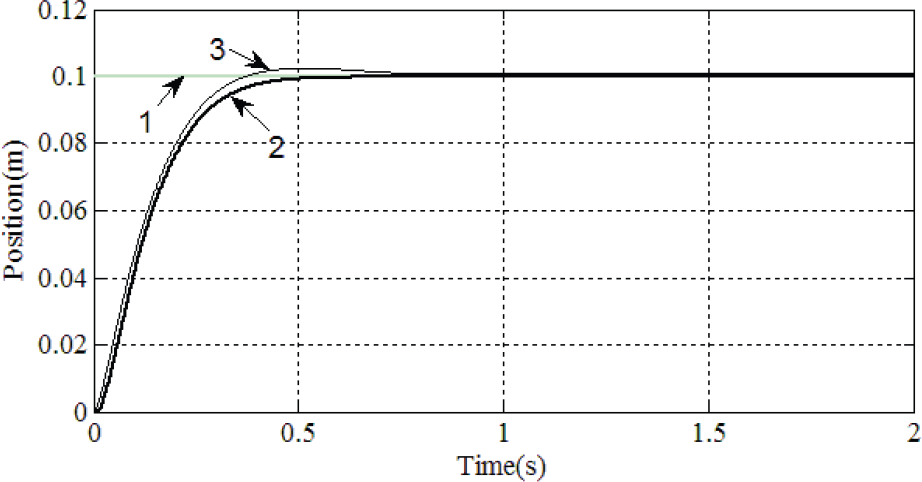
Step response curves

Steady-state errors comparison
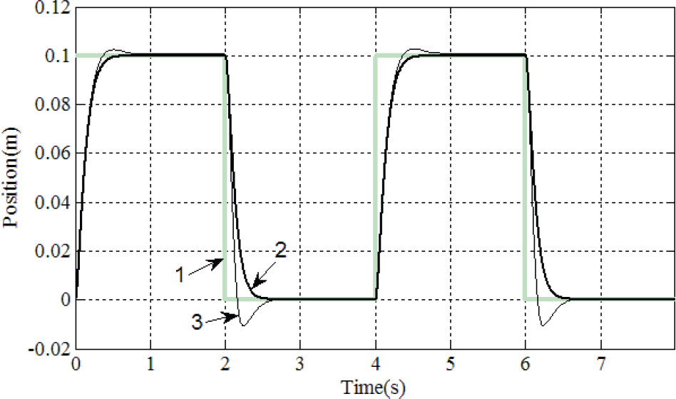
Square wave response curves
In Figure 14, the designed controller's square wave response shows a good symmetry, however, the response of PID controller is obviously asymmetrical, since one group of PID parameters cannot adapt to systems with different parameters. Sine wave responses in Figure 15 also illustrate this point.

Sine wave response curves
The curves in Figure 16 are gotten by adding a 2000N constant interference. The designed controller made a much better anti- interference ability than PID controller.
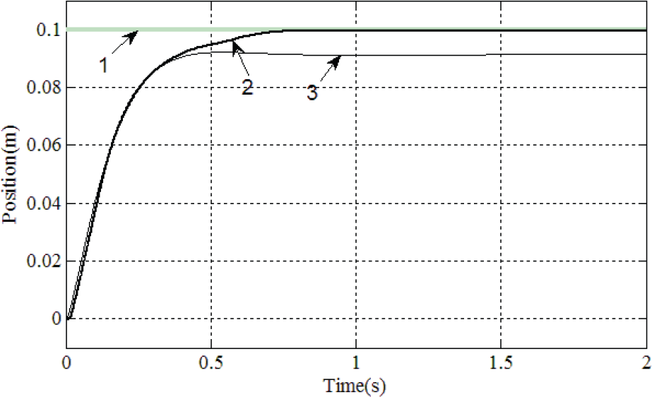
Step response curses under constant interference
Figure 17 shows a dynamic model of a parallel robot established with SimMechanics® of MATLab®. It's used to verify the feasibility of control algorithm for the platform. In simulation experiment, 1000kg centro-symmetric load was added on the motive platform. During the motion process of platform, uncertain load would be imposed on each channel.

Dynamic simulation model in SimMechanism
Using the analysis result of Chapter 2, the desired output of each channel can be solved when the desired trajectory of motive platform is given. One motion trajectory was selected to simulate a yaw motion along Z-axis with amplitude of 20° and frequency of 0.5Hz.
As the platform is centro-symmetric, the desired channel outputs are of two kinds, shown in Fig. 18 and Fig. 19. The figures prove that with uncertain load, the designed controller made a good dynamic tracking performance, as the PID controller was poor.

Desired response and actual outputs of Channel 1, 3, 5

Desired response and actual outputs of Channel 2, 4, 6
6. Experiments
6.1 Experiment System Introduction
The hydraulic 6-DOF parallel robot for experiments is shown in Figure 1, with six valve-controlled servo cylinders from ATOS®. The proportional valves receive +/-10V voltage signal, and the linear displacement sensors feed back 0∼10V voltage signal. The stroke of cylinders is 280mm.
The hydraulic oil source system, shown in Figure 20, is mainly made up of a constant pressure variable pump from Vickers® with 33mL maximum discharge capacity, and an AC motor from ABB® with 1440r/min rated rotation speed. The oil source system can provide maximum 47.5L/min flow.

Hydraulic oil source system for experiment
The hardware controller is an IPC from Advantech® with 16-bit multi-channel A/D and D/A cards. IntervalZero® RTX real time operation sub-system is used to ensure that the control algorithm programs can run reliably.
6.2 Experiment results analysis
Considering the flow supply ability of hydraulic oil source system, only minor and slower motions than those in simulations could be achieved. The working oil pressure was set to 7MPa.
Figure 21 shows the result of the experiment to apply a sine signal of 50mm amplitude and 0.25Hz frequency to each channel. Line 0 is the desired signal and Line 1–6 are the response curves. The response curves of different channels are almost overlapped. The tracking performance is satisfactory and the asymmetry problem is well solved. In fact, the controller parameters were adjusted with one channel and then used in other channels. This proves that the controller is not sensitive to the parameter differences of models.
The enlarged part of Figure 21 is in Figure 22, which shows that the maximum error among six curves is less than 0.5mm.

0.25Hz multi-channel sine wave curves

Enlarged part of Figure 21
In the next experiments, only one channel was enabled, and other channels were locked with zero strokes. During this experiment process, the motion of motive platform was more complex, and the load force from the motive platform to the controlled channel was changing obviously because of the inertia and reaction of motive platform.
To illustrate the character of the designed controller, a traditional PID controller was introduced for reference. In the figures of experiment results, Line 1 is the desired signal, Line 2 is the response curve of the designed controller, and Line 3 is that of a traditional PID controller.
In Figure 23, the curves show that the designed controller can well eliminate the asymmetry of controlled plant, which PID controller cannot achieve. The positive and negative step responses of designed controller show consistency. The variable load force to the rod can also worsen the dynamic response of PID controller, but the effect to the design controller is very small.
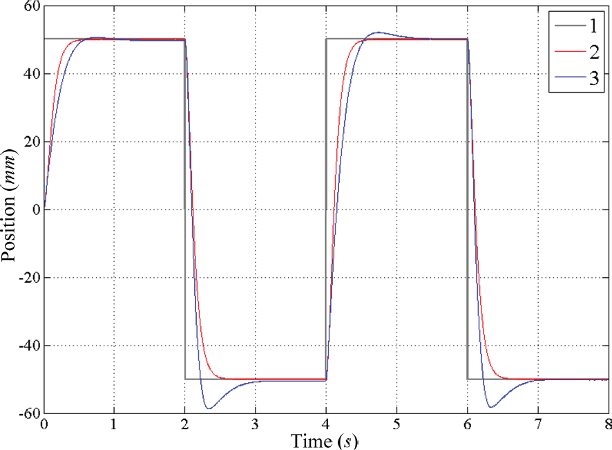
Single-channel square wave curves
Figure 24, Figure 25 and Figure 26 are the response curves under sine signals of 50mm amplitude and 0.25Hz frequency, 30mm amplitude and 0.5Hz frequency, and of 10mm amplitude and 2Hz frequency.

0.25Hz single-channel sine wave curves

0.5Hz single-channel sine wave curves

2Hz single-channel sine wave curves
In 0.25Hz response experiment, both the designed controller and PID controller can achieve satisfying tracking characteristics. The designed controller shows better consistency in different directions.
With the increasing of frequency, the differences of two controllers are more and more obvious. The designed controller continues to show good tracking characters. However, the PID controller cannot play well as in 0.25Hz experiment. The curves shift down obviously by the more significant effect of the dynamic load from motive platform inertia.
The comparative tests prove that the designed controller has a better robustness than the conventional PID controller, and can obviously eliminate the asymmetry of controlled plant.
7. Conclusions
The designed adaptive controller for 6-DOF Parallel robot can control the nonlinear system to obtain a good dynamic and tracking performance, and is effective on eliminating the asymmetry. This controller demands a low hardware requirement, and the control algorithm is simple and effective. The robustness of the controller is much better than traditional PID controller, and is not sensitive to the parameter differences of models. Therefore, the controller parameter adjustment would be more efficient. As the controller was designed as a 1 kHz digital controller, the experiment results also prove the feasibility of implementing the algorithm in hardware.
The work in this paper lays foundation for further studies of the space docking mechanism.
Footnotes
8. Acknowledgments
This work is supported by the China National Defense Fund on Key Discipline Construction (Fund Number: BHBKGW 1–2).