
Abstract
The adhering capability, one of the most important performance indexes of wall-climbing robots(WCRs), should be taken into account when a WCR is designed. This paper proposes a novel approach for investigating the adhering characteristics of the sliding suction cup (SSCs) using fluid network theory to enhance the adhering capability of WCRs. The fluid models of the SSCs of two WCRs are developed and equivalent circuits in three cases are presented. The dynamic responses of negative pressure in SSCs are obtained and validated by a set of experiments. It indicated that the theoretical analysis is reasonable and can give some valuable design criteria on the structure parameters of SSCs and control strategies of suction force of SSCs.
Introduction
The wall-climbing robots(WCRs) can replace human-beings to perform dangerous tasks such as inspecting, maintaining and cleaning in hostile environments (Manuel, A., 2003, Wang, Y., 1999, Guido, L.R., 2002, Zhu, J., 2002). The adhering capability, like the locomotion ability, is one of the most important performance indexes of WCRs. The negative pressure suction cups are widely used to help WCRs adhere to non-metal walls. Therefore, it is absolutely necessary to study the adhering characteristics of suction cups, including the reliably, the stability and the adaptability to complex wall surfaces, to enhance the adhering capability of WCRs. According to the number of the suction cup, it can be classed as single suction cup and multi-suction cups. Generally, the WCR with multi-suction cups adopted legged or crawling mechanism (Guido, L.R., 2002). For the WCRs with only one suction cup, wheeled mechanism is usually adapted and there is relative movement between the suction cup and the wall, called sliding suction cup(SSCs) (Nishi, A., 1996, Zhao, Y.Z, 2004, Miyake, T., 2003) because traditional suction cups cannot slide on the walls while staying attached. Owing to prominent merits of wheeled WCRs(WWCRs) and low complexity of the adhering structure, the SSCs may be the most promising approach for the development of WCRs (Schraft, R.D., 2003).
There had been many studies on the suction cups of WCRs. Most of them are focused on the stress analysis and the structure design. The design, kinetostatic and safety analysis of a WCR with two suction cups were presented when the WCR climbs from one surface to another surface (Bahr, B., 1996). The NINJA-1 had a VM (valve-regulated multiple) sucker which can provide suction force even if there are grooves and small differences in level of the wall (Hirose, S., 1991). A self-contained WCR with scanning type suction cups was developed with a manifold, a rotating cam and some small suction cups(Yano, T., 1997). It can guarantee that there is always a suction cup that can adhere to the wall surface with gaps. The ROMA2 used a pneumatically driven grasping mechanism with ten vacuum cups (Balaguer, C., 2002). A multifunction automated crawling system(MACS) for inspecting large aircraft external surfaces was developed (Backes, P.G., 1997). A set of specially designed short profile vacuum cups can make MACS move on surfaces with combined translational and rotational motion. It was affirmed that the SSCs may be the most promising hold system and a sealing unit was designed by pumping fluid into SSCs between contact surfaces to reduce the sliding friction and improve the sealing properties (Schraft, R.D., 2003). A self-adjusting multi-vacuum suction cup were presented and the work principle of the control switch was given (Jiang, H.Y., 1999).
However, to the authors' knowledge, no study has been done on negative pressure suction cups on the basis of fluid characteristics. A major motivation for this work is to present a novel approach to investigate the adhering characteristics of SSCs using fluid network theory in order to enhance the adhering capability of the WCRs.
Nomenclature
flow resistance(1 / m · s), m =1, 2, 3, 4
flow capacitance (m · s2)
fluid mass flux(Kg / s)
air pressure at the inlet and outlet of pipeline(Pa), respectively
average pressure(Pa), p̅ = (p1 + p2)/2
pressure difference(Pa), Δp = p1 – p2
negative pressure in SSCs (Pa)
standard air pressure(Pa)
maximum vacuum degree of the vacuum pump(Pa)
fluidic mass in SSCs (Kg)
capacity of SSCs(m3)
absolute temperature of gas(K)
flow inductance(1/m)
air pressure at the outlet port of the vacuum pump, the specific weight of air at the outlet and the velocity of air at the outlet port, respectively
height of the inlet/outlet port above the ground level, respectively, equal to zero
internal pressure of the SSCs at the inlet, the specific weight of air at the inlet and the velocity o air at the inlet, respectively.
gravitational acceleration
pressure loss due to the structure of gas pipeline system, e.g. shape discontinuity and valves.
air pressure pi in the air chamber
pretightening force of twleve regulating springs
effective sealing area of the SSCs(m2)
flow velocity(m / s)
coordinate direction
viscosity coefficient(kg / ms)
pressure intensity(N)
external and inner diameter of the air spring around the suction cup(m), respectively
gap between the air spring and the wall surface(m)
constant of gas, Rg =287 m2 / s2 · k
power of vacuum pump(w)
working voltage of the vacuum pump
efficiency of the vacuum pump
average density air (Kg / m3)
equivalent diameter of a gap(m)
height of the SSCs (m)
time constant, m =1, 2, 3
assurance coefficient (non-dimensional quantity)
This paper is organized as follows: Fluid network theory is introduced in Section 2. The fluid models of the SSCs of two WCRs are developed in Section 3. Section 4 gives the analysis of equivalent circuits in three cases. In Section 5, experiments are presented to verify the theoretical analysis and Section 6 contains the discussion. Conclusions are given in Section 7.
Introduction to fluid network theory
Fluid network theory is an applied science that develops with the study on fluidic transmission and transient in fluid pipelines (Foster, K., 1970, Roth, A., 1982, Luo, Z.C., 1988). The theory can be used to analyze the transmission process of power and information in fluid pipelines of industrial power settings, control survey devices and biomedicine engineering. Moreover, transient phenomena owing to disturbances can be analyzed. The theory is mainly involved with two academic subjects: one is the hydrodynamics; the other is the electricity network and transmission-line theory. In electricity, electrical properties are characterized by three basic parameters: resistance, capacitance and inductance. Similarly, properties of fluid flow are also characterized as flow resistance, flow capacitance and flow inductance. In addition, the pressure difference is corresponding to the voltage and the fluidic flux to the current.
Basic parameters of fluid flow(Luo, Z.C., 1988)
Flow resistance
The resistance to fluid flow due to fluid adhesiveness can induce energy loss. The flow resistance Rm is defined as the ratio of pressure difference Δp between both ends of the gas pipeline to fluid mass flux Qm through the pipeline:

The compressibility of gas is much apparent in comparison with the liquid. But gas can only approximately be regarded as incompressible fluid when there is little change of density. Any container with compressible fluid has fluid flux that is related with its capacity. The increase of air pressure will lead to the increase of fluid mass, i.e., there will be a convergence of fluid mass in the container. The flow capacitance Cm is defined as the ratio of the differential of fluid mass ϱ***M caused by pressure change to the differential of pressure change ϱ***p:
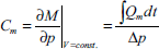
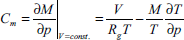
The state law of ideal gas pV = MRgT turns to, Vϱp + pϱV = RgTϱM + MRgϱT by differential, where p is the air pressure (Pa), V is the capacity of container (m3), Rg is the constant of gas and T is the absolute temperature of gas(K). Assuming that the capacity of the container is a constant, we can obtain:
The flow capacitance represents a physical quantity of the compressibility of fluid, which is relative to the frequency of pressure change and can be neglected under steady state or low frequency. But the flow capacitance must be taken into account in the process of fluid transmission and transient when the fluid flow works in the form of sine or step perturbation wave with constant frequency or changes with the time. From the point of view of power, the flow capacitance transforms the kinetic energy of gas to potential energy and stores, which is similar to that the capacitance transforms external energy to field energy and stores.
Pressure change may be caused by fluid inertia when quick-speed transient flow happens in fluid pipeline systems. The flow inductance Lm is defined as the ratio of pressure change to flow mass change in pipelines,

The flow inductance denotes that physical quantity that converts potential energy to kinetic energy and stores.
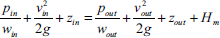
Commonly, vacuum pumps are used to develop negative pressure in SSCs with the help of the sealing unit and the gas pipeline system. Inevitably, the specific structure of the gas pipeline system of SSCs influences greatly the adhering capability of WCRs. Based on hydrodynamics, the Bernoulli equation of the gas pipeline system of SSCs can be obtained at the cross section of the vacuum pump (air outlet) and the contact section of SSCs with the wall surface(air inlet):
In a word, above working parameters can influence the adhering characteristics of the SSCs.
Example I: single SSC of a WWCR
The structure of single SSC
Due to simple structure, high moving speed, dexterous movement and convenient control, one of the authors had presented a WWCR for cleaning glass-curtain walls (see Fig.1) (Zhao, Y.Z., 2004). The driven wheels are placed in single big round SSC which is composed of a vacuum pump that is placed directly connected the SSC, a sealing unit and a body. An air spring, which is fixed around the body, is used as the sealing unit that consists of an air chamber, twelve regulating springs, an outer coating, a guide pole and a holddown(see Fig.2). The air chamber is used to make the sealing unit adapt accidented surfaces to some extend. The outer coating is made up of composite materials with good wearability and low friction coefficient. Above the air chamber, twelve regulating springs are mounted to offer appropriate pressure in the air chamber to ensure reliable seal. The pretightening force Ps of twleve regulating springs can be adjusted manually.

Picture of the WWCR

The sketch of the air spring of the single
Suppose that the gas flow is regarded as radial flow and axisymmetric radius-wise between the single SSC and the surface, the flow velocity u is the function of y and the Poisson differential equation can be expressed as follows:


The vacuum pump is considered as a pressure source, and its maximum vacuum is p–1 (equal to pout). The flow resistance R2 of the vacuum pump can be induced by


The flow inductance can be neglected due to low-frequency air flow in the SSC.
The fluid model of the single SSC is presented in Fig.3(a). Suppose that the wall is an ideal smooth surface, air absorbed through the gap between the sealing unit and the wall surface is equal to that drawn from the SSC by the vacuum pump. Therefore, gas flow will keep steady if there is no sudden large air leakage. The adhering characteristics studied by us are mainly related to dynamic transformational process of gas pressure in SSCs, i.e., the state transition due to pressure change is considered when the vacuum pump is turned on, turned off or when the SSC meets gaps. The flow state and the pressure distribution are not investigated here. Assuming that the air pressure in the SSC is larger than 1330 Pa (verified by experiments), the flow state can be regarded as laminar flow due to low vacuum degree.

Fluid models of the SSCs of two robots
Tether supported WCRs for cleaning flat glass-curtain walls have been developed recently (see Fig.4)[Qian, Z.Y., 2006]. The WCRs have no locomotion mechanism, but it can move on flat glass surfaces depending on the gravity and the lifting force of the windlass while staying attached. Moreover, it can cross horizontal window frame using dual SSCs by adhering alternately. The beauty of these robots is the simplicity, low cost and high payload compared with others although they have limited locomotion capability. The adhering mechanism, composed of two large rectangle SSCs, a common “H” type negative pressure occurring chamber and two vacuum pumps, enables the robots to adhere to the wall. The sealing unit (rubber strip) is simplied due to tethered locomotion and the ideal cross-sectional sealing model is given in Fig.5. Similarly, The fluid model of dual SSCs is shown in Fig.3(b), R′1, R′2, R′3 and R4 are the flow resistances derived from the contact surface between the SSCs and the wall, the vacuum pump, the gaps and the pressure loss in common chamber due to specific structure of the dual SSCs, respectively. The flow capacitance C′ m is also equal to V′ / RgT and the flow inductance is also neglected, where V′ is the capacity of the closed chamber.

Picture of a tether supported WCR in field

Ideal model of sealing unit of tether supported WCRs
The vacuum pump is suddenly turned on
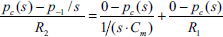
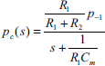
The equivalent circuit of the single SSC of the WWCR when the vacuum pump is suddenly turned on is presented in Fig.6(a). p–1 is regarded as the step-input of the single SSC and the standard air pressure P0 is supposed to be the datum. According to the linear circuit transient analysis theory, when t = 0+,


Equivalent circuits when the vacuum pump is turned on
By Laplace transformation,


Similarly, the equivalent circuit of the dual SSCs of the tether supported WCRs is presented in Fig.6(b) and the dynamic response is:

In practice, the wall is not an ideal smooth surface without any gaps. The equivalent circuit of the single SSC when the WWCR meets a gap is showed in Fig. 7(a). Assuming that pc keeps steady before meeting the gap when t = 0−, the initial parameters are:


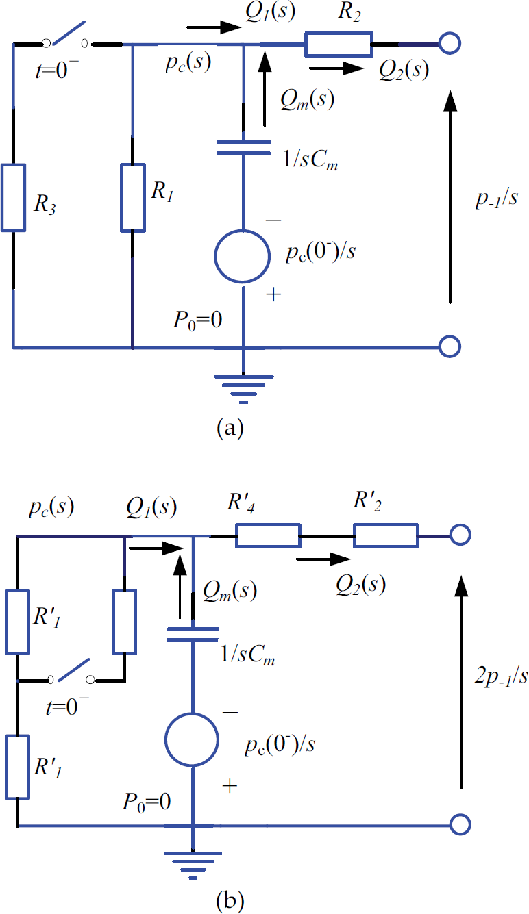
Equivalent circuits when two WCRs meet a gap
After rearrangement,

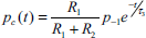
By Laplace inverse transformation, we can obtain the dynamic response of pc of the first fluid model:

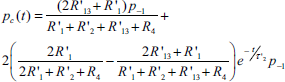
Similarly, the equivalent circuit of the dual SSCs when tethered WCRs meet a gap is presented in Fig.7(b) and the dynamic response of pc is:
The equivalent circuit of the single SSC is presented in Fig.8(a) when the vacuum pump is suddenly turned off. When t = 0−, the initial parameters are:

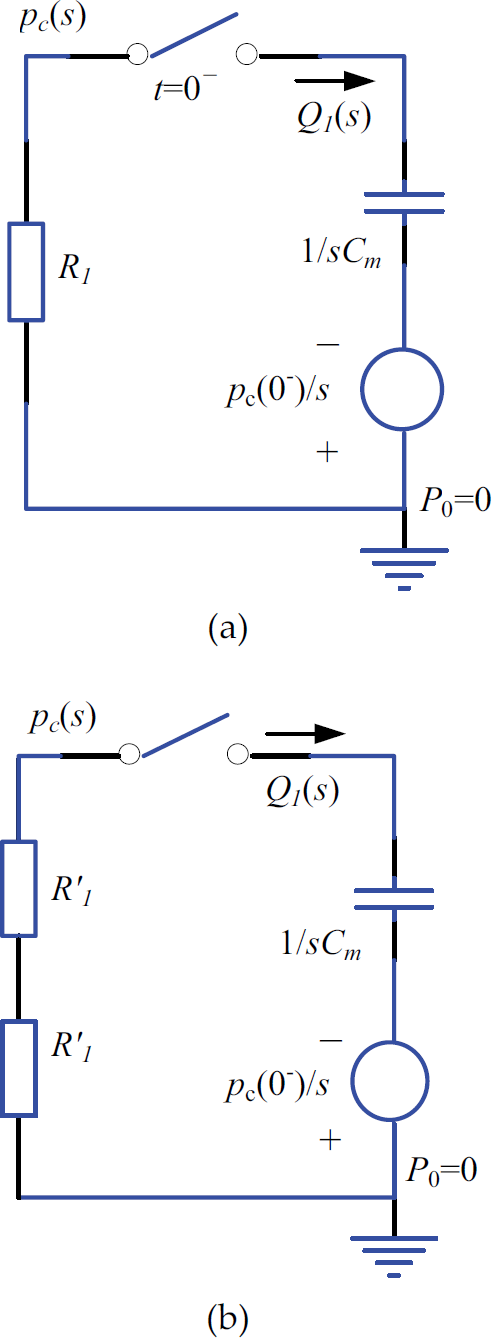
Equivalent circuits when the vacuum pump is turned off
After rearrangement, Eq.(22) turns to:
By Laplace inverse transformation, the dynamic response of pc can be formulated as
Similarly the equivalent circuit of the dual SSCs is presented in Fig.8(b) and the dynamic response of is:

To verify the theoretical analysis, a set of experiments were performed aiming at the single SSC of the WWCR. The experimental devices mainly consist of a vacuum pump, a SSC, a voltage regulator, a negative pressure sensor, an oscilloscope and a computer (see Fig.9).
Experimental devices The dynamic responses of pc corresponding to different amount of working voltage U (see Fig. 10) By regulating U, the running parameters of the vacuum pump(p–1, W, R2 and ζ) can be changed and pc can be subsequently changed. When the vacuum pump is suddenly turned on or off, the dynamic response curves of pc are shown in Fig.10. The amount of U can determine the end value of pc, but cannot change the dynamic response time. The dynamic responses of pc corresponding to different amout of air pressure pi (see Fig.11) By regulating the pretightening force of twelve regulating springs, pi changes and leads to the increase of the deforming height of the air chamber accompanied with different amount of A and δ. After that, the seal performance can be improved and R1 becomes larger accompanied with the increase of pi. When U = 215V and pi =0.013 MPa and 0.017 MPa, respectively, the dynamic response curves of pc are shown in Fig. 11. The dynamic responses of pc when the SSC meets different-sized gaps (see Fig.12)

Dynamic response curves under different amout of U when the vacuum pump are turned on or turned off
Responses curves under different amount of air pressure pi in the air chamber
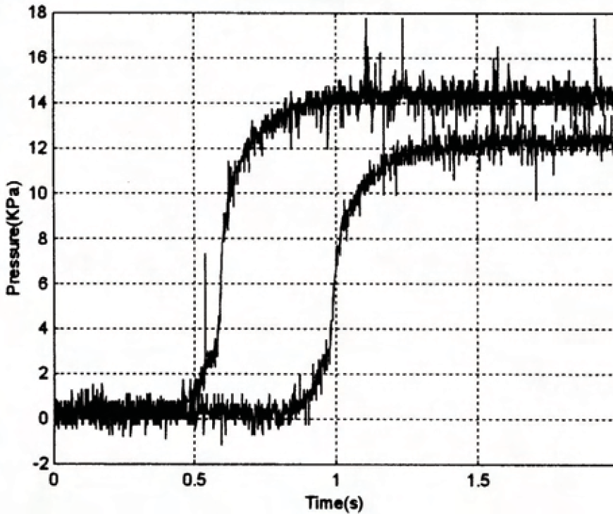
Response curves when meeting different-sized gaps on the wall
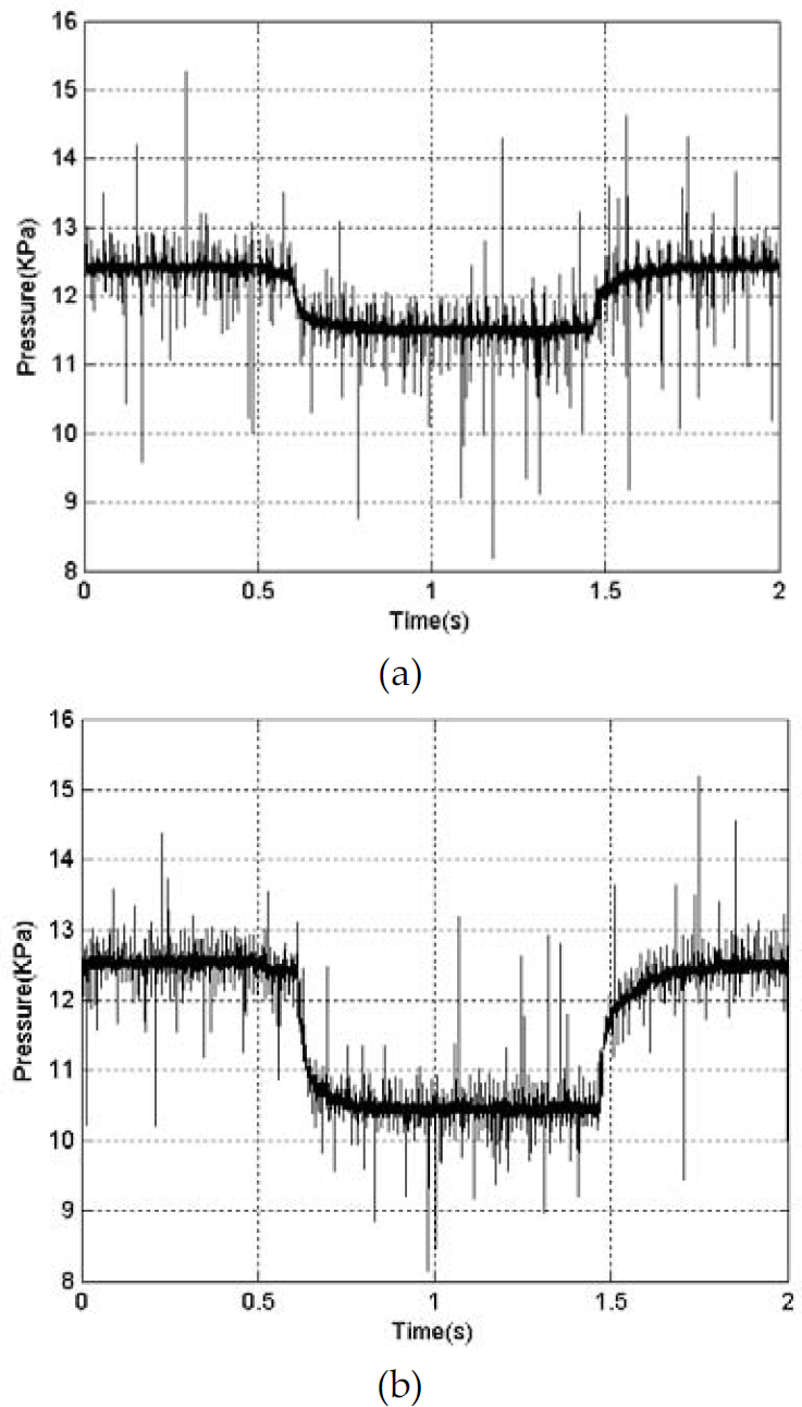
Gaps on the wall surfaces will lead to excess air leakage of the SSCs. Due to the limitation of experimental conditions, man-made holes on the single SSC are used to denote different amount of R3. The response curves when the SSC meets two and four 6 mm holes are shown in Fig.12, respectively. When U =215 V and pi =0.017 MPa, a set of actual parameters are: V =0.157 m3, A =0.25 m2, r1 =0.54 m, r2 =0.47 m, δ =0.43 × 10⁻⁶ m, P0 =1.013 × 10⁵ Pa, pc =1.4 × 10⁴ Pa, ρ =1.2 Kg / m3, μ =162.2 × 10⁶Kg / ms, D =0.006 m, W =1000 w, T =313 K and p–1 =2 × 10⁴ Pa. By calculation, τ1 =0.13 s, τ2 =0.11 s, τ3 =0.45 s, R1 =2.57 × 10⁵ 1/ms, R2 =1.05 × 10⁵ 1/ms, R3 =1.62 × 10⁵ 1/ms and Cm =1.75 × 10⁻⁶ms2. Therefore, the simulation dynamic response curves presented in Fig.13 can be also derived from Eqs.(16) (21) and (25). Compared with those in Fig.10–12, the analysis using fluid network theory is reasonable.
Response curves based on theoretical analysis
when the vacuum pump is turned on
By investigating the fluid characteristics of the SSCs of WCRs based on the fluid models, some design criteria of the structure parameters of the SSCs can be obtained. Moreover, some control strategies of the suction force of SSCs(equal to the product of pc and A) to increase the adaptability to complex wall surfaces are gained.
From the point of view of the structure design of the SSCs, the WCRs are generally expected to adhere to the wall reliably as soon as possible when the vacuum pump is turned on (namely, τ1(τ′1) is expected to be as small as possible). At the meantime, the decay time of pc can be as long as possible when SSCs are being on excess leakage (namely, τ3(τ′3) is expected to be as large as possible).
According to Eqs.(15) and (16), when R1 keeps constant, the vacuum pump should be fixed directly on the SSC like the WWCR, so that R2 and R4 can be reduced to shorten τ1(τ′1). If R2/R1 1, R = R2 and τ1 = R2Cm, the influence of R2 on τ1 is so significant that W and ζ should be as large as possible to decrease R2. Certainly, the selection of running parameters of the vacuum pump is restricted in practice. According to Eqs.(15) (24) and (25), R1 should be increased to decrease τ1(τ′1) and τ3(τ′3) at the same time. Therefore, the sealing performances of the SSCs should be enhanced, e.g. by increasing the width of the air spring to increase the ratio of r1 / r2, heightening the amount of pi of the WWCR or making more deformation of the rubber strip of the tethered WCRs. But, the good seal of SSCs may induce high friction coefficient and the increase of the driving force because minimizing both the leakage and the friction between two solid surfaces at the same time is an antagonism. In all, an appropriate amount of R1 is necessary. Cm plays an important role on the dynamic response time. In general, h should be small enough to reduce Cm when A is a constant according to Eq.(11), which can obtain lightweight structure of the SSCs. But, small amount of Cm may lead to the decrease of τ3(τ′3) and weaken the reliably of the SSCs when the SSCs encounters sudden excess air leakage. According to Eqs.(20) and (21), when t = 0+, pc remains inalterable. But, pc will decrease to a certain value due to R3 when t = ∞. It's certain that the WCRs can adapt definite large air leakage and cannot fall down so long as there is no excess air leakage on the SSCs. But WCRs may fall down when pc decreases to a certain critical pressure that is defined as Pd = Kcp–1. Therefore, the critical condition that WCRs attached to the wall reliably is pc(t = ∞)/p–1 ≥ Kc, where Kc is the assurance coefficient and should be appropriately determined. Accordingly, the allowable maximal amount of D of the gap can be determined.
In all, the flow resistance and the flow capacitance are important structure parameters of SSCs and have great effects on pc. Therefore, the structure, the sealing style and the material of SSCs and the running parameters of the vacuum pump should be appropriately determined when a WCR is being designed.
From the point of view of the control strategies of the suction force, and it is very important to guarantee the adhering capability when excess air leakage occurs and the structure of the SSCs has been determined. In fact, the suction force of the SSCs is neither too large, nor too small. It cannot be accepted if the suction force is so large that the WCR cannot move on the wall due to limited driving force. On the other hand, the suction force is so small that the WCR cannot adhere to the wall reliably. According to the dynamic responses of pc in many cases by investigating fluid characteristics of the SSCs based on fluid network theory, the control system transfer function of SSCs can be obtained. It is very helpful to offer a reference for regulating and improving the response speed of the control system, and further to eliminate the influence of instability of the negative pressure in the SSCs. Therefore, to offer appropriate and steady suction force, a close-loop control system should be adopted to generate, regulate and stabilize the negative pressure for reliable movement and good adaptability to complex wall surfaces by adjusting the working voltage of vacuum pumps. In this way, the working state of the WCRs can be maintained when the WCRs encounter external disturbances such as unpredictable air leakage due to different-sized gaps or silicone sealants, potential inactivation of the sealing unit and unsteady supply voltage.
In this paper, a novel approach has been developed to investigate the adhering characteristics of the SSCs of WCRs based on fluid network theory. The fluid models of SSCs of two WCRs are given. The equivalent circuits and the dynamic responses of negative pressure in three cases are presented. Compared with experimental results, the analytical method is proved to be reasonable. Some design criteria on the structure parameters of the SSCs for improving the adhering capability of the SSCs are obtained. Moreover, control strategies of the suction force of the SSCs can improve the adaptability to complex wall surfaces when the structure parameters of SSCs have been determined. Further research may be concentrated on the investigation on the optimization of structure parameters of the SSCs and the intelligent control system of suction force of the SSCs.