
Abstract
In this study, an exoskeleton type robot-assisted rehabilitation system, called RehabRoby, is developed for rehabilitation purposes. A control architecture, which contains a high-level controller and a low-level controller, is designed so that RehabRoby can complete the given rehabilitation task in a desired and safe manner. A hybrid system modelling technique is used for the high-level controller. An admittance control with an inner robust position control loop is used for the low-level control of the RehabRoby. Real-time experiments are performed to evaluate the control architecture of the robot-assisted rehabilitation system, RehabRoby. Furthermore, the usability of RehabRoby is evaluated.
Keywords
1. Introduction
The annual incidence of strokes is 15 million worldwide; one third of these patients die and one third experience permanent disability [1]. The incidence of this disease is steadily increasing along with the ageing of the population [2]. According to the World Health Organization (WHO), by 2050 the proportion of persons over 65 years old will have increased by more than 70% in industrialized countries and by more than 200% worldwide [3]. The population of Turkey is approximately 70 million, and almost 5 million are over 65 years of age [4]. Hemiparesis/hemiplegia is the most common outcome of a stroke and the main characteristics observed in hemiparetic patients are: weakness of specific muscles, abnormal muscle tone, abnormal postural adjustments, lack of mobility, incorrect timing of components within a pattern, abnormal movement synergies, loss of interjoint coordination and loss of sensation [5].
The aim of rehabilitation in hemiplegic subjects is to promote the recovery of lost functions, to provide independence and help ensure early reintegration into social and domestic life. Traditional treatments rely on the use of physiotherapy and on the therapist's experience [6]. The availability of such therapy programs, however, is limited by a number of factors such as the amount of costly therapist's time they involve, and the ability of the therapist to provide controlled, quantifiable, and easily replicable assistance for complex movements. Consequently, robot-assisted rehabilitation that can quantitatively monitor and adapt to a patient's progress, and ensure consistency during rehabilitation may provide a solution to these problems, and has become an active area of research [7–14].
Robot-assisted rehabilitation systems were first used in large scaled clinical tests in 1998 and since then several robot-aided rehabilitation systems have been developed [7]-[14]. There are two kinds of robot-assisted rehabilitation systems for the upper extremities in terms of mechanical design, which are end-effector-based, and exoskeleton type rehabilitation robots. MIT-MANUS [7], MIME [8], GENTLE/S [9] and NeReBot are end-effector-based, and AEMin [10], T-WREX [11], Pneu-WREX [12], L-Exos [13] and Salford Rehabilitation Exoskeleton [14] are exoskeleton type robot-assisted rehabilitation systems. Exoskeleton type robots resemble the anatomy of the human arm and each of the robot's joints can be controlled separately, which reduces the complexity of issuing controls. In this study, an exoskeleton type upper-extremity robot-assisted rehabilitation system, which is called RehabRoby, has been developed. RehabRoby has been designed in such a way that i) it can implement passive mode therapy, active-assisted mode therapy and resistive mode therapy, ii) it can be easily adjusted for people of different heights and with different arm lengths, and iii) it can be used for both right and left arm rehabilitation. Note that RehabRoby provides assistance to the subject in both active-assisted and resistive mode therapies when the force applied by the subject is not enough to track the desired rehabilitation task.
Controlling RehabRoby safely and in the desired manner is also an important issue. Impedance control [7],[10],[15], position control [8], [16], [17]and admittance control [9],[10] have previously been used to control robot-assisted rehabilitation systems. Various robotic therapy control algorithms that are intended to promote neuroplasticity and motor learning during rehabilitation after neurologic injury are reviewed extensively in [18]. There is a human-robot interaction in the robot-assisted rehabilitation systems, which is an external effect that can cause changes in the dynamics of the robotic systems. The changes in the dynamics of the robot may result in instability, which may affect the tracking performance of the robot. Therefore, a controller which is independent of the dynamic model of the robot-assisted system is needed for RehabRoby to compensate for changes in the dynamics of the robotic system [15]. In this study admittance control with an inner robust position control loop is used for RehabRoby to complete rehabilitation tasks in a desired manner. Note that it is also desirable for a patient to perform the rehabilitation task in a safe manner. Thus, a high-level controller, which is a decision-making mechanism, is designed to ensure safety during the execution of the rehabilitation task. The high-level controller plays the role of a human supervisor (therapist) who would otherwise monitor the task and assess whether the rehabilitation task needs to be updated. RehabRoby differs from similar rehabilitation systems due to its hybrid control structure that includes a robust position controller and a decision-making mechanism in the form of state machines.
RehabRoby was evaluated using healthy subjects. Subjects were asked to perform two well-known rehabilitation tasks (reaching chest to do up buttons, and reaching mouth to eat) with RehabRoby in active-assisted mode therapy and resistive mode therapy. This assessment may provide us with indications as to how RehabRoby and its control architecture can be used in the upper-extremity rehabilitation of stroke patients in different therapy modes. Additionally, we aim to evaluate the usability of the RehabRoby.
2. Methods
2.1 Control Architecture
A control architecture, which consists of a robot-assisted rehabilitation system, RehabRoby, a low-level controller and a high-level controller, and a sensory information module, is developed to respond to therapists' decisions, to decide on the plan of action, and to provide assistance to subjects in completing a rehabilitation task (Figure 1) [19–22].
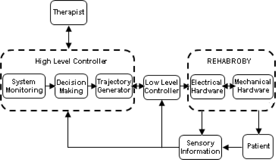
Control Architecture of the RehabRoby
2.2 Apparatus-RehabRoby
RehabRoby is designed to provide extension, flexion, abduction, adduction, rotation, pronation and supination upper-extremity movements and the combinations of these movements that are necessary for the tasks and activities of daily living (Figure 2-Left).

RehabRoby's Axes, (θ1: Horizontal abduction/adduction of Shoulder Rotation, θ2: Shoulder Flexion/Extension Elevation, θ3: Internal and External Rotation of Shoulder, θ4: Elbow Flexion/Extension, θ5: Lower Arm Elbow Pronation/Supination, θ6: Wrist Flexion/Extension),
Range of motion (ROM), joint torques, velocities and accelerations for RehabRoby were determined using the measurements of the movements of a healthy subject carrying out two tasks of daily life [10]. Higher values than those given in [10] were selected to ensure RehabRoby is strong enough to overcome the resistance of patients resulting from spasms (Table 1). There is a coupling between the flexion/extension and abduction/adduction of the shoulder. When θ1 is 0°, then θ2 is responsible for the flexion/extension of the shoulder, and when θ1 is 900, θ2 is responsible for the abduction/adduction of the shoulder.
Motion Specifications of RehabRoby

An arm splint, which has humeral and forearm thermoplastic supports with Velcro straps and a single axis free elbow joint, was designed and attached to RehabRoby (Figure 2-Middle). The thermoplastic arm splint designed for the RehabRoby has humeral and forearm supports with Velcro straps, and a thermoplastic inner layer that is covered by a soft material (Plastazote®). Two force sensors (Kistler - 9313AA1; Kistler France, Les Ulis, France) are placed in the inner surface of the plate attached dorsally to the forearm splint (Figure 2-Right). One of the force sensors measures the force applied during the elbow flexion movement and the other measures the force applied during the shoulder flexion movement.
Ensuring the safety of the subject is a critical issue for a robot-assisted rehabilitation system. Thus, in the event of an emergency situation, the therapist can press an emergency button to stop the RehabRoby (Figure 2-Middle), and the motor drivers of RehabRoby are disabled separately or together by pressing the driver enable/disable buttons without turning off RehabRoby. The system is powered by an uninterruptible power supply, thus, there can be no power loss and RehabRoby will not collapse at any time. Additionally, the joint angles of RehabRoby are monitored during the task execution.
RehabRoby can be easily adjusted for people of different heights and arm lengths (Figure 3). The link lengths of RehabRoby are based on the arm lengths of 2,100 people in 14 different cities in Turkey[23]. L1, which is the adjustable upper arm length value, varies from 260mm to 400mm, and L2 which is the adjustable lower arm length value, varies from 200mm to 300mm (Figure 3-Left). RehabRoby's height (L3) can be adjusted for each subject using a manually operated wheel (Figure 3-Right). RehabRoby can also be used for both right and left arm rehabilitation. Furthermore, RehabRoby is integrated with a counterweight mechanism to reduce the gravity effect to help subjects flex their shoulders more easily (Figure 4).

Adjustable Link Lengths
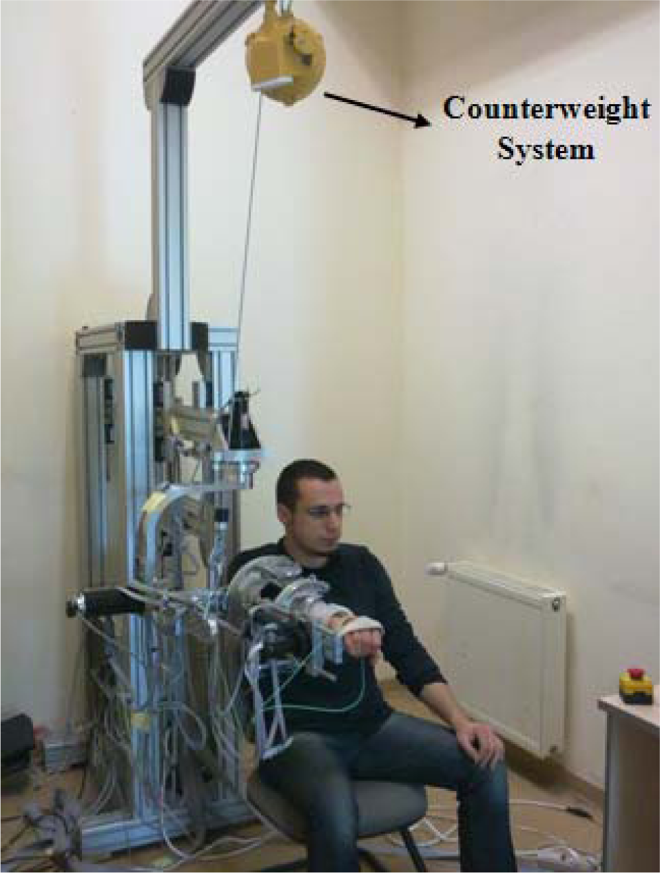
RehabRoby with Counterweight System
RehabRoby has been interfaced with Matlab Simulink/Realtime Workshop to allow for the fast and easy development of the system. The Humusoft Mf624 model data acquisition board (HUMUSOFT Inc., Czech Republic), which is compatible with Real Time Windows Target toolbox of MATLAB/Simulink, has been selected to provide real time communication between the computer and the electrical hardware. Digital incremental encoders are coupled with Maxon models of brushed DC motors for joint position measurement. Five of the six encoders have a resolution of 500 counts/turn, and one of them has a resolution of 1000 counts/turn. The encoder data of the motors is received through a Humusoft Mf624 with a 500Hz sampling rate. The force values measured from the force sensors are recorded using the Humusoft Mf624 data acquisition card with a sampling rate of 500Hz. A 19″ LCD screen is positioned in front of the subject at a distance of about 1m to demonstrate the movement activities to be performed.
2.3 Controllers
The low-level controller provides RehabRoby with the desired motions for the rehabilitation task.
RehabRoby has complex and uncertain inner dynamics, and it is sensitive to external forces during the human-robot interaction, thus a simple Proportional-Integral-Derivative (PID) or model-based position control technique may not be enough to complete the task in the desired manner. Thus, in this study, an admittance control with an inner robust position control loop is used as the low-level controller of RehabRoby (Figure 5).

Low-Level Controller of RehabRoby
The effects of the parametric uncertainties in the dynamic model and the additional external disturbances are compensated for with an equivalent disturbance estimator in the robust position controller. Various methods have been used to estimate the disturbance in the position control of robotic systems such as adaptive hierarchical fuzzy algorithms [17] or model-based disturbance attenuation [24]. In this study, we use a discrete Kalman filter-based disturbance estimator [25],[26]. To our knowledge, admittance control with an inner robust position control loop has not been used to control a robot-assisted rehabilitation system before.
The force that is applied by the subject, which is measured using a force sensor, is converted to torque using the robot Jacobian matrix. The torque value is then passed through an admittance filter [27], which is used to define the characteristics of the motion of RehabRoby against the applied forces, to generate the reference motion for the robust position controller. The reference motion is then tracked with the robust position controller, which consists of a linear Kalman filter-based disturbance estimator [26]. The admittance filter that maps the applied torque to the angular references for each joint is modelled by:

where τa, Md, Bd and Kd represent applied torque, desired inertia, viscosity and stiffness matrices, respectively. qr, q̇r ve q̈r are reference joint angle, angular velocity and angular acceleration respectively. Each joint equation is modelled individually. The coupling effects are included in the disturbance estimator. Eqn.1 can be represented in the frequency domain as:

The reference motion is generated by assigning the desired values to Md, Bd and Kd parameters in the admittance filter, and the robust position controller in the inner loop is responsible for tracking the reference motion (Figure 5).
The state feedback technique with two feedforward compensation terms is used in the robust position control. One of the feedforward terms is used to compensate for the modelled RehabRoby dynamics and the other term is used to eliminate the time-varying equivalent disturbances that come from the unmodelled RehabRoby dynamics and unknown external effects. The disturbances are estimated with a recursive algorithm, which uses the discrete linear Kalman filter (LKF) method. The dynamic equation of a robotic system in a joint space is:

where τ is the 6×1 joint torque vector, M(q) is the 6×6 manipulator inertia tensor, q, q̇ and q̈ are the 6×1 joint position, velocity and acceleration vectors, V(q, q̇), b(q̇) and G(q) are 6×1 Coriolis and centrifugal, friction and gravity force vectors, respectively. τext is the 6×1 torque vector that occurs due to unknown external effects. The inertia tensor M(q) is expressed as:
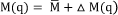
where the constant diagonal terms of the manipulator inertia tensor M(q) are represented as M̅ = diag(M̅1,M̅2,.…,M̅n) n=1,2…,6, and the other terms of M(q) are represented in Δ M(q). The friction term b(q̇) is expressed in the same way as in M(q).

where Bv is the 6×1 viscous-friction coefficient vector. An equivalent disturbance vector d′ (6×1), which includes Coriolis, centrifugal and gravity forces, parameter variations in inertia tensor and friction terms, and unknown external effects, is defined as:

By substituting Eqn.6 in Eqn.3, the dynamic model for the RehabRoby can be obtained as τ = M̅q̈ + Bvq̇ + d′. The relationship between the joint torque, and the current reference of the actuator is taken as τ = ktkgrir + Δ τ, where kt is the nominal value of the motor torque constant, kgr is the gear ratio of the actuator and ir is the current reference. Δ τ includes both variations of the motor torque constant with respect to its nominal value, kt, and the variations of the motor's current value with respect to the current reference value, ir. Thus, the total equivalent disturbance d is calculated as d = d′ – Δ τ. The acceleration q̈ is found using q̈ = (Ktrir – Bvq̇ – d)/M̅, where Ktr is a 6×6 diagonal matrix which is calculated by multiplying kt and kgr.
The pole placement with state feedback method is used for the position control of RehabRoby. The state space model for the ith joint of RehabRoby is:
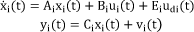
where ẋi(t) = [qi(t)q̇i(t)]T is the 2×1 state vector, ui(t) = iri(t) is the control input (motor current reference), udi(t) = di(t) is the equivalent disturbance, yi(t) = qi(t) measured output, and vi(t) is the measurement noise. The system matrix Ai (2×2 matrix), the control input matrix Bi (2×1), the disturbance matrix Ei (2×1) and the output matrix Ci (1×2) are given by:

The control input ui(t) is selected as ui(t) = − KiXi(t) + ri(t) where ri(t) = kpiqri(t) + idi(t) + ici(t). Ki is 1×2 state feedback gain matrix and Ki = [kpi kdi], where kpi and kdi are proportional and derivative gains, respectively. qri(t) is the reference position for the ith joint. idi(t) is the estimated value of the equivalent disturbance. idi(t) is calculated using idi(t) = d̂(t)/Ktri, where d̂(t) is the estimated value of the equivalent disturbance. ici(t) is the other feedforward compensating signal which is calculated using ici(t) = (M̅i/Ktri)q̈ri(t) + ((Bvi/Ktri) + kdi)q̇ri(t). Eqn.7 with state feedback becomes

The characteristic equation of the system defined in Eqn.9 is represented as
The equivalent disturbance d̂(t) is estimated using a recursive algorithm which is based on the linear Kalman filter design. The state space model given in Eqn.9 is extended by including the estimated equivalent disturbance as a new state variable. The extended model is still linear and time-invariant because the equivalent disturbance is independent from the state variables [28]. The linear Kalman filter algorithm used in the estimation of the equivalent disturbances is defined in discrete state space. The discrete state space model of the ith joint of RehabRoby is described as:
where

where Ts is the sampling time, which is selected to be smaller than T. The states at time (k) are predicted using the states estimated at time (k-1) in the discrete linear Kalman filter algorithm using
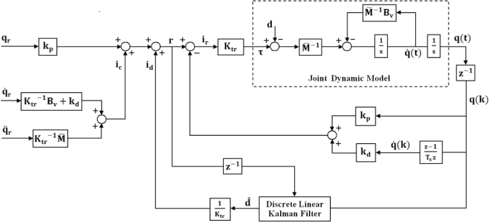
Robust Position Controller with Disturbance Estimator
The high-level controller implements the decision-making mechanism of RehabRoby. The high-level controller decides the necessary changes by analysing the information that comes from the sensor information module or from the therapist. It plays the role of a human supervisor (therapist) who would otherwise monitor the task and assess whether it needs to be updated. A hybrid system modelling technique is used to design the high-level controller because it is easy to add new rules related to the rehabilitation task using this technique (Figure 7). The states of the high-level controller are defined in advance. When the task execution starts, the starting and final positions (reference) of the joint angles (θ, joint angle vector) of RehabRoby are initialized in the initialization state. The passive state (mode=0) (passive mode), active state (mode=1) (active–assisted mode) or admittance control state (mode=2) (resistive mode) are activated based on the therapy mode that the therapist selects. In the passive mode, the rehabilitation task is performed only in the passive state, meaning that RehabRoby is only responsible for helping the subject complete the task when the subject is passive. The subject's motion is checked periodically in the active-assisted and resistive modes. If the subject's movement, which is measured as (θ) of RehabRoby, is out of limits (θ ≥ |ε|), then the position control state becomes active. When the position control state is active, then RehabRoby provides assistance to the subject in performing the motions until the subject's movement is in the desired motion range. When the subject's movement is in the range of the limits (θ < |ε|), then the state, which is active (active state or admittance control state) before entering the position control state, becomes active again. In any state, the safety conditions of RehabRoby, which are position, velocity and torque limits are checked periodically, and if any unsafe situation occurs (e=1), then the emergency stop state is activated and the execution of the task is stopped.

High-Level Controller of RehabRoby
2.4 Task Design
Two well-known rehabilitation tasks were selected in consultation with therapists at Yeditepe University's Physiotherapy and Rehabilitation Department. One of the rehabilitation tasks was the elbow flexion movement (i.e., reaching chest to do up buttons) (Task1) and the other was elbow flexion with a shoulder flexion movement (i.e., reaching mouth to eat) (Task2). Subjects were seated in the chair, and their arms were placed in the splint and tightly secured with Velcro straps (Figure 2-Middle). The height of the RehabRoby was adjusted for each subject so that they would start the task in the same arm configuration by changing L3 (Figure 3). Initially, the subject's shoulder was positioned at an extension of 90°, the elbow was it the neutral position, the lower arm was at a pronation of 90°, and the hand and the wrist were free it the neutral position (Figure 8a). In Task1, the subjects were asked to flex their elbows to 90° in 30 seconds (Figure 8b and Figure 8c). In Task2, the subjects were asked to flex their elbows to 90° and flex their shoulders to 20° in 30 seconds (Figure 8d and Figure 8e).

Task1 and Task2 (a) Initial Position of Both Taskl and Task2, (b) Middle Position of Task1, (c) Final Position of Task1, (d) Middle Position of Task2. (e) Final Position of Task2
It would have been possible for the subjects to perform the rehabilitation tasks in the three therapy modes. However, we only used the active-assisted mode therapy (AAMT) and the resistive mode therapy (RMT) in this study. In AAMT, RehabRoby was kept passive and the subjects were asked to perform the tasks by themselves, and RehabRoby provided assistance to the subjects when they could not follow the desired movement. No resistance was applied to the subject's movement in AAMT. In RMT, subjects were asked to perform the tasks with a comfortable resistance applied by RehabRoby using the admittance control with an inner robust position control loop and RehabRoby provided assistance to the subjects when they could not complete the desired movement. The resistance applied in the resistive mode was quite large compared with the resistance that is caused by the inherent dynamics of RehabRoby, thus the resistance of the system in RMT was neglected. The parameters in the admittance filter, which provided comfortable resistance, were determined experimentally. The parameters in the admittance filter were selected as Md = 4, Bd = 3 and Kd = 0 for Task1, and Md = 2, Bd = 120 and Kd = 0 for Task2.
2.5 Ethics Statement
This study was approved by the Institutional Review Board of Yeditepe University Hospital (IRB #032). The subjects were informed of the experiment protocol and an orientation was given on each subject.
2.6 Subjects
Nine subjects (four female and five male), whose ages were in the range of 22 to 26, participated in this study. None of them had any motor impairment in their arms. The right hand was dominant in seven of the subjects, and the left in two.
2.7 Data Analysis
The subjects completed three questionnaires (Perceived Rate of Exertion (PRE) [30], Visual Analogue Scale (VAS) [31] and a questionnaire for the assessment of the technical applicability of the RehabRoby) on the usability of the RehabRoby. PRE was applied to help understand the amount of exertion that the subjects felt during the task execution, and the VAS to assess the amount of difficulty experienced while using the RehabRoby. The last questionnaire was designed for the assessment of the technical applicability of the RehabRoby, and was prepared by an expert in human factors. The questionnaire consisted of ten questions, which evaluated the usability, comfort, performance and safety of the system on a five point Likert scale.
3. Experimental Results
3.1 Evaluation of the Performance of the Robust Position Controller
The performance of the robust position controller with and without the discrete linear Kalman filter-based disturbance estimator was evaluated. The values of the M̅ matrix (Eqn.4) were calculated experimentally and viscous friction coefficients were taken from the datasheets of the DC motors of RehabRoby. Ktr values were calculated by multiplying the torque constant by the gear ratio of the joint (Table 2). The damping ratio (
The Position Controller Parameters and RehabRoby Model Parameters


Robust Position Controller without Disturbance Estimator

Robust Position Controller with Disturbance Estimator
3.2 Evaluation of Performance of Subjects with RehabRoby
Subjects were asked to perform Task1 and Task2 in AAMT and in RMT. The subjects were required to move from 0° to 90° for Task1 and they were asked to track a ball (green ball in Figure 11). The actual position of the subject (blue ball), the desired position (green ball) and the desired motion (black line) (Figure 11) were shown live to the subjects using a computer screen. The upper and lower limits of the desired motion of Task1 were shown as perpendicular lines at an equal absolute distance from the desired position (green ball) (Figure 11-Teft). The circular area was used to demonstrate the limits of the desired motion for Task2 (Figure 11-Right).

Visual Feedback (Left:Task1, Right:Task2)
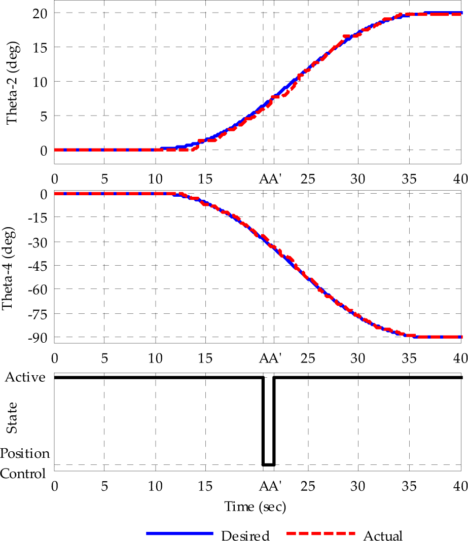
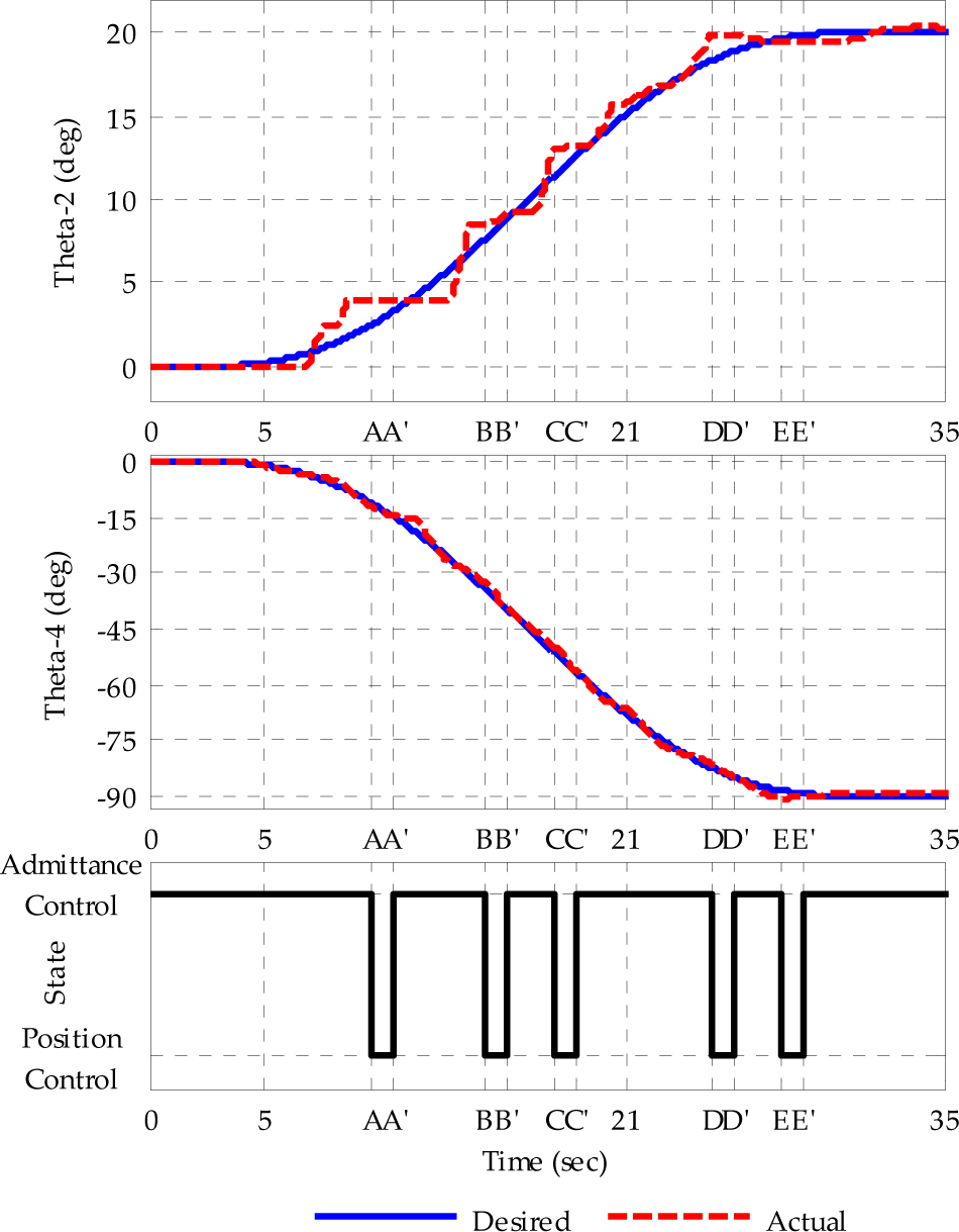
The subjects were asked to complete Task1 and Task2 using AAMT and RMT. The maximum deviation from the desired trajectories allowed was selected as 1.5°. It will be possible to increase/decrease the deviation angle depending on the patient's movement capabilities in the future. The subject's movement was checked every two seconds. If the subject's movement was out of the limits of the desired motion, then RehabRoby was activated in order to provide assistance to the subject in bringing his/her motion into the desired motion range using the robust position controller with the disturbance estimator. Experiments were performed with nine subjects; however, we have only presented one of the subjects' data here (S4). It can be seen that when the subject was not in the desired motion range, the admittance control with an inner robust position control loop became active at A (Figure 12) and the subject came back to the desired motion range at A′. When the subjects were in the desired range, then RehabRoby deactivated, and the subject continued to perform the task with his/her own exertion alone. It can be seen that the transition between the controllers when assistance was needed was smooth (Figure 12-b). This smoothness was achieved by applying proper filters to the reference trajectory signals at the moments of transitions. Smooth transitions between the controllers during rehabilitation therapies were important for completing the task in a safe manner. The subject needed assistance more number of times when he/she performed Task1 in RMT (Figure 13). The motion S4 in AAMT and RMT is given in Figure 14 and Figure 15, respectively. The subject needed assistance more number of times when he/she performed Task2 in RMT (Figure 15).

Motion of S4 ((a) Task1 in AAMT, (b) Smooth Transition between Controllers)

Motion of S4 during Task1 in RMT
Motion of S4 during Task2 in AAMT
Motion of S4 during Task2 in RAMT
The position errors were significantly larger in RMT than those in AAMT for both Task1 (p=0,008) and Task2 (p=0,008 for shoulder movement and p=0,011 for elbow movement). The maximum position error was observed during the shoulder movement of Task2 in the RMT mode (p<0,0001) (Table 3). The number of times that assistance was provided was greater when for both Task1 (p=0,031) and Task2 (p=0,006) in RMT. Most of the subjects needed assistance more number of times when they performed Task2 in RMT (p<0,0001) (Table 4).
Position Errors during Task1 and Task2 (AAMT; Active-assisted mode therapy, RMT; Resistive mode therapy, θ2 Angle of shoulder flexion/extension elevation, θ4 Angle of elbow flexion/extension axis)

The Number of Times Assistance during Task-1 and Task-2 (AAMT; Active-assisted mode therapy, RMT; Resistive mode therapy)

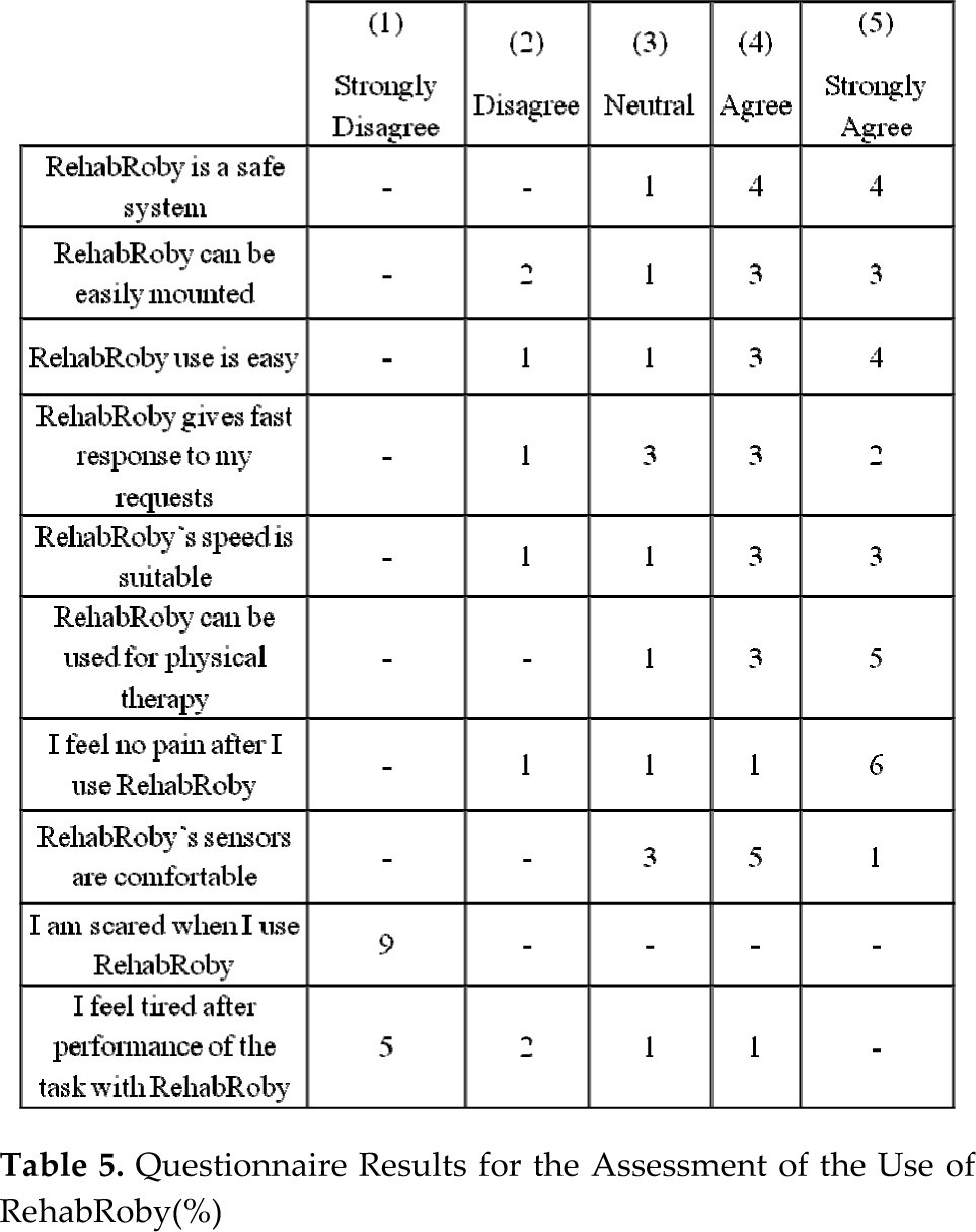
There was no significant relationship between the position errors and the VAS and PRE scores. The subjects' acceptance of RehabRoby was found to be 37.10±4.45 out of 50 points. The subjects stated that the task was difficult when there is no visual feedback. Based on the questionnaire, subjects agreed that RehabRoby is a safe system. Furthermore, the subjects thought that RehabRoby is easy to get on to and is easy to use (Table 5).
Questionnaire Results for the Assessment of the Use of RehabRoby(%)
4. Discussion and Conclusion
We have developed an exoskeleton type upper-extremity robot-assisted rehabilitation system called RehabRoby. RehabRoby is adaptable for male and female patients, can be adjusted for people with different arm lengths, and can be used by both the right and the left arm.
A control architecture which consists of a high-level controller and a low-level controller has been developed for RehabRoby. The high-level controller is the decision-making mechanism that decides the necessary changes in the low-level controller according to the sensory information or the therapist's commands. A hybrid system modelling technique has been used for the high-level controller, which provides flexibility in interfacing with the low-level controller without extensive redesign cost.
An admittance control with an inner robust position control loop, which provides RehabRoby with the motions to complete the rehabilitation task in the desired manner, is used. The level of resistance that is applied by RehabRoby can be varied using the admittance control based on the patient's movement capability. The admittance controller has been integrated with a robust position controller, which consists of a linear discrete Kalman filter to compensate for the effects of the parameter variations, and nonlinearities in the inherent dynamic model of RehabRoby, and the external forces that may occur during the human-robot interaction. When the disturbances are compensated for it then becomes possible to control the position of RehabRoby with feedforward and state feedback techniques using the robust position controller. We have shown that the tracking error decreased from 14° to 0.5° when the disturbance estimator was included in the robust position controller. Furthermore, the admittance control with an inner robust position control loop does not require an exact knowledge of RehabRoby's dynamic model, thus the computational effort of the control algorithm is minimized.
RehabRoby provides passive, active-assisted and resistive therapy modes. Thus, it is possible for low-functioning and high-functioning patients to use RehabRoby in their rehabilitation programs. In this study, two different rehabilitation tasks were performed using two different therapy modes (active-assisted and resistive) with healthy subjects to evaluate the RehabRoby system. The performance of the subjects when carrying out one dimensional and two dimensional tasks for both therapy modes were evaluated by calculating the position errors (the difference between the desired motion and the subject's motion). Additionally, the number of times that assistance was needed during the execution of both one dimensional and two dimensional rehabilitation tasks was recorded. The values of the position errors and the number of times that assistance is needed show that the subjects found the tasks more challenging in the resistive mode. It was also noticed that the admittance control with an inner robust position control provided assistance during the execution of rehabilitation tasks when subjects needed it. The transitions between the controllers (when needed) were completed in a smooth manner without causing any nonlinearities and jerks, which is an important issue during the execution of the rehabilitation tasks. Subjects thought that on the whole, the RehabRoby was safe, easy to use and easy to get on to.
The rehabilitation tasks that are performed by the subjects are designed in such a manner that they require cognitive processing. Including cognitive processing in the task design is an important criterion because it had been previously shown that movement tracking tasks that require cognitive processing achieved greater gains in stroke patients' brain reorganization than movement tasks that do not require cognitive processing[32]. In order to include cognitive processing within the rehabilitation tasks, we asked the subjects to follow a visually presented desired motion trajectory that is likely to command their concentration. It has been shown that therapy may be more successful if it informs patients of their progress toward their goals[33],[34]. Subjects are asked to pay attention to tracking the desired trajectory as accurately as possible, which keeps them focused on the task. The visual feedback is used not only to inform the subjects of how closely they are tracking the desired motion but also as a motivational factor to keep them focused on the task. Subjects found the task more difficult when performed with resistance without visual feedback.
The relatively small sample size can be considered a limitation of this study. More studies should be performed to comparatively evaluate the RehabRoby system for the rehabilitation of the upper extremities of stroke patients. Additionally, an adaptive Kalman filter which adjust the admittance parameters of RehabRoby for each subject can be integrated in the proposed robust position controller. Capability of RehabRoby can be extended by adding new therapy modes.
Footnotes
5. Acknowledgments
We gratefully acknowledge the help of Prof. Serap Inal and Prof. Sule Badilli Demirbas, who are in the Physiotherapy and Rehabilitation Department of the Faculty of Health Sciences Yeditepe University, for their valuable feedback concerning the task design. The study was supported by the Support Programme for Scientific and Technological Research Projects (TUBITAK-3501) under Grant 108E190.