
Abstract
An innovative lower extremity exoskeleton, SJTU-EX, is demonstrated in Shanghai JiaoTong University, which mainly aims to help soldiers and workers to support a payload in motion. This paper summarizes the mechanical design of SJTU-EX. Each pseudo-anthropomorphic leg of SJTU-EX has four active joints and two passive joints, and the joint ranges are optimized in consideration of both safety factors and the realization of typical motions. Springs are applied in the leg to eliminate the effect of gravity. The results of dynamic simulations are used to determine the actuated joints and the passive joints. Novel Hy-Mo actuators are introduced for SJTU-EX and the layout of the actuator for Diamond Side 2 is described in detail as a design example.
1. Introduction
Heavy objects are typically transported using wheeled vehicles. Many places in the world are too rugged or enclosed for vehicles to access, such as rocky terrains and stairs. Accordingly, legged locomotion becomes an attractive method of transportation, since legs can adapt to a wide range of extreme terrains. A lower extremity exoskeleton is thus proposed to assist with the most typical legged motion, ‘human walking’.
A lower extremity exoskeleton is a mobile machine worn by a person that supplies at least part of the activation-energy for limb movement. It combines human intelligence and machine power such that it enhances the intelligence of the machine and the power of the human operator. As a result, the human operator can achieve what he would not otherwise be capable of by himself [1].
SJTU-EX is a powered, lower extremity exoskeleton designed to assist and protect soldiers and construction workers. It comprises a rechargeable battery as the power supply, two pseudo-anthropomorphic legs and a backpack-like frame to mount varieties of loads. The parallel-series leg structure with four active joints and two passive joints can significantly improve load capacity. With the help of buffering springs on the legs, SJTU-EX can eliminate the effect of gravity during motion. Unlike most current exoskeletons with a fixed-length distance between the joints, SJTU-EX can automatically adapt to a wide range of human physical sizes when worn. It allows the wearer to accomplish typical motions of human lower limbs, like walking, jogging, squatting and stair climbing. It is our vision that SJTU-EX can be applied in rescue zones like nuclear plants. For example, SJTU-EX might help a rescue worker at Fukushima Nuclear Power Plant to support the weights of the lead coat and devices so that the worker can manipulate faulty equipment inside the plant. It is convenient to protect the exoskeleton from dangerous environments, like radiation because no devices or actuators are mounted along the legs.
2. Background
In recent years, research into lower extremity exoskeletons has become a hot topic. Several organizations all over the world have designed impressive exoskeletons for power augmentation, differing significantly in performance and the technology used. They can be broadly categorized into two groups: passive or quasi-passive exoskeletons and powered exoskeletons.
2.1 Passive and quasi-passive exoskeletons
A quasi-passive leg exoskeleton has been presented for load-carrying augmentation during walking by the Biomechatronics Group at the Massachusetts Institute of Technology Media Laboratory. The exoskeleton has no actuators - only ankle and hip springs and a knee variable damper. Without a payload, the exoskeleton weighs 11.7 kg and requires only 2 W of electrical power during loaded walking. For a payload of 36 kg, the quasi-passive exoskeleton transfers on average 80% of the load to the ground during the single support phase of walking. The exoskeleton slightly increases the walking metabolic cost of transport (COT) as compared to a standard loaded backpack (10% increase) [2].
Another energetically-autonomous powered knee exoskeleton developed in the MIT Lab facilitates running. The device consists of a knee brace in which a motorized mechanism actively places and removes a spring in parallel with the knee joint. This mechanism is controlled such that the spring is in parallel with the knee joint from approximately heel-strike to toe-off, and is removed from this state during the swing phase of running. In this way, the spring is intended to store energy at heel-strike which is then released when the heel leaves the ground, reducing the effort required by the quadriceps to exert this energy, thereby reducing the metabolic cost of running [3].
A gravity-balancing, lower extremity exoskeleton developed at the University of Delaware, Newark, is a simple mechanical device composed of rigid links, joints and springs. It is adjustable to the geometry and inertia of the leg of the human subject wearing it. This passive exoskeleton does not use any motors or controllers, yet can still unload the human leg joints of the gravity load over the full range of motion of the leg [4].
2.2 Powered exoskeletons
The ‘Berkeley Lower Extremity Exoskeleton’ (BLEEX) consists of two powered anthropomorphic legs, a power unit and a backpack-like frame on which a variety of loads can be mounted. BLEEX features three degrees of freedom at the hip, one at the knee and three at the ankle. Of these, four are actuated: hip flexion/extension, hip abduction/adduction, knee flexion/extension, and ankle flexion/extension. Of the unactuated joints, the ankle abduction/adduction and hip rotation joints are spring-loaded, and the ankle rotation joint is free-spinning [5]. The exoskeleton allows a person to comfortably squat, bend, swing from side to side, twist, walk and run on ascending and descending slopes, and step over and under obstructions while carrying equipment and supplies [6].
The Sarcos Research Corporation (Salt Lake City, UT) has worked toward a full-body ‘Wearable Energetically Autonomous Robot’ (WEAR) under the DARPA EHPA programme. The Sarcos exoskeleton has reportedly been successful in demonstrating a number of impressive feats: a structure supporting an entire load of 84 kg, a wearer standing on one leg while carrying another person on their back, walking at 1.6 m/s while carrying 68 kg on the back and 23 kg on the arms, walking through 23 cm of mud, as well as twisting, squatting and kneeling[7].
The exoskeleton robot suit, ‘Hybrid Assistive Limb’ (HAL) is proposed by the University of Tsukuba. It is composed of three main parts: a skeleton with an actuator, a controller and a sensor. The exoskeleton frame consists of a three-link, two-joint mechanism with the links corresponding to the hip, the thigh and the lower thigh, and the joints corresponding to the hip and the knee joints of the human body [8]. HAL uses electrical signals sent to the muscles from the brain to anticipate the wearer's movement. HAL's ability to anticipate movement allows it to move fractions of a second before the wearer, providing seamless interaction between human and robot [9].
The Honda Motor Company has been working on exoskeletons at its Fundamental Technology Research Centre in Wako, Saitama, and unveiled an experimental “walking assist” device in late-2008. It weighs 6.5 kg and its two electric motors are powered by a lithium-ion battery that lasts for about two hours between charges, so long as the wearer is not walking faster than 2.8 mph (4.5 km/h). Essentially a chair with legs, the Honda exoskeleton allows users to sit down in a saddle-like seat and strap their feet into two shoes attached to artificial limbs. The seat supports a portion of the wearer's body weight, reducing the strain to the joints in the knees, ankles and hips [10].
A one degree of freedom exoskeleton called ‘RoboKnee’ is presented by the Florida Institute for Human and Machine Cognition and Yobotics Inc. The user's intent is determined through the knee joint angle and ground reaction forces. Torque is applied across the knee in order to allow the user's quadriceps muscles to relax. RoboKnee allows the wearer to climb stairs and perform deep knee bends while carrying a significant load in a backpack. The device provides most of the energy required to work against gravity while the user stays in control, deciding when and where to walk, as well as providing balance and control [11].
Another IHMC ‘Mobility Assist Exoskeleton’ developed at the Florida Institute for Human and Machine Cognition is a robotic suit that a user can wear for strength augmentation or gait generation. The main goal is to successfully enable a person who cannot walk without assistance to do so in a straight line for a distance of 15 feet. When in disable assist mode, this prototype will rely on the user to provide balance control, and thus an external means for balancing will be required, such as crutches or a walker. Power and control is off-board and supplied to the exoskeleton by means of a tether [12].
From the above discussion of current exoskeletons, we can see that the principle behind a passive or quasi-passive exoskeleton is to store the energy at desired instances of the gait cycle and release it when more power is required. With the help of springs, the energy during a gait cycle is redistributed and thus the peak values of the human joints? power are smaller. However, it is not possible to help support heavy loads for passive or quasi-passive exoskeletons because there is no additional power input. As for powered exoskeletons, they are mainly designed to help humans carry payloads. As a result, the joints of exoskeleton with the highest power consumption during gait cycles are set to be actuated while the remaining joints are passive, usually with springs to make wearers comfortable. SJTU-EX is a pseudo-anthropomorphic exoskeleton with four actuated joints and two passive joints. Unlike other powered exoskeletons, the springs are mounted on both the active and passive joints of SJTU-EX. The springs on the active joints store the energy when the leg of the exoskeleton is in the swing phase of a gait cycle, and release the energy to help support the weight of the exoskeleton and the load when in the stance phase.
3. Mechanism design and optimization
3.1 Determination and distribution of degrees of freedom
Fundamental to designing a lower extremity exoskeleton is to determine the degrees of freedom of the exoskeleton leg. To better follow human motions and minimize kinematic constraints experienced by the wearer, the exoskeleton leg should have sufficient degrees of freedom as compared to a human's leg.
The human hip is a ball and socket joint with three degrees of freedom. The human knee joint is a complex combination of rolling and sliding between the femur and tibia, which allows the joint's centre of rotation to move as the knee flexes. The human knee also has three degrees of freedom but the joint rotation ranges are much smaller than the hip joint range [13]. According to the Clinical Gait Analysis (CGA) Data [14] of a walking gait cycle, the movement of the human lower limbs in the sagittal plane is the basic movement form. The hip and knee flexion/extension joints provide most of the torque to support the body weight, while the ankle flexion/extension joint supplies the most torque to push the body forward.
In consideration of mobility, it is best for an exoskeleton to inherit all seven degrees of freedom in a human leg. However, the degrees of freedom of ankle rotation are removed in SJTU-EX because its motion can be partly realized by hip rotation. The presence of six degrees of freedom instead of seven for SJTU-EX engenders to simplicity and robustness in addition to more straightforward dynamic modelling. On the other hand, the issue of how to lay out the two degrees of freedom of the hip and knee flexion/extension becomes critical for an exoskeleton specialized for load carrying. Traditional exoskeletons usually connect the hip joint and the knee joint in series as an anthropomorphic architecture, sacrificing load-supporting capability. As for SJTU-EX, a parallel diamond mechanism with two rotational degrees of freedom is introduced - as shown in Figure 1 - and it works in the role of the hip and knee flexion/extension joints. The two joint angles between the two diamond sides and the sagittal axis are denoted by θ1 and θ2, which are clockwise negative. θ1 and θ2 together determine the location of the ankle joint in the sagittal plane. The parallel diamond mechanism is prominent in the load supporting capability and can also provide a large workspace for the motion of human feet.

Distribution of the degrees of freedom
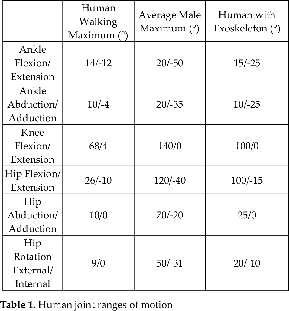
In summary, a pseudo-anthropomorphic architecture is chosen for SJTU-EX, which has ankle and hip joints similar to a human but no knee joints. Each SJTU-EX leg has four degrees of freedom at the hip and two degrees of freedom at the ankle. The hip abduction/adduction axis R1 and the two joint axes of the diamond mechanism R3 and R4 all pass through the human hip joint O. The hip rotation axis R2 is placed behind the wearer and thus it no longer passes through the human's hip joint. Such a design helps prevent the exoskeleton from interfering with the wearer and avoids the singularities of some human hip postures. Some unexpected behaviour on the part of the exoskeleton does occur in practice since the hip rotation axes of the exoskeleton and the wearer are not the same. However, the result is not serious because the motion range of the hip rotation joint is small during walking, as shown in Table 1. Additionally the distance between the axis R2 and the vertical axis is kept small in order to prevent any such unexpected behaviour.
Human joint ranges of motion
The SJTU-EX ankle has a flexion/extension axis R5 and an abduction/adduction axis R6. Both ankle axes are designed to pass through the human's ankle joint A.
3.2 Determination and optimization of the joint range
SJTU-EX is designed to be worn by humans of a height between 1.60 m and 1.80 m. Thanks to the diamond mechanism, the exoskeleton can automatically adapt to the height of the wearer when worn. For example, when a tall person puts on SJTU-EX, the diamond angle α becomes small and hence the whole exoskeleton is lengthened. A smaller diamond angle α contributes to the better load-supporting capability of the exoskeleton. So, less torque and power are needed when worn by a tall person. The smallest diamond angle α is set to be 10° when a 1.80 m tall person wears the exoskeleton and stands straight. The length of the Diamond Side L can then be determined by Eq. (1):

where hH-A is the distance between the hip and the ankle and is approximately equal to 51.3% of the height of a person [15].
The joint ranges of SJTU-EX should be large enough to allow the wearers to accomplish typical motions of the lower limbs. On the other side, the SJTU-EX joints should also limit the mobility of the wearer to some extent so as to prevent them from moving beyond the maximum ranges of the human joints. Otherwise, it may cause damage to the wearer. As such, it is important to investigate the motion abilities of the human joints.
Walking is the most fundamental human motion and must be realized by the SJTU-EX wearer without any difficulty. The data in column one [14] of Table 1 indicates the ranges of the human joints during a walking cycle. The maximum ranges of the human joints are shown in column two [15] of Table 1. The ranges of the human joints with SJTU-EX (shown in column three of Table 1) should be larger than the data in column one and smaller than the data in column two.
SJTU-EX's legs are similar to human lower limbs in their kinematics, except for the hip and knee flexion/extension joints. Accordingly, the joint ranges of SJTU-EX shown in Table 2 are set to be equal to the data in column three of Table 1 for the hip abduction/adduction joint, the hip rotation joint and the two ankle joints. The joint angles θ1 and θ2 between the two diamond sides and the sagittal axis are determined by the ranges of the hip and knee flexion/extension joints in column three of Table 1.
Joint ranges of SJTU-EX

The workspace of the ankle relative to the hip in the sagittal plane is shown as the shaded area A0°A‘0°A’100°A100° in Figure 2. It is determined by the hip flexion/extension joint angle θhip ranging from −15° to 100° and the knee flexion/extension joint angle θknee ranging from 0° to 100°. Arc A0° A‘0° is centred at hip joint O with a radius of OA0°. Arc A’0°A‘100° is centred at knee joint K’−15° with a radius of K‘−15°A’0°. Arc A‘100°A100° is centred at hip joint O with a radius of OA100°. Finally, arc A100°A0° is centred at knee joint K100° with a radius of K100°A0°. However, a realistic workspace requires that the motions of the two joints are dependent on each other, especially near the boundary of the workspace. For example, Posture A (θh = −15°,θk = 100°) and Posture C (θh = 100°,θk = 0°) are not able to be accomplished by most people, and thus should be removed from the workspace.
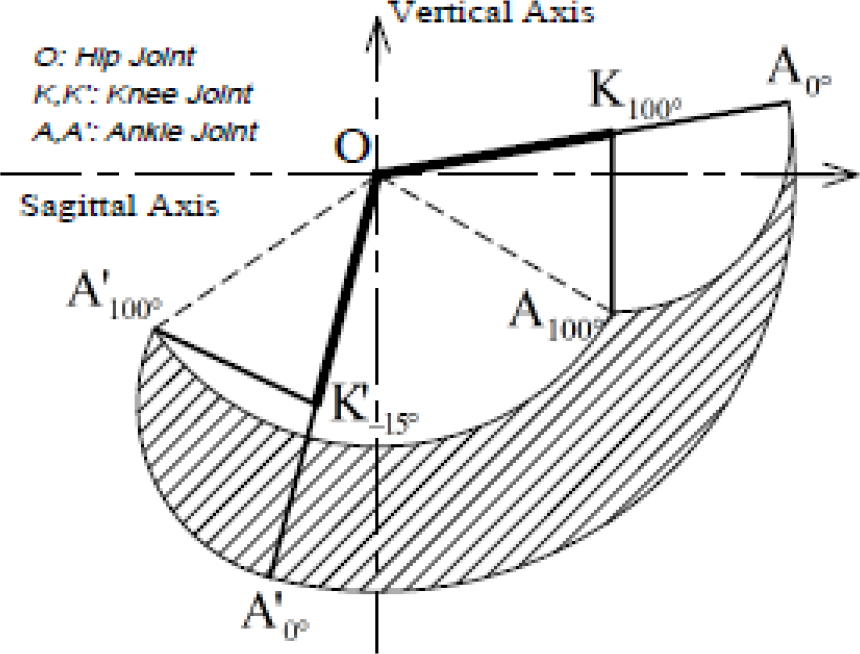
Workspace of the human ankle
The workspace of the ankle relative to the hip is optimized by investigating the joint ranges of four typical human motions: walking, jogging, squatting and stair climbing, as shown in Figure 3. Two limit postures for θ1 and θ2 are then determined in Figure 4, which allow the wearer to accomplish the four typical motions. θ1min and θ2min can be found in Limit Posture 1 when θhip is equal to −10° and θknee is equal to 45°. θ1max and θ2max can be found in Limit Posture 2 when θhip is equal to 50° and θknee is equal to 0°.

Typical human motions

Limit leg postures with SJTU-EX
Since SJTU-EX is designed for users with a height between 1.60 m and 1.80 m, and the determination of the ranges of θ1 and θ2 should also take into account the wearer's height. For a given posture with the same θhip and θknee, a taller wearer will result in a smaller θ1 and a larger θ2 of the exoskeleton. θ1min is determined by Eq. (2) when SJTU-EX is in Limit Position 1 and worn by a 1.80 m person:

where L is the length of the diamond side and is equal to 0.232 m; hH-A is the distance between the hip and the ankle and is approximately equal to 0.854 m for a 1.80 m person.
θ1max is determined by Eq. (3) when SJTU-EX is in Limit Position 2 and worn by a 1.60 m person:

where L is the length of the diamond side and is equal to 0.232 m; hH-A is the distance between the hip and the ankle and is approximately equal to 0.820 m for a 1.60 m person.
So, the range of the joint angle θ1 is (–96°,–12°). In the same way, the range of the joint angle θ2 can be found to be θ2 ∊ (–154°,–45°). θ1 and θ2 are dependent upon one another and should also satisfy (4):

where 10° is the minimum diamond angle α when SJTU-EX is worn by a 1.80 m person and θknee is equal to 0°; 110° is the maximum diamond angle α when SJTU-EX is worn by a 1.60 m person and θknee is equal to 100°. Accordingly, the ranges of θ1 and θ2 are within a hexagon, as shown in Figure 5. θ1 and θ2 together determine the workspace of the ankle relative to the hip, and the optimized workspace with SJTU-EX is shown as the shaded area BCDEF in Figure 6. C and F are the end points of the diamond mechanism at the two limit postures, as shown in Figure 4. Curve CD is determined by increasing the angle of Diamond Side 1 θ1 while keeping Diamond Side 2 in Limit Posture 1 until the end point intersects with Arc A‘100°A100°. In a similar way, Curve FE is determined by decreasing the angle of Diamond Side 2 θ2 while keeping Diamond Side 1 in Limit Posture 2 until the end point intersects with Arc A’100°A100°. Arc BC is centred at knee joint K when θhip is equal to −10°. The optimized workspace BCDEF is inside the workspace A0°A‘0°A’100°A100° without SJTU-EX and encompasses the blue region, which indicates the ankle workspace for walking [16]. As such, both safety and the good motion ability of SJTU-EX can be guaranteed.
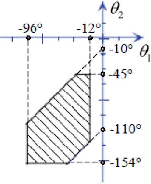
Ranges of θ1 and θ2

Optimized workspace of the ankle with SJTU-EX
3.3 Determination of actuated joints and passive joints
Each SJTU-EX leg has six degrees of freedom so as to follow the motion of the lower limbs well. However, actuating all of them would lead to high power consumption and control complexity. Instead, only those joints that require substantial torque and power during motion should be actuated. Walking is considered to be the principal human motion for exoskeletons and the corresponding joint torques and powers of SJTU-EX are set as the primary criteria to determine which joints to actuate.
A dynamic model of SJTU-EX is built to investigate the torques and the powers of the joints by the Lagrange equations of the second kind. The kinematic data for the two joints of the diamond mechanism are obtained from the motion data of human walking [17] by inverse kinematics so that the end point of the diamond mechanism can follow the motion of the human ankle. The kinematics of the other SJTU-EX joints is very similar to the kinematics of human joints, and thus can directly refer to the motion data of human walking. SJTU-EX is supposed to carry a payload of 70 kg, including its own weight. The vertical ground reaction force (GFR) of SJTU-EX during a gait cycle has two peaks, with the peak value about 120% of the total weight [18] shown in Figure 7. The leg of SJTU-EX is in swing phase during the first 40% of the cycle and in stance phase during the remaining 60% of the cycle.

GFR with a payload of 70 kg
The dynamic simulations are performed on the condition that SJTU-EX is worn by a 1.80 m person at a walking speed of 1.3 m/s. The torque and power results of each joint during walking are shown in Figures 8 and 9, respectively. The two joints of the diamond mechanism and the ankle flexion/extension joint all require a peak torque of more than 100 N · m and a peak power greater than 150 W. During a walking cycle, the diamond mechanism contributes mainly to supporting the whole body weight, while the ankle flexion/extension joint is responsible for pushing the exoskeleton forward. As the three joints with the highest power consumption, the two joints of the diamond mechanism and the ankle flexion/extension joint all need to be actuated.

Joint torques of SJTU-EX for walking with a payload of 70 kg

Joint powers of SJTU-EX for walking with a payload of 70 kg
The hip abduction-adduction joint of the exoskeleton requires a relatively small torque and low power during walking. However, it provides the lateral balancing forces and does become a high power consuming joint when walking sideways by abducting the leg to avoid obstacles. Consequently, it is also set to be actuated. Both the hip rotation joint and the ankle abduction-adduction joint require a small torque of less than 10 N · m and low power of less than 10 W. They are mainly designed to help accomplish the wearer's motions within these two degrees of freedom.
In summary, each SJTU-EX leg has four powered degrees of freedom: the two joints of the diamond mechanism, the ankle flexion/extension joint and the hip abduction-adduction joint. The hip rotation joint and the ankle abduction-adduction joint of SJTU-EX are left passive because they require only low power consumption. The necessary torques and powers of these two unactuated joints are provided by the wearer. As such, springs are applied to reduce the load on the human muscles and increase comfort.
3.4 Implementation of the springs in the diamond mechanism
The required torques and power for the actuated joints for SJTU-EX are calculated in Section 3.3 and are the primary criteria to select the appropriate actuators. However, more torque will be needed for the two joints of the diamond mechanism during walking if SJTU-EX is worn by a person who is shorter than 1.80 m. To compensate for the worsened load-supporting capability of SJTU-EX when worn by shorter persons, extension springs are applied in the shorter diagonal of the diamond mechanism, as shown in Figure 10.
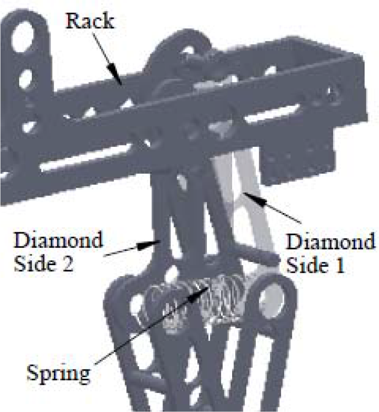
The diamond mechanism with a spring in the diagonal
The primary principle of the spring design is to shift a suitable amount of the torque from the stance phase to the wing phase so that the required peak torques for the two joints of the diamond mechanism are smaller. The selection of an appropriate spring should keep to the following three rules:
The spring is in the extension state when the wearer stands straight such that it helps the exoskeleton to support the load. A larger initial spring tension will lead to smaller driving torques for the diamond mechanism in the stance phase, while on the other hand it causes larger torques in the swing phase that are originally close to 0. An appropriate spring tension should result in almost the same peak torques for the swing phase and the stance phase during a walking cycle, as shown in Figure 11.
The spring stiffness k should be small so that it does not cause a big torque undulation in the swing phase. As a result, the initial spring elongation Δli must be large so as to provide the tension for Rule 1 according to Hooke's law F = k×Δl. The influence of various spring stiffnesses on the joint torque of Diamond Side 1 is shown in Figure 12.
The spring stiffness k in Rule 2 must guarantee the spring elongation Δl within the spring elongation limit during the motion cycle.

The influence of the spring tensions on the joint torque of Diamond Side 1

The influence of the spring stiffnesses on the joint torque of Diamond Side 1
Based on these three rules, springs with different stiffnesses k and initial lengths l0 should be chosen for various applications, according to the height of the wearer, the payload and the motion type.
Table 3 lists the simulation results for different wearers of heights ranging between 1.60 m and 1.80 m during walking. The implementation of the springs has an impressive effect on the reduction of the peak torques. The specifications of the springs in Table 3 can be referred to in practical use. The stiffness k in Table 3 means the total effective stiffness for the diamond mechanism. So, it should be half of the stiffness listed in Table 3 for each spring if two springs are mounted in the diagonals of the two diamonds, respectively. Springs are not necessary when the exoskeleton is worn by a 1.80 m person because the diamond mechanism keeps a small diamond angle α of less than 45° during walking. However, auxiliary springs should be mounted in the diamond mechanism to help accomplish other human motions, like squatting and stair climbing, when α becomes large and the load-supporting capability gets worse. The auxiliary spring will undertake increasing vertical load as the wearer squats and therefore obviously reduce the required torques for the two joints of the diamond mechanism, as shown in Figure 13.
Joint torques for walking with a payload of 70 kg


Joint torques for squatting and standing up with a payload of 70 kg
4. Actuation design
4.1 Hy-Mo
A novel ‘Hy-Mo’ actuator is applied in SJTU-EX to provide the required torque for each powered joint. The testing platform shown in Figure 14 consists of an accumulator, an oil tank, a pump, a motor driver, a DC motor and a Hy-Mo actuator. The working principle of Hy-Mo is to adopt motors instead of servo valves in order to realize the uncoupled force-position control and use hydro-cylinders to provide force. Compared to traditional hydraulic systems, the requirement for the hydraulic oil properties of the Hy-Mo system is lower due to the strong anti-pollution ability and the high system stability. The cylinder leak is only 10% of a traditional servo valve system and no conventional hydraulic devices - like filters and coolers - are required, which lowers the cost. The integrated design of the oil tank and the various mechanisms as shown in Figure 15 lightens the weight of the whole system.

The testing platform of Hy-Mo

Integrated design of the Hy-Mo system
4.2 Selection and layout of actuators
Hy-Mo actuators are only available in discrete sizes, as shown in Table 4. Since actuators of large sizes are always heavy and occupy large mounting spaces, the selection of the appropriate actuators generally begins with actuators of smaller sizes. The layout of the actuators is a trial and error process to find qualified locations for the actuator's endpoints on two neighbouring links. This process is iterated with actuators of different sizes and with different mounting points until the following three requirements are met: (1) the ranges of motion for each actuated joint described in Section 2.2 must be guaranteed within the actuator's stroke; (2) the generated torque must be larger than the required joint torque listed in Table 3; (3) the actuator line of action must not pass through the joint and no interference should take place between the actuators and the links [19].
Specifications of the Hy-Mo actuators

The actuator selection and layout for the joint of Diamond Side 2 is illustrated in Figure 16 as an example. Figure 16 shows the rotational plane of Diamond Side 2 around Hip Pivot O. OA and OC are the two limit positions for Diamond Side 2 according to the joint range θ2 ∊ (–154°,–45°) in Section 2.2. A and C are the force acting points of the actuator on Diamond Side 2, with a supposed distance of R from Hip Pivot O. According to the results of dynamic simulations, it is at θ2⊥ = −132° that a maximum torque of 127 Nm occurs for the joint of Diamond Side 2. Accordingly, the force acting line of the actuator l is designed to be perpendicular to Diamond Side 2 at θ2⊥ = −132° and the largest effective moment arm OB can be obtained. Actuator Pivot P is located along the force acting line l above Point A to prevent the actuator line of action from passing through Hip Pivot O during the whole motion. The required actuator stroke S is then calculated by Eq. (5):


Actuator layout for the joint of Diamond Side 2
S can be very close to the length of AC because Pivot P is usually placed far away from AC, according to the actuator size. As a result, the required stroke S will be approximately proportional to the largest effective moment arm R.
A qualified actuator should not only provide enough torque for the joint but also have a long stroke to accomplish the angular joint motion. Finally, a Hy-Mo actuator with a stroke of 50 mm is chosen to drive the joint of Diamond Side 2. The maximum effective moment arm R can be determined as 45 mm in Figure 17, with a corresponding stroke of less than 50 mm. The torques generated by the pull and push forces of the actuator are shown as the torque limits in Figure 18, which must exceed the required joint torque of Diamond Side 2 over the entire range of walking.
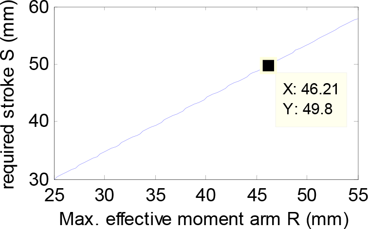
Relation between the stroke S and the moment arm R

Torque vs. angle for the joint of Diamond 2
The same actuator is chosen for the other three powered joints of SJTU-EX in a similar way. In consideration of safety and space-saving, the actuator for the joint of Diamond 1 is mounted at the same side of the diamond mechanism with the actuator for the joint of Diamond 2, as shown in Figure 19. Since the joint range of Diamond Side 1 is (–96°,–12°), an extended diamond side is needed for a longer moment arm and for avoiding the singular position. The actuator for hip abduction is placed inside the rack of the exoskeleton and behind the wearer. The ankle actuator is mounted behind the ankle joint to provide a larger pull torque for the ankle extension.

Layout of the hip actuators
5. Conclusion
In the paper, a pseudo-anthropomorphic exoskeleton SJTU-EX with six degrees of freedom is presented. Four joints with large power consumption are actuated according to the dynamic simulations. A parallel diamond mechanism with two degrees of freedom is introduced in place of the hip and knee flexion/extension joints for a better load-supporting capability. Springs are mounted on both the active and passive joints of SJTU-EX, which can eliminate the effect of gravity as well as increase comfort. Human joint ranges when wearing SJTU-EX are first determined and then the corresponding exoskeleton joint ranges are optimized on the basis of typical human motions. A novel actuator called ‘Hy-Mo’ is introduced to SJTU-EX, which utilizes hydraulics to provide power and adopts the motor to achieve position control. The actuator sizes and the actuator mounting points are selected according to the joint ranges and the required joint torques.
Future work will include the implementation of a six-axis force sensor on the exoskeleton foot to detect the human's intention as to motion and inclinometers on the human joints to measure the link angle relative to gravity. A force-displacement mixed control system will also be considered to enable the exoskeleton to follow the desired joint trajectories induced by the wearer's motions.
Footnotes
6. Acknowledgments
This work was partially supported by the National Basic Research Program of China (973 programme, grant no. 2013CB035501).