
Abstract
A wheel-legged hybrid robot was put forward. First, the mechanical design of this chassis was introduced. Second, based on the kinematic analysis, comparison between the robot with the active transition system and that with the passive transition system was made. Third, the process of overcoming three kinds of obstacles was simulated. Finally, the conclusion can be made that this hybrid locomotion mechanism with the active transition system has good performance on rough terrains.
Introduction
Generally, mobile robots can be classified into three types, including wheeled, tracked, and legged robots. 1 Wheeled robots have rapid motion speed and good stability on flat terrains, 2 but they have difficulty in overcoming obstacles on rough terrains. Tracked robots have better obstacle-negotiation ability and ground-adaptability on unstructured ground with the disadvantage of high energy consumption. Legged robots possess the best mobility performance on rough terrains with the disadvantages of low speed and complicated mechanism and control systems. Recently, wheel-legged hybrid mobile robots have become the research focus because many advantages of both wheeled and legged robots can be integrated.3,4
The locomotion mechanism of WorkPartner is composed of four legs and four wheels, mounted at the end of each leg, and has three locomotion modes: wheeled, legged, and wheel-legged. 5 Chariot has four legs and two wheels, each leg having 3 degrees of freedom.6,7 Roller-walker with four wheels and four legs has two locomotion modes, skating and walking. 8 However, the above-mentioned wheel-legged hybrid robots have separate legs and wheels, thus the mechanical and control systems are comparatively complicated. Epi.q, composed of four three-legged wheels, can move on flat terrains with wheels and overcome obstacles with legs. Locomotion mode is passively switched between wheeled and legged so that some unexpected locomotion transition will happen.9–11
In this article, a wheel-legged hybrid locomotion mechanism with an active transition system, called “TH-Wheg,” was designed and has two kinds of locomotion modes: wheeled and legged. Mechanical design was introduced in section “TH-Wheg.” Kinematics of this robot was analyzed, and comparison between the active and passive transition system was made in section “Kinematic analysis.” Dynamic simulation was made in section “Dynamic simulation.” Finally, some conclusions were drawn in section “Conclusion.”
TH-Wheg
Mechanical design
Overall mechanical design
The locomotion mechanism of TH-Wheg can be divided into four symmetrical locomotion units, composed of one three-legged frame and three small wheels. The three small wheels are, respectively, mounted on the end of three legs of the three-legged frame and are driven by the motors with the gear transmission system. The three-legged frame is actuated by the gear transmission reduction system and the clutch. Generally, wheeled locomotion is used on even ground with the advantages of fast speed and efficient energy consumption. When the robot encounters an obstacle, legged locomotion is adopted to surmount the obstacle (Figure 1). The key parameters of this locomotion mechanism are shown in Table 1.

Locomotion mechanism.
Key parameters of locomotion mechanism.

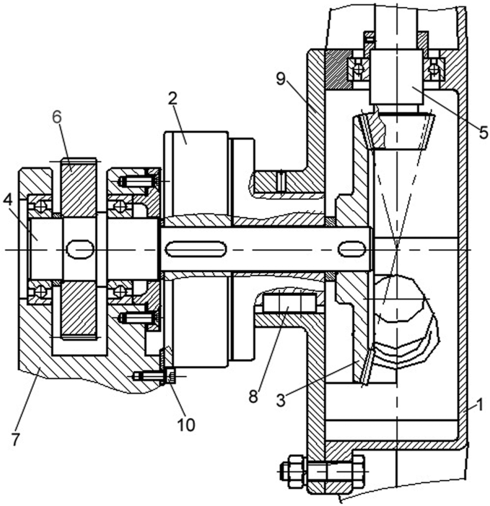
Mechanism of inner and outer shafts
We aim to develop a practical locomotion system with high cost effectiveness by reducing the number of motors. 5 Both the clutch and the mechanism of inner and outer shafts were adopted to actuate wheeled and legged motion by one motor.
As shown in Figure 2, the inner or outer shaft is, respectively, driven by turning on or off the clutch. When the clutch 2 is working and can be regarded as the outer shaft, TH-Wheg moves with the three-legged frame. In order to improve obstacle-negotiation ability, the motion and torque of the motor can be transmitted to the three-legged frame 1 by the gear transmission reduction system. When the clutch 2 is disconnected, TH-Wheg moves with the small wheels. The small wheels will be actuated by the motor with the transmission system, comprising the inner shaft 4 and two sets of bevel gears.
Mechanism of the inner and outer shaft.
Transmission system of three small wheels
In order to employ as few mechanical parts as possible, as shown in Figure 3, one bevel gear 2 is used to actuate three gear shafts 1. Figure 2 shows that the main transmission axis 4 is driven by the gear transmission system with high reduction ratio so as to enhance the output torque to surmount higher obstacles. On the other hand, the small wheels should have high speed on flat terrain, but the speed of the main transmission axis is relatively low. Two sets of bevel gears are employed to accelerate the motion speed of the small wheels on even ground.

Multi-wheel transmission mechanism.
Control system
The control system configuration is shown in Figure 4, including one Arduino board, one motor controller, and the ultrasonic sensors. The common sensors to detect obstacles are stereo cameras or ranger finders. In order to reduce the computational burden, the ultrasonic sensors would be installed to detect steps and ditches. Steps can be detected by the forward-looking ultrasonic sensors, and ditches can be sensed by the downward-looking ones. In this simulation, the terrain is given in advance.

Control system.
Kinematic analysis
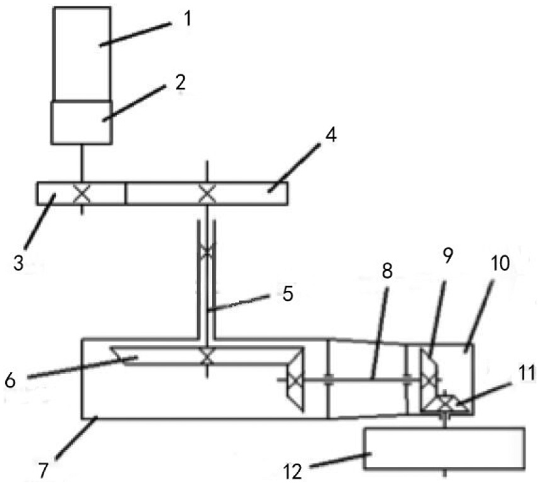
This locomotion mechanism was designed to move on flat ground with wheels and overcome obstacles with legs. The transition between wheeled locomotion and legged locomotion can be classified into two types: active and passive. In Figure 5, the active transition is triggered by the clutch. If the clutch is cut down, the passive transition can be easily obtained, as seen in Figure 6, and is automatically triggered by friction torque between the bottom wheels and ground.

Active transition schematic diagram.
Passive transition schematic diagram.
Active transition
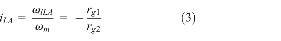
Wheeled locomotion analysis
When the robot moves on flat terrain, the clutch is disconnected. The main transmission axis is driven by the motor with one set of gear, and then three wheels are actuated by the main transmission axis with two sets of bevel gears. All the variables are explained in Table 2.
Nomenclature in (1)–(6).

In the wheeled motion mode, due to disconnection of the clutch, the three-legged frame has no angular velocity; therefore
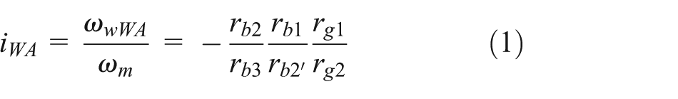

Legged locomotion analysis
In the legged motion mode, the clutch takes effect; thus the three-legged frame will be actuated by the clutch. Moreover, the gear shaft is embedded in the three-legged frame and rotates together with the three-legged frame, thus the bevel gear 1 keeps relatively stationary with the gear shaft. Consequently, the small wheel will be immobilized when the robot gets over obstacles by legs, so that the robot with the active transition can overcome not only steps but also cross ditch.
In the legged motion mode, the gear ratio


From equations (2) and (4), we can get equation (5). Due to

If the friction between the gears is omitted, we can get equation (6). Some conclusion can be drawn that the torque exerted on the frame in the legged motion mode is much bigger than that exerted on the wheel in the wheeled motion mode, which will be beneficial for obstacle negotiation.
Passive transition
If the clutch is removed from the locomotion system in Figure 4, the passive transition system will be obtained, as shown in Figure 5. When the robot runs into obstacles and the friction between wheels and ground is so great as to prevent the wheels from rotating, the legged locomotion is automatically triggered.
Supposed an observer placed on the three-legged frame, the transmission system can be regarded as an ordinary gearing. Consequently, the gear ratio of the transmission system is expressed as follows

In the wheeled motion mode, the gear ratio in the passive transition system is the same as one in the active transition system, and the three-legged frame keeps stationary:


In the legged motion mode, the small wheel is blocked by obstacles, and the three-legged frame begins to rotate with the small wheel. The gear ratio of the transmission system


During the mechanical design, inequation (16) should be assured to make the legged motion direction the same with the wheeled in the passive transition system

From equations (3) and (13), we can get equation (16)
Due to
Furthermore, the robot with the passive transition system cannot cross ditches because the small wheel has no chance to be stopped. However, the robot with the active transition system can get over steps, obstacles, and ditches.
Dynamic simulation
In order to test the obstacle-negotiation ability of the robot with the active transition system, automated dynamic analysis of mechanical systems (ADAMS) was adopted to make dynamic simulation. The simulations by the wheeled and legged motion were made to assess the obstacle-overcoming performance of different motion modes. As for legged motion, different kinds of obstacles were adopted to evaluate the detailed obstacle-overcoming ability.
A digital model in Solid Edge environment has been built and was imported into ADAMS by Parasolid format. The simulation condition is shown in Table 3.
Simulation parameter.

Different joints and constraints were introduced to TH-Wheg according to the different motion modes. In the wheeled motion mode, one revolute joint was applied between the three-legged frame and the chassis, also another revolute joint was exerted between the three-legged frame and the small wheel. Rotational motion was applied to the three-legged-frame-to-small-wheel joint. The contact force was added between the small wheel and the ground. In the legged motion mode, the difference is that the fixed joint was exerted between the three-legged frame and the small wheel and rotational motion was applied to the-three-legged frame-to-chassis joint. The snapshots, velocity, and acceleration curves of the obstacle-overcoming simulation were used to analyze the performance.
Obstacle overcoming by wheeled motion
The small step with the height of 60 mm was used to test the performance to overcome small obstacles by the small wheels. The small wheel with high speed of 688°/s is adopted to get over small steps (Figure 7). As shown in Figure 8, the velocity of the robot will considerably fluctuate during overcoming obstacles by the small wheels, especially when the front wheels cross the obstacle.

Simulation of small obstacle negotiation: (a) before obstacle-overcoming, (b) obstacle-overcoming of the front wheels, and (c) obstacle-overcoming of the rear wheels.

Velocity and acceleration curves during 60-mm obstacle overcoming.
As shown in Figure 9, the obstacle height is 40 mm. From Figures 8 and 9, we can conclude that the bigger the height of obstacle overcome by the small wheel, the more the robot speed fluctuates.

Velocity and acceleration curves during 40-mm obstacle overcoming.
Obstacle overcoming by legged motion
Maximum obstacle-negotiation height
The legged locomotion will be triggered when higher obstacles are run into. Figure 10 shows the simulation of obstacle negotiation with the theoretically maximum height of 750 mm.

Simulation of 750-mm obstacle overcoming: (a) before obstacle-overcoming, (b) obstacle-overcoming of the front wheels, (c) finishing obstacle-overcoming of the front wheels, and (d) finishing obstacle-overcoming of TH-Wheg.
The conclusion can be drawn that the maximum obstacle-negotiation height is 750 mm—60% of the locomotion mechanism height. As shown in Figures 11 and 12, the fluctuation of velocity during obstacle negotiation by the legged motion is comparatively lower than by the wheeled motion.

Velocity curve during 750-mm obstacle negotiation.

Acceleration curve during 750-mm obstacle negotiation.
Maximum ditch-crossing width
The ditch-crossing ability is very important for robots moving on natural terrain such as a path in a forest. 12 Figure 13 is the simulation of ditch crossing with the theoretically maximum width of 866 mm.

Simulation of ditch crossing: (a) before obstacle-overcoming, (b) obstacle-overcoming of the front wheels, (c) finishing obstacle-overcoming of the front wheels, and (d) finishing obstacle-overcoming of the rear wheels.
As shown in Figure 14, the biggest acceleration fluctuation occurred during ditch crossing for the front legged locomotion unit. The reason was that the rear wheel in the front locomotion unit slipped along the ditch.
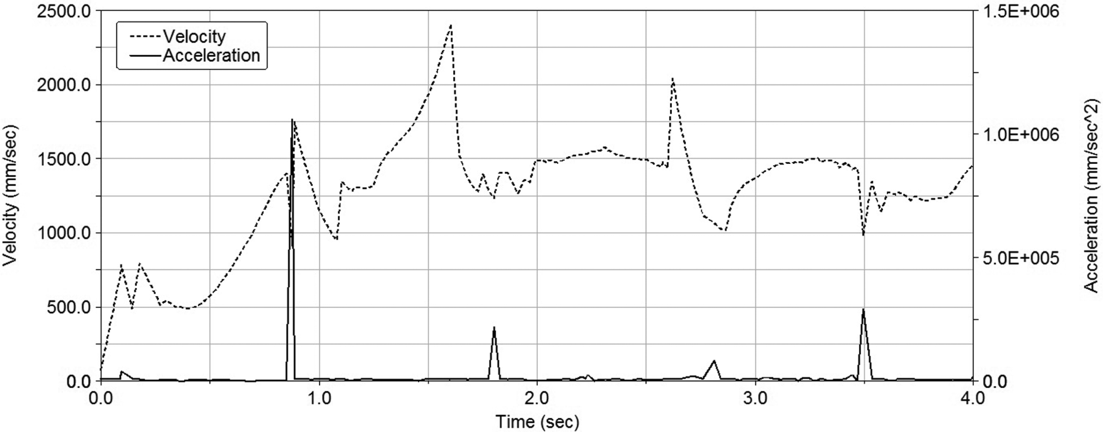
Velocity and acceleration curves during ditch crossing.
Figure 15 is the velocity and acceleration curves after changing the initial position of ditch crossing. As shown in Figure 15, the highest acceleration amplitude is 3.7 × 105 mm/s2—37% of the one in Figure 14.

Velocity and acceleration curves with the different initial positions during ditch crossing.
Combined obstacle overcoming
Figure 16 is the snapshots of the combined obstacle-overcoming simulation. As shown in Figure 16, TH-Wheg can continually get over three different kinds of obstacles. We can conclude that TH-Wheg has better motion performance than that with the passive transition system due to the reliable transmission system with the active transition.
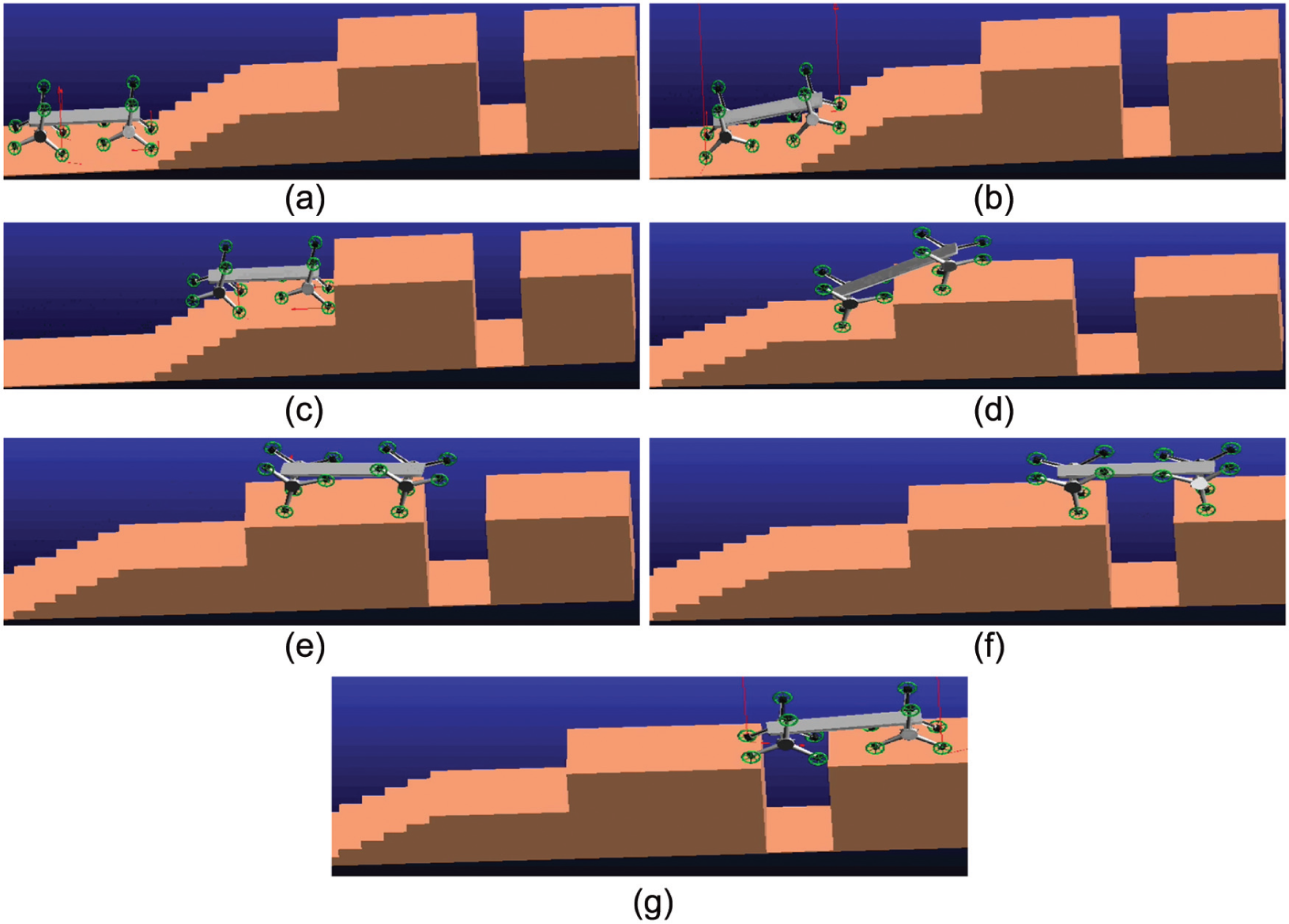
Simulation of combined obstacle overcoming: (a) before obstacle-overcoming, (b) staire-climbing, (c) finishing stair-climbing, (d) higher-step-climbing, (e) finishing higher-step-climbing, (f) ditch-crossing, and (g) finish ditch-crossing.
Conclusion
A kind of wheel-legged hybrid locomotion mechanism was put forward. In this article, the mechanical design was discussed, and the kinematic analysis and dynamic simulation of obstacle negotiation were made. Some conclusions can be drawn as follows:
This wheel-legged hybrid locomotion unit with the active transition system is valid and has better performance than that with the passive transition system.
The maximum obstacle-negotiation height is 750 mm, 60% of the locomotion mechanism height, and the maximum ditch-crossing width is 866 mm.
Footnotes
Academic Editor: Yong Chen
Declaration of conflicting interests
The author(s) declared no potential conflicts of interest with respect to the research, authorship, and/or publication of this article.
Funding
The author(s) disclosed receipt of the following financial support for the research, authorship, and/or publication of this article: This work is supported by the Fundamental Research Funds for the Central Universities (No. YX2013-14), the National Natural Science Foundation of China (No. 31200544), and Research Fund for the Doctoral Program of Higher Education of China (No. 20110014120012).