
Abstract
The use of robots to perform tasks in extreme environments instead of humans has gradually become important. For wider applications, robots should be able to adapt to complex environments, such as typical height/width-restricted motion spaces, raised obstacles, and ravines. The structure is the foundation of robot to move and perform tasks. In this study, a variable-attitude robot mechanism is designed and analyzed. With the link leg drive and Mecanum wheel drive, the robot has various configurations and omnidirectional motion capabilities. First, the design and analysis of the wheel drive system are performed, and the mapping relationship between the velocity of the robot and the velocity of the Mecanum wheel is clarified. Second, kinematics of the linkage drive system is analyzed, including the motion space, trajectory characteristics, and the effect of variable axle spacing on the robot motion performance. Subsequently, a simulation is used to verify the rationality of the three motion modes of the robot: walking, wheel drive, and hybrid drive. Finally, a motion simulation of several typical configuration changes in the robot is observed, and the feasibility of the robot mechanism to adapt to a complex environment is verified. This study contributes to the development and application of special advanced robots.
Introduction
Mobile robots are primarily used in dangerous and restricted spaces where they perform tasks on behalf of humans. Excellent mobility is required for robots to perform such tasks, and robots must be able to adapt to environments with different physical structures and sizes, such as environments with gullies and protruding obstacles, as well as restricted spaces. It is important to consider the structural improvement of a robot’s motion capability and complex environment adaptation capability during the design phase. There are two main design ideas: extending the robot configuration to improve the robot’s posture change capability and integrating multiple motion modes to extend the robot’s motion modality.
The first aim of this study was to improve the variable-pose capability of robots so that they can adapt to various motion scenarios with different conformations. Among them, folding and spreading robots with multiple morphologies in planes and spaces are typical polymorphic robots. Folding behavior, such as that exhibited by flower petals and the wings of flying animals, is common in natural organisms. 1 By simulating the biological structures and functions of plants, such as the way leaves fold 2,3 and the response of Mimosa to external stimuli, 4 researchers have designed numerous expandable mechanisms for applications, such as space deployable antennas and solar folding sails. 5 Inspired by the wing structure and unfolding behavior of insects, such as butterflies, 6 unicorns, 7 and earwigs, 8 researchers have conducted many studies on the design of foldable wing mechanisms. A foldable robot was developed that can move in a space of limited height and width owing to structural deformations, such as unfolding and folding. 9 A parallel robot with excellent deformation and folding capabilities in narrow and restricted motion spaces was proposed. 10 Metamorphic robots are also an important development direction. Since Dai and Jones proposed the theory of metamorphic mechanisms inspired by origami, some metamorphic mobile robots have been proposed. 11 Tang et al. developed a robot without disassembly and reassembly that could switch between different working modes, such as those that imitate the movement of reptiles, arthropods, and mammals. 12 A novel metamorphic parallel leg mechanism was created to improve the flexibility and adaptability of walking robots in unstructured environments. 13
The second idea incorporates multiple modes of movement, such as crawling, jumping, bipedalism, flying, and other typical movements, and has become a popular direction for development in robotics, recently. An amphibious robot with two modes of motion was designed that can land, crawl, and take off in the vertical plane. 14 A robot with the ability to fly like a bat and jump was designed, which not only allowed the robot to take off after jumping but also greatly expanded the robot’s movement space. 15 Kim et al. designed a robot that combines bipedal motion and flight motion, which not only helped improve the robot’s ability to cross obstacles but also improved the stability of the robot’s bipedal motion with rotor blades to the extent that the robot could even “step on a tightrope.” 16
The wheel has greatly facilitated the productivity of human beings, and further improvements and designs for the wheel are still in progress. Mobile robots represented by the Mecanum wheel as well as the omnidirectional wheel have gained application in the fields of storage and logistics, particularly since the outbreak of the new coronavirus, to avoid close contact between people. Omnidirectional mobile robots are significantly active in the fields of catering and health care but are limited by the inherent disadvantages of wheel drive. Currently, they are more often used in hotels, restaurants, factories, and other motion environments where the terrain is flat and simple. However, presently, vertical building construction has improved the living space of human beings and the efficiency of land use, and some equipment or instruments are gradually transferred from ground-floor buildings and factories to buildings, such as subway substations and research laboratories. To realize the safety inspection of buildings and other places, the demand for up- and downstairs functions is inevitable.
The maturity and widespread use of wheeled drive technology have influenced researchers to use the technology for achieving efficient motion of robots with extended overrunning capability. The wheel-leg combination is an effective implementation solution. A wheel-leg combination robot, Handle, which has excellent stability in terms of motion and is used in cargo handling and transportation, was proposed. 17 ANYmal was equipped with four torque-controlled wheels capable of traveling over challenging terrains, such as steps, slopes, and stairs, while overcoming these obstacles through dynamic motion. 18 A wheel-leg hybrid robot with four wheels and two front legs with a praying mantis leg shape can move in unstructured environments. 19
Herein, we designed a pose-changing robot that combined a leg-linkage drive system with a Mecanum wheel-drive system. After determining the structural characteristics of the robot, a kinematic analysis of the Mecanum wheel system and the linkage system was performed to obtain the structural and kinematic basis of the posture transformation of the robot. The feasibility of the hybrid operation of the robot linkage system and the wheel-driven system is verified through simulation, and the ability of the robot to climb stairs, cross gullies, and adapt to narrow spaces is verified in terms of configuration change.
Robot structure composition
As shown in Figure 1, the robot is structurally left-right symmetrical, consisting of a pitch-functional waist joint and six single-degree-of-freedom mechanical legs, with the left-right symmetrical mechanical legs sharing the same drive. Each mechanical leg is equipped with wheels at the end, of which the front and rear wheels are Mecanum wheels and driven separately, and the middle two wheels are passive auxiliary wheels, with a total of eight motor drives. The Mecanum wheel system has the characteristics of the all-round movement, and the robot linkage system can get a variety of configurations by changing the relative positions of the front, rear, middle wheels, and middle waist joint. The robot has three drive modes to match its configuration, including linkage walking mode, wheel drive mode, and hybrid mode.

Schematic diagram of the structure of a multi-configuration wheel-legged robot. (a) Schematic diagram of robot waist joint deformation; (b) schematic diagram of typical configuration transformation of the robot; (c) front view of robot mechanism; (d) side view of robot structure; (e) schematic diagram of robot linkage leg system; (f) Mecanum wheel system.
To adapt to the stepped obstacles shown in Figure 2(a) and to cross the threshold and narrow space shown in Figure 2(c), as well as the gully shown in Figure 2(d), the robot needs to have excellent motion capabilities. The robot’s linkage leg system has different axis spacing in different states, and the robot can cross gullies with twice the initial axis spacing width d 1 in different structural forms, as shown in Figure 2(b); at the same time, the robot can cross obstacles of height h 1 in the walking state, and obstacles of height h 2 based on waist deformation, as shown in Figure 2(e); it can fold and pass through narrow spaces with width and height of d 2 and h 3 (Figure 2(f)). The design and kinematics of the Mecanum wheel system and the robot linkage system are analyzed in more detail next.
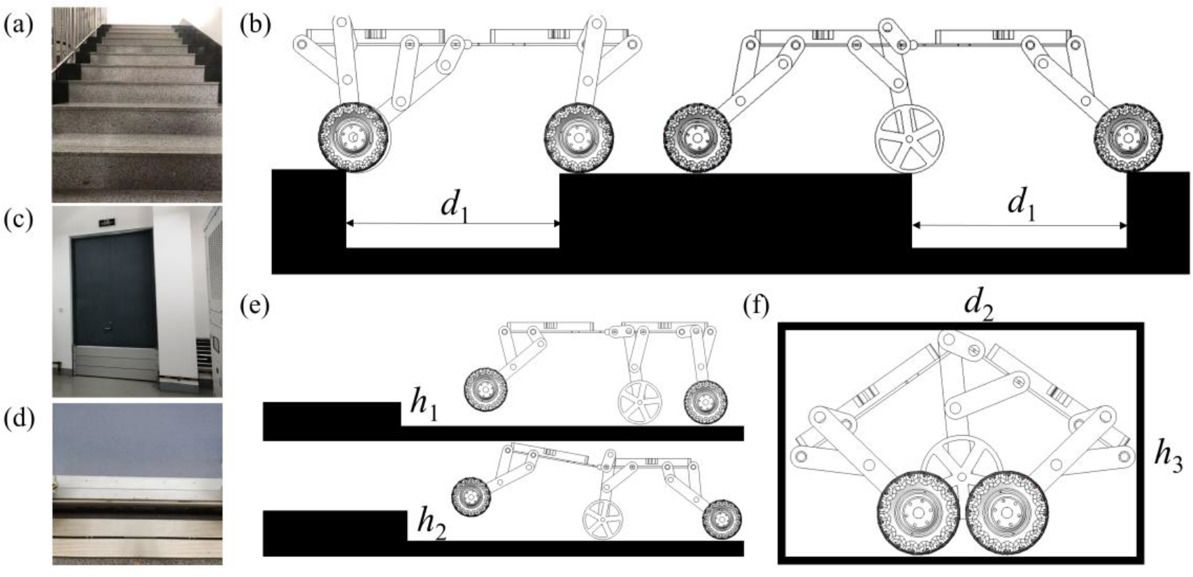
Schematic diagram of the robot adapting to a complex environment through conformational change. (a) Common stair step obstacle; (b) schematic diagram of robot’s conformation changes across a gully; (c) typical scenario with a threshold as well as narrow space; (d) gap between subway and platform; (e) schematic diagram of robot crossing an obstacle; (f) schematic diagram of robot’s movement in a narrow-restricted space.
Mecanum wheel system design and analysis
The installation of the Mecanum wheel drive system needs to follow the law that the left and right sides are symmetrical, and the diagonals are the same. When the robot moves forward and backward, the left and right lateral forces cancel out and the robot can move along a straight line, so there are two configuration options as shown in Figure 3(a). Taking the left front wheel of the robot as the object of force analysis, Fr is the axial force on the rotor in ground contact, and Ft is the tangential force on this rotor to drive the rotor rotation, Fr acts on the robot drive, which can be decomposed into the forward force Ff and the lateral force Fl . The lateral forces of the wheels on both sides of the robot cancel out and the forward and backward motions are achieved when the forward forces are the same, but the steering motion is limited in the second configuration because the force arm of Fr acting on the center of mass of the robot is shorter, or it can be explained by the opposite moments of Ff and Fl on the center of mass in configuration 2. This shows that the first configuration is more suitable for this robot.

Kinematic analysis of the Mecanum wheel system. (a) Mecanum wheel system configuration selection; (b) robot front-to-back movement decomposition; (c) robot side-to-side movement decomposition; (d) robot in-situ steering motion decomposition.
For the Mecanum wheel drive system, the relationship between the wheel velocity and the robot velocity can be obtained by the kinematic solution. As shown in Figure 3(a), the robot velocity V contains three physical quantities
The transfer relationship between the robot velocity V and the wheel linear velocity

Among them

The radius of each wheel is R and the rotational velocity is
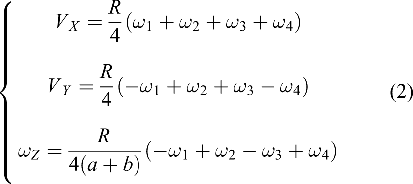
Different motion characteristics of the robot can be obtained by controlling the rotation velocity and direction of each wheel. Typical motions include the forward and backward movement of the robot (Figure 3(b)), left and right movement (Figure 3(c)), counterclockwise and clockwise rotation (Figure 3(d)), and so on.
Design and analysis of robot linkage system
The design of the robot leg structure, especially the design of the foot end trajectory based on the structural design, is the basis for achieving coordination between the robot linkage drive system and the Mecanum wheel drive system.
The relationship between the dimensions of the rods of the robot linkage leg system is shown in Figure 1(e). The design of a Hoekens mechanism combined with a parallelogram mechanism applied to a robot leg was proposed recently. 21 Inspired by this, the Hoekens mechanism is combined with the wheel drive, and the end trajectory of the Hoekens mechanism is a shell-shaped closed curve of a straight line and a circular arc, as shown in Figure 4(a) and using this special trajectory to realize the combination of the linkage leg drive and the wheel drive is the next focus of our research.
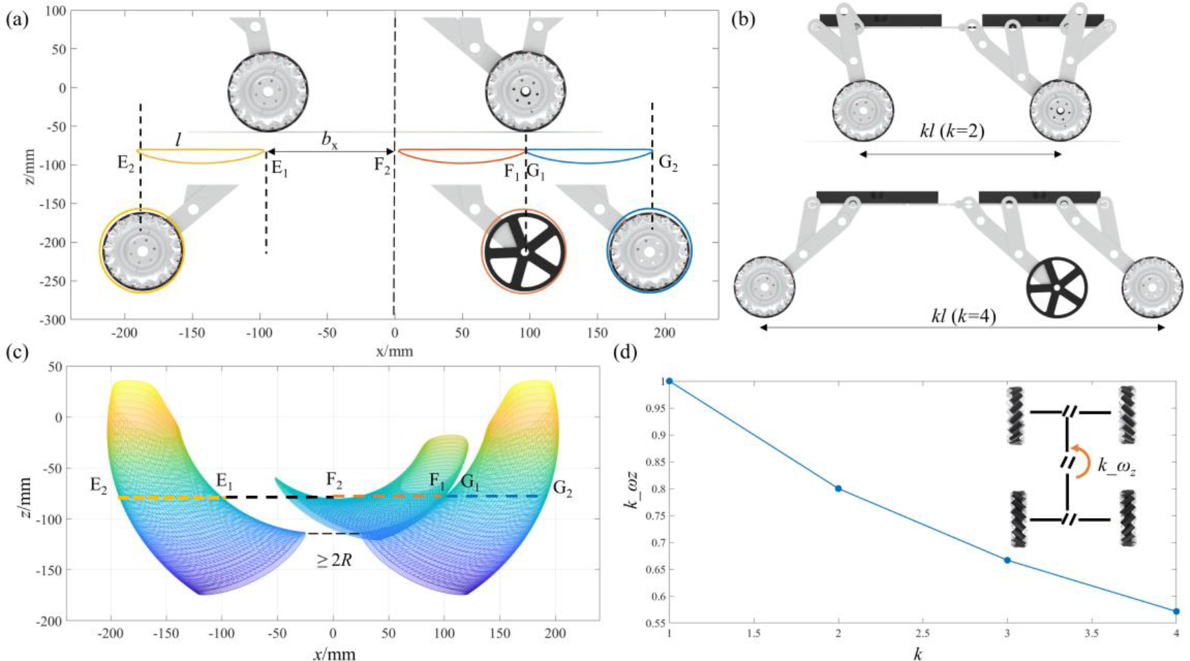
Kinematic analysis of the robot linkage leg system. (a) The trajectory of the foot end of each leg of the robot, where the linear length is l; (b) robot axis spacing, where the maximum axis spacing is twice the initial state when waist deformation is not considered; (c) motion space of robot foot when waist deformation is considered; (d) effect of robot axis spacing on steering performance.
The coordinate system is established with the geometric center of the robot torso as the origin, the forward direction is the positive x-axis direction, the vertical direction is the positive z-axis direction, and the y-axis direction is determined according to the right-hand rule. Because of the different mounting positions and forms of the three legs in the front and back, the kinematic solutions are carried out for all three legs in turn, and the coordinates of points E, F, and G are as follows


When the robot is moving and the waist is not deformed (
On the one hand axis pitch adjustment can change the overall rotation velocity of the robot, and as the axis pitch is reduced, the robot rotation velocity increases substantially (Figure 3(d)). On the other hand, increasing the axis spacing can effectively improve the robot’s ability to cross the gully, as shown in Figures 3(b) and 4(a), the robot can cross the gully with two times the initial axis spacing. During this process, the center of mass of the robot does not go up and down, and the motion is very stable.
The first requirement of the above is that the member length (l 2–l 5) of each linkage leg system in Figure 1 needs to meet equation (6).

Secondly, there are also requirements for the installation position of the middle leg (l 1 and l 6), and the coordinates of point F and point G need to meet the following requirements.

Robot to avoid interference mainly means, after the waist deformation, the front and rear position of the Mecanum wheel will not interfere, then the minimum distance between the front and rear wheels should be required to be greater than the diameter of the wheel (Figure 3(c))

The rod lengths l
2–l
5 are set to 100 mm, 50 mm, 125 mm, and 250 mm respectively, while l
1 and l
6 are 260 mm and 135 mm respectively, and the wheel radius is 75 mm to satisfy the equations (7) and (8), at which the waist joint swing angle
Verification of the rationality of wheel-leg hybrid drive
To verify the coupling effect of the robot hybrid system designed in this study, three driving modes of the robot, such as the wheel, linkage leg, and combination of wheel and leg, are simulated by the Adams virtual simulation platform. In the wheel drive mode, the linkage drive is locked, and the robot’s front, middle, and rear wheels are involved in the drive. In leg-drive mode, the robot is driven by the rear and middle legs, the front linkage leg drive is locked, the rear and middle wheels are locked, and the front wheels can be passively rotated. In the hybrid-drive mode, the robot is driven by the middle and hind leg linkages and the front, middle, and hind wheels, and the front limb linkage drive remains locked.
The initial state of the robot is shown in Figure 5(a), with the leg drive spindle velocity as

Simulation of three drive modes of the wheel-legged robot with wheel drive, linkage leg drive, and hybrid drive. (a) The initial shape of the robot in Adams; (b) horizontal movement velocity of the robot in the three drive modes; (c) tangential contact reaction force of the robot in the three drive modes; (d) normal contact reaction force of the robot in the three drive modes. The yellow curve in the figure indicates wheel drive, the blue curve indicates leg drive, and the green curve indicates hybrid drive.
As shown in Figure 5(b), the velocity of robot is stable under the wheel drive; although the motor also runs at a constant velocity during the rod drive, the corresponding robot velocity is in dynamic change; in the hybrid drive mode, not only the robot motion velocity is greater, but also the robot motion velocity variation is smaller than that of the rod drive. This shows that the hybrid wheel-legged robot designed in this paper has improved the velocity and stability of the robot compared with the traditional wheeled robot and the linkage-legged robot in terms of motion performance.
The wheel drive principle lies in the rotating wheel contact with the ground to produce forward frictional drive, and the wheel rotation in the opposite direction to produce backward frictional drive. Therefore, to improve driving efficiency, the contact reaction force between the end of the connecting rod structure and the ground when driven alone should be in the same direction as the direction of the wheel friction force. The normal contact reaction force is relatively small when the wheel is driven, so the linkage system should have less influence on the normal contact reaction force when it is involved in driving to avoid generating additional disturbance torque to the robot in the vertical direction.
By analyzing the robot contact reaction force pattern, it can be found that the tangential force of the robot is improved in the hybrid drive mode, which is why the robot motion velocity is improved. By analyzing the magnitude of the normal contact reaction force, it is easy to understand that the normal contact reaction force of the robot is the smallest in the wheel drive mode. The magnitude of the normal contact reaction force of the robot in the hybrid drive mode is not significantly different from that in the linkage drive mode, and the value of the contact reaction force is more stable. On the one hand, it confirms the availability of the Hoekens linkage leg system, and the robot contact reaction force is not characterized by a wave or trough variation in one cycle, but an almost constant normal contact force over a fairly long period, indicating that the robot is more stable during its motion and does not experience sudden up-and-down motion of the center of mass. On the other hand, it shows that this robot’s wheel-drive and leg-drive can be better integrated, which is the basis for the robot to meet the challenges of complex environments.
Robot configuration transformation simulation verification

Simulation of typical robot configuration. (a) Schematic diagram of robot adjusting axis spacing and leg lifting action; (b) schematic diagram of robot folding; (c) The vertical distance from points P1 and P2 (the front wheel center) to the ground during the configuration change; (d) body length dimensions of the robot when folding and changing posture.
As shown in Figure 6(a), the axis spacing of robot can be adjusted across the gully and can be increased by two times when the waist is not deformed, and the center of mass of the robot is very stable during this process, without obvious fluctuations. The robot linkage system drives the front leg to lift, and the middle and rear legs are supported in the arc area of the trajectory. The height of the front geometric center point
The robot can cross obstacles with a certain height, and two scenarios of the robot’s movement over obstacles were further simulated. In the first scenario, two consecutive obstacles were set to verify the robot’s ability to cross the obstacles; in the second scenario, staircase obstacles consisting of steps of different heights were set to verify the robot’s stair-climbing function and its adaptability to stairs of different heights.
The wheel diameter of the robot is d, and the two heights of the obstacles are h 1 and h 2, which are 0.3 and 0.5 times the wheel diameter, respectively, as shown in Figure 7(a) and (b). The horizontal and vertical displacements of the robot are shown in Figure 7(c) and (d). The blue and yellow curves correspond to the robot crossing successive obstacles and climbing the stairs, respectively. Figure 7(e) and (f) show the decomposition of the robot when it crosses the obstacles. The robot is unable to cross the above-mentioned obstacles without changing the axis distance in the wheel-driven state only. By changing the axis distance and with the leg linkage involved in the drive, the robot can even go over obstacles with a height of the wheel radius. There are two main reasons for this. On the one hand, the robot uses a wheel-leg hybrid drive, in which the rear and middle legs support and raise the front wheel while the front wheel is crossing the obstacle, and after the front wheel crosses the obstacle, it continues to support and raise the middle wheel together with the rear wheel, and similarly, the same rear wheel can also cross the obstacle. On the other hand, the adjustable axis distance of the robot can adapt to different obstacle-crossing situations, which also facilitates the hybrid wheel-leg drive of the robot. In the study of vehicle obstacle-crossing, it is known that the friction coefficient, front, and rear axle distances, and center of mass position all affect the obstacle-crossing ability of the vehicle.

Virtual simulation of robot locomotion in unstructured environments. (a) Robot crossing continuous obstacles; (b) robot crossing stair steps of different heights; (c) horizontal displacement of the robot; (d) robot vertical displacement; (e) robot over continuous obstacles timing diagram; (f) robot over stair steps timing diagram
The parameters are

Schematic diagram of a four-wheeled vehicle crossing a barrier. (a) and (b) show the robot’s front wheel overrun and rear wheel overrun states, respectively.
According to Yard et al., the larger the coefficient of friction the more favorable it is for obstacle crossing; for a four-wheel drive robot, the front wheel crossing ability decreases as
Conclusion
This study introduces a variable-attitude wheel-leg hybrid drive robot with two drive systems: linkage legs and Mecanum wheels. The linkage system drive enables stable axis distance adjustment, which not only facilitates crossing trenches with twice the initial axis distance but also adjusts the steering capability of the robot. The Mecanum wheel system facilitates all-round robot movements. The linkage and wheel drive systems can be driven separately, and the hybrid drive facilitates further improvement in robot motion performance. The waist joint helps to further change the robot configuration to improve its environmental adaptability when it crosses obstacles and faces narrow spaces. Future studies will focus on the development of robot prototypes. In addition, installing sensors (vision or force) will help the robot better perceive environmental information.
Footnotes
Authors’ note
Feng Hou and Jiwei Yuan contributed equally.
Author contributions
Software, KL; writing—original draft preparation, JY; writing—review and editing, FH; supervision, ZW; funding acquisition, FH. All authors have read and agreed to the published version of the manuscript.
Declaration of conflicting interests
The author(s) declared no potential conflicts of interest with respect to the research, authorship, and/or publication of this article.
Funding
The author(s) received financial support for the research, authorship, and/or publication of this article: This research was funded by National Key R&D program of China (2017YFB1200801).