
Abstract
The Super-FRS, Superconducting Fragment Separator, is a unique machine that presents several challenging technical problems. One of these is regarding how to conduct maintenance in the target area where high levels of radiation will be generated and human access is forbidden. To address this problem the use of a remote maintenance system is foreseen. The objective of this paper is to develop a systems engineering (SE) research and development (R&D) approach suitable to develop the Super-FRS Target Area Remote Maintenance Systems (TARMS) and the RH design adaptation of the components in the target area. The Super-FRS target area is described in detail in order to introduce the need for a remote maintenance system. Components in the target area are classified by adopting ITER RH maintenance classification. The general scenario of remote handling and the current target area remote maintenance system are described. Finally, the proposed systems engineering approach is presented.
Keywords
1. Introduction
Around the world there are many accelerator facilities employed to conduct scientific experiments; such experiments provide a better understanding about the structure of matter and the universe. This has led to the development of many applications in fields like health care, national security, environmental protection, energy and industry. In order to provide the state-of-the-art accelerator facilities necessary to conduct novel precision experiments, facilities are permanently being improved in order to produce beams of higher energies and intensities. This has several implications for designing, maintaining and operating the devices for the new accelerator facilities. In addition, higher levels of radiation are generated and radiation protection becomes more critical and difficult. It is then when remote handling (RH) becomes a key technology for the operation of the new accelerator facilities.
The Helmholtz Centre for heavy Ion research (GSI) is a large-scale accelerator facility, located in Darmstadt, Germany. The main research program of GSI focuses on the field of nuclear physics and atomic physics, but applied research in the areas of materials, plasma physics, biophysics and nuclear medicine is also conducted. The GSI accelerator facility is currently transformed into the new Facility for Antiproton and Ion Research (FAIR). This accelerator facility will supply rare isotopes and antiproton beams of unprecedented intensity and quality [1].
The existing GSI and the future FAIR facilities have a fragment separator, the FRS and Super-FRS respectively. The Super-FRS represents a major component of the FAIR facility. It is an in-flight particle separator where rare isotopes of all elements (up to uranium) will be produced and separated within few hundreds of nanoseconds, allowing the study of short-lived nuclei [2]. The Super-FRS is divided into two main sections: the Pre-Separator and the Main-Separator, as shown in Figure 1.

Lay out of the Super-FRS [3]
The FRS and the Super-FRS host a target area in which high levels of radiation are generated. Due to radiation human access to those areas is restricted; in the case of the FRS human intervention in the target area is possible after a cooling time has passed and the necessary safety measures are taken. In contrast, based on current simulations regarding the amount of radiation that will be generated inside the Super-FRS target area [4], it is foreseen that human access will be totally forbidden. In any case, an RH system is required to conduct maintenance and inspection interventions. The existing concept of RH for the Super-FRS target area is based on a vertical plug system very similar to the one utilized at the Paul Scherer Institute (PSI) in Switzerland [5].
Section 2 provides a description of the Super-FRS target area and the plug system. Section 3 presents a classification of the main components in the target area based on the ITER RH maintenance classification. The general scenario of RH for the components in the target area is presented in Section 4. Section 5 describes the existing conceptual design of the Super-FRS Target Area Remote Maintenance System (TARMS). Finally, in Section 6 a systems engineering R&D approach to develop the TARMS and the RH design adaptation of the target area components is presented.
2. Super-FRS Target Area
The first halve of the Pre-Separator region of the Super-FRS is the target area; this is a very critical zone due to the levels of radiation that will be generated. Special considerations [4] like adding beam catchers and dividing a dipole stage into three dipole units have been taken in developing the layout shown in Figure 2. The approximate length and height of the target area are 25m and 5m, respectively. All components in the target area are surrounded by iron and concrete shielding in order to lower the radiation dose rates in nearby areas.
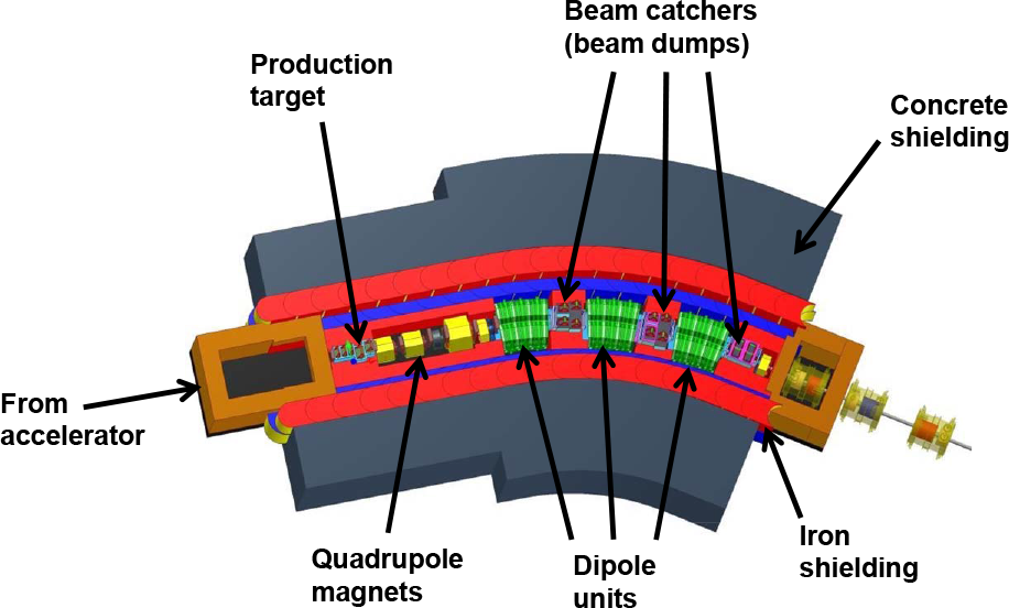
Target area layout showing the concrete and iron shielding and its main components
At the beginning of the target area there is a vacuum chamber that contains the high-power production target, some detectors and a collimator. After the vacuum chamber, there is a triplet arrangement of quadrupole magnets. In addition there is a dipole stage divided into three dipole units allowing the installation of vacuum chambers containing beam catchers (beam dumps) at specific positions between the individual dipole units. All magnets are designed to be radiation resistant based on an estimated annual dose of ≈10 MGy (considering an operational time of 4000 hours/year) [2].
On top of the magnets and the vacuum chambers there is a working platform where the more radiation sensitive devices are located. The shielding in the target area is such that manual maintenance to the devices on the working platform (e.g., electric drives and vacuum pumps) is possible.
2.1 Activation in the target area
In [4] a setup was simulated with the heavy ion transport code FLUKA in order to know the activation of the components in the target area. The scenario is based on irradiation with a 1.5 AGeV 238U beam of 1012 particle/s during four periods of 90 days with a following cooling time of 120 days. Refinements have been done to the previous setup (e.g., adding pumping ports); the new results are shown in Figure 3. The prompt dose refers to when the beam is on and is passing through the target area. The dose by activation refers to the dose generated by activated components. Higher activation is presented in the beam catcher (BC) receiving most of the primary beam.

Distribution of ambient dose rate H*(10) shown in a cut of the target area. The primary beam is dumped after penetration of the target in the indicated beam catcher (BC).
The prompt dose rate is 100,000 times higher than the dose by activation. For maintenance considerations of the components in the target area, only the dose by activation is of interest. While the dose by activation in the beam catcher goes up to 5 Sv/h, the level in the working platform reaches only about 10 µSv/h.
2.2 Target Area Vertical Plug System
To achieve low activation on the working platform a close shielding all around the beam path along the target area is required. This imposes a technical problem regarding how to access (for example to conduct maintenance tasks) the devices that directly interact with the beam such as detectors, targets and beam catchers.
A solution for this problem is by means of a vertical plug system; this is an already proven concept and has been used in many facilities [5][6]. As mentioned earlier the vertical plug concept chosen for the Super-FRS target area is very similar to the one in PSI. The concept comprises a combination of vertical beam-line inserts (target, beam catchers, slits, diagnostics detectors and others) with massive mobile shielding assembled into a vacuum chamber, as shown in Figure 4.

Vacuum chamber showing five plugs. At the bottom of the plugs can be seen the devices along the beam path. In this case (from left to right) there is a detector, an empty plug, another detector, the high-power production target wheel and a collimator.
Each plug insert can be removed vertically from its vacuum chamber and handled as one unit. At the bottom of each plug there is normally a beam interaction device (BID). Figure 5 depicts the plug with the high-power production target wheel.

The main parts in a plug: the beam interaction device (BID), mobile shielding (iron and concrete), on top the devices more sensitive to radiation and the lifting-hook
In general the plugs are all different in size and weight. On average, the plugs have an approximate total height of 3400mm; the height of the mobile shielding is 1970mm and the lifting hook at the top of the plug has an approximate height of 1100mm. The weight of the plugs varies depending on their size; the heaviest plug weighs roughly 7500kg.
In total the target area has four big vacuum chambers; the one shown in Figure 4 and three more hosting plugs with beam catchers. Figure 6 shows the components in the target area, the shielding has been removed in this figure for a better view.

Target area components. From left to right there is the vacuum chamber hosting the production target, then the triplet arrangement of quadrupole magnets and finally three dipoles units having in between the vacuum chambers hosting beam catchers.
Since only 10 to 50% of the primary beam will be converted in the production target, the remaining primary beam has to be stopped because high power pulses can destroy the steel vacuum chambers in one shot. Dedicated devices called beam catchers (beam dumps) are foreseen to stop the primary beam.
The beam catchers have two main objectives. One is to absorb the kinetic energy of the heavy ions that does not interact with the production target. The second is to shield the following parts of the separator from high levels of secondary radiation [4]. Since energy absorption and shielding require different types of materials [3], two successive types of beam catchers, as shown in Figure 7, are foreseen.

Plugs with beam catchers. The V shape beam catcher for energy absorption (left) and the massive iron block for shielding of fast neutrons (right).
The catcher close to the entrance of the vacuum chamber is made of graphite (for energy absorption) and aluminium; it has a V shaped opening. It is required to be cooled with a coupled heat sink by water-cooling. Behind is a solid rectangular shape beam catcher made of iron for shielding. Certain beam catchers require one or two degrees of motion (vertical and horizontal).
3. Target Area Components Requiring Remote Handling
During the design phase of accelerator facilities, several studies are conducted to estimate the levels of radiation that will be generated. The results indicate the highly activated components making where to apply remote handling techniques obvious. Besides identifying which components require RH, it is important to define priorities for the development of RH tools and techniques for each component.
3.1 Remote Handling Maintenance Classification
This paper uses a components classification defined by ITER [7] as an approach to classify the components in the target area of the Super-FRS. Such classification helps to define priorities for the development of RH tools and techniques for each component. The classification comprises four classes of components:
RH class 1 = components requiring regular planned replacement
RH class 2 = components that are likely to require repair or replacement
RH class 3 = components that are not expected to require maintenance or replacement during the lifetime of the facility but would need to be replaced remotely in case they fail
RH class 4 = components that do not require remote handling
3.2 Classification of the major components in the target area
The components in the Super-FRS target area were assigned to a component class. Table 1 shows the classification; many major components were assigned to RH Class 3. The plugs are the only major components with three different RH classes assigned.
RH class for each major component in the target area

3.2.1 RH class 4 components in the target area
Because the working platform is a place for hands-on intervention, all components in the working platform are considered RH Class 4. Additionally, the plugs have some components of RH Class 4; the ones located at the top of the plug, which are at the working platform level. These are shown in Figure 5 as devices more sensitive to radiation.
3.2.2 RH Class 3 components in the target area
Most of the major components in Table 1 were assigned to RH Class 3. The main reason for this is that these components are designed and developed to be radiation resistant [3]. These components are required to be highly reliable and it is assumed that they will not fail during normal operation. One recommendation about these components made in [7] is that preliminary maintenance schemes should be studied.
3.2.3 RH Class 2 components in the target area
All components along the mobile shielding used to transport cooling water and electrical signals, as well as to transfer motion to the BIDs are assigned to RH Class 2. All of these components are considered of low complexity and low probability of failure (hoses, pipes, cables, rods and shafts among others).
One concern about generalizing all components along the mobile shielding to this class is the fact that components at the bottom of the shielding will be more activated than the ones at the top. This is an important consideration because depending on what type of component is at the very bottom; the operational environment can reduce its lifetime, making a possible jump from RH Class 2 to 1. For the purpose of this initial classification, to generalize is acceptable. Later, based on more information about the components, a detailed classification will be conducted.
3.2.4 RH Class 1 components in the target area
All components in the BIDs are considered as RH Class 1. These components are subjected to a demanding operational environment: radiation, high-energy deposition and vacuum (meaning no lubrication for moving parts) among others. These components will thus be the most activated, presenting high levels of wear even during normal operation.
Regular maintenance will be required and all activities have to be conducted using RH equipment. In order to keep the scientific facility running for several years, RH strategies have to be developed to conduct maintenance on RH Class 1 components.
4. Remote maintenance scenario in the Super-FRS target area
In order to provide maintenance for the RH Class 1 and 2 components in the target area, plugs have to be retrieved from their vacuum chambers and send to a dedicated place (a hot cell) where RH maintenance tasks can be performed.
4.1 RH transfer of the plugs
The remote handling scenario to transfer a plug from a vacuum chamber to the hot cell is depicted in Figure 8. The first step is to remove concrete shielding blocks on top of the working platform, such blocks are required when experiments are running in order to shield against prompt radiation.

Handling scenario for transferring a plug from the target area to the hot cell
Once the working platform is accessible different media connections (e.g., vacuum, water cooling and electricity among others) linked to the plug of interest are disconnected manually. Then a bridge-like support structure (see Figure 8) is installed. On this bridge, a transfer-shielding flask can be supported. Once the flask is properly mounted a sliding door at its bottom is opened. A lifting mechanism is deployed and hooked to the plug and then the plug is vertically retrieved from the vacuum chamber. When the plug is inside the shielding flask the sliding door is closed and by means of an 80-ton crane, the shielding flask is transported to the hot cell.
In the roof of the hot cell there is a docking port on which the shielding flask is mounted, after this the sliding door is opened and the plug is lowered down to a dedicated holding fixture that clamps the plug in a reliable and safe position.
4.2 RH maintenance of the plugs
Once the plugs are inside the hot cell (one at a time) dedicated RH equipment is used to conduct maintenance tasks (Figure 9). Plugs have to be designed considering and incorporating RH features that allow the operator by means of RH equipment to conduct remote maintenance activities. Common RH maintenance activities inside the hot cell are the exchange of worn RH Class 1 and 2 components. Next to the hot cell there is a storage cell planned for the disposal of old parts and components.

A plug inside the hot cell can be remote maintained by means of two master-slave mechanical manipulator arms, one power manipulator and dedicated tools
Transferring and conducting RH maintenance and disposal activities to the plugs and their components requires dedicated RH equipment. Such equipment includes custom and off-the-shelf (OTS) devices. A detailed description of the RH equipment foreseen for the target area is presented in the following section.
5. Target Area Remote Maintenance System (TARMS)
The target area remote maintenance system (TARMS) comprises three main subsystems: housing, manipulation and transferring, each of those consists of some major components. Table 2 shows the TARMS sub-systems and their major components. The concept of TARMS is taken from the PSI remote handling of Target-E and the hot cell.
TARMS sub-systems and components

5.1 Housing sub-system
The housing sub-system refers to dedicated places in which it is possible to manipulate and handle activated parts. The identified components are the hot cell and the storage cell. Inside the hot cell it is planned to conduct maintenance activities. The storage cell will store activated parts coming from the hot cell. The conceptual design of the hot cell and storage cell developed by Siempelkamp Nukleartechnik GmbH is shown in Figure 10.

Hot cell on the left and storage cell on the right
Both cells host components of the manipulation subsystem. Each has one pair of master-slave mechanical manipulators mounted on the wall frames of radiation safety windows. The hot cell and storage cell also have interfaces to place new components inside them.
A double lid port with a conveyor connects the two cells. Such a handling device is used to transport barrels filled with activated parts (waste) coming from the hot cell. Once a barrel is full, it will be properly sealed and transported by a crane to a storage place made of tubes inside the concrete floor of the storage cell. After further cooling down of radioactivity many such barrels can be assembled in a disposal unit for external storage.
5.2 Manipulation sub-system
The manipulation sub-system refers to all devices that provide the means for an operator to work with activated parts. These are manipulator arms, handling devices and tools. In this application four master-slave mechanical manipulator arms and one power manipulator are planned for (Figure 11).
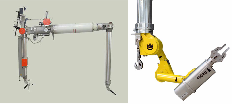
Master-slave mechanical manipulators have been used to manipulate activated parts since the 1940s. These manipulators are radiation tolerant. Some of the benefits in using such manipulators are that they are reliable and easy to use and to maintain. The drawback is that most of the physical work has to be performed by the operator, making it more difficult and tiring to conduct maintenance tasks.
The power manipulators typically have five to seven degrees of freedom and are electrically driven as well as radiation resistant. This type of manipulator arm is normally installed in a telescopic boom mounted on a bridge-crane carrier installed in the top of the hot cell. This way the power manipulator workspace covers almost the entire hot cell volume. Contrary to the simple master-slave manipulators they can be used for heavier equipment.
The handling devices refer to equipment necessary for handling activated parts but are not considered as manipulators. These are the movable platform with the fixture to hold the plugs inside the hot cell (shown in Figure 9), the conveyor with the double lid port system, a crane and a lifter inside the storage cell.
At the moment only general-purpose tools are considered. These are for example: grippers, wrenches, a cutting grinder and bow saws and screwdrivers. The idea in identifying RH Class 1 and 2 components is to understand the type of maintenance activities that must be conducted in order to develop proper tools and procedures.
5.3 Transferring sub-system
The transferring sub-system stand for the system is required for transferring one plug from the target area (vacuum chamber) to the hot cell and vice versa. Two components were identified, the transfer-shielding flask and the bridge like support structure.
The transfer-shielding flask is dedicated equipment utilized to retrieve the plugs from the vacuum chambers and transport them to the hot cell. Because a dose rate up to many Sv/h is foreseen close to the BIDs (Figure 3), the transfer-shielding flask provides shielding for human access on the outside to ensure a safe transfer. The wall thickness is tapered towards the top because at the top the plug is much less activated. This component has many sub-components and functions like opening ports, guiding mechanisms and lifting mechanisms.
The bridge-like support structure component is the interface between the working platform (target area) and the transfer-shielding flask (RH equipment). Because of this, the design should be fully compatible with both major components.
6. Systems Engineering R&D approach for the development of the TARMS and the RH adaptation of the plug system components
The proposed approach is to develop the TARMS and the RH adaptation of the target area plug system components. The R&D approach is based on systems engineering principles; it comprises six processes, as shown in Figure 12. The first process (components analysis) receives as inputs the latest designs of the target area plug system components and TARMS.
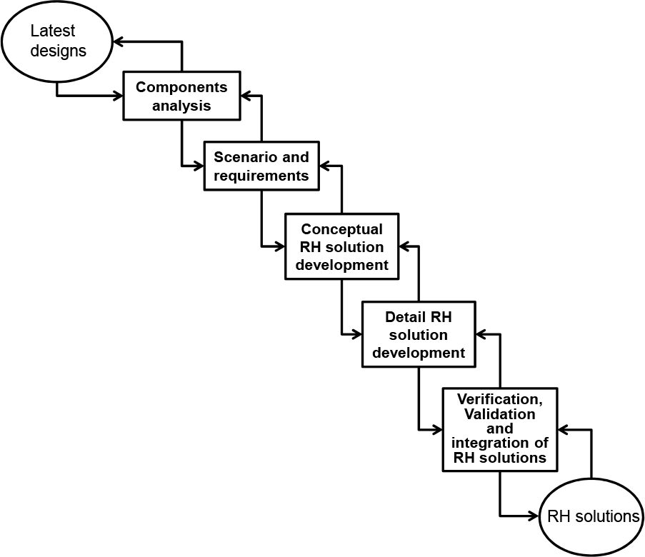
Phases of the systems engineering R&D approach
The approach addresses the problem of coping with changes in the component designs (plug system) once the RH solutions are under development. This has been addressed according to [10] by definition of the order of magnitude of the requirements parameters with respect to tolerance margins. Based on this solution we have proposed considering flexibility and variety in the development of the RH solutions and RH design adaptation respectively. Certain activities within the processes of the proposed approach are dedicated to track and address the design changes of the plug system components (RH Class 1 and 2).
6.1 Components analysis
In this process, an in-depth analysis will be performed to obtain a good understanding of the current development of the target area plug system components and TARMS. The main activities of this process are:
Understand and define the actual development of the plug system and TARMS
Develop a functional analysis for an in-depth understanding
Analyse the procedures of assembly and disassembly of the components
Analyse components interfaces
Classify components into mature or under development
6.2 Scenario and requirements
The requirements will be developed based on RH scenarios to conduct RH maintenance tasks. The main activities of this process are:
Define RH maintenance tasks
Detail classification of components based on ITER RH maintenance classes
Define development priorities
Develop RH maintenance scenarios
Initial RH components assessments
Preliminary RH requirements, e.g.
Tooling
Equipment
Definition of sizes and weights
6.3 Conceptual RH solution development
In this process, the concept of each RH maintenance task will be developed and tested by means of virtual reality (VR) simulations. The main activities in this process are:
Develop preliminary RH solutions, definition of:
RH equipment
RH tools
RH techniques
RH sequences
Develop preliminary adaptation of the designs
Consider possible changes in the components designs (add flexibility to the preliminary RH solutions)
Consider different RH adaptation concepts of the components based on possible changes
Develop VR simulations for the RH tasks
Identify RH concepts and solutions that have to be tested on real prototypes
Update RH requirements
6.4 Detail RH solution development
This process is to detail procedures and sequences and also to develop and build prototypes to conduct RH tests. The main activities in this phase are:
Develop detail RH solutions
Detail adaptation of the designs
Evaluate possible changes in the components designs
Evaluate the different RH adaptation concepts
Develop and build prototypes for RH testing
Update RH requirements
6.5 Verification, validation and Integration of RH solutions
The developed RH solutions and concepts have to be tested in order to assure reliability. Partial and initial RH solutions and concepts will be verified and validated. All validated solutions and concepts will be integrated into the final RH solutions. The main activities in this phase are:
Verify and validate preliminary and partial RH concepts and solutions
Verify and validate RH design adaptation of the designs.
Integrate validated RH concepts and partial solutions into final and complete RH solutions
Verify and validate final RH solutions
Finalize RH requirements
The proposed approach is iterative; this means that several passes through the five processes will be performed along the development of the TARMS and the RH design adaptation of the plug systems components.
7. Discussion and Conclusions
In this paper, we have proposed a systems engineering research and development approach for the development of the TARMS and the RH design adaptation of the target area plug systems components. A description of the facility was given in order to have a good impression of the problem and why it requires a remote handling system. The major components in the target area were classified according to ITER RH maintenance classification. In addition, the conceptual scenario of remote handling in the target area, as well as the TARMS, were described.
The first inputs of the SE R&D approach are the latest models of the plug system components and the TARMS. The plugs and BIDs are at the moment under development and different design solutions are in progress and under evaluation; all models are at the moment at the level of preliminary designs. At the same time the RH concept of the plugs and BIDs is being developed. Commercial OTS and custom RH equipment is foreseen to conduct remote maintenance.
One of the main goals in applying the proposed approach is to develop the RH requirements for the detail designs of the plug system components and TARMS. In this manner the plug system final designs will be designed to be remotely maintained by the TARMS. Both systems will be fully compatible.
In conclusion, RH is a key technology in ensuring the availability of the Super-FRS machine during the operational time of FAIR. Classifying components is a good approach to focus the engineering effort developing RH tools and techniques for specific components.
By defining RH scenarios, component interfaces are identified. These are very important in order to ensure compatibility between the TARMS and the plug system. This is done with the intention of minimizing risks and unforeseen situations.
Changes in the plug system components have to be considered as long as the components are still under development. Flexible and simple RH solutions and RH design adaptations shall be pursued.
Footnotes
8. Acknowledgments
The authors thank the FP7 Marie Curie Initial Training Network PURESAFE (grant agreement 264336) for funding and support.