
Abstract
This study covers new trends and techniques in the field of predictive maintenance, which has been superseding traditional management policies, at least in part. It also presents suggestions for how to implement a predictive maintenance programme in a factory/premise and so on. Predictive maintenance primarily involves foreseeing breakdown of the system to be maintained by detecting early signs of failure in order to make maintenance work more proactive. In addition to the aim of acting before failure, it also aims to attend to any fault, even if there is no immediate danger of failure, to ensure smooth operation and reduce energy consumption. Predictive maintenance has been adopted by various sectors in manufacturing and service industries in order to improve reliability, safety, availability, efficiency and quality as well as to protect the environment. It also has created a separate sector, which specializes in developing predictive maintenance instruments, offering dedicated predictive maintenance solutions and training predictive maintenance experts. Predictive maintenance techniques are closely associated with sensor technologies but for efficient predictive maintenance applications, a comprehensive approach, which integrates sensing with subsequent maintenance activities, is needed to be adapted in accordance with the needs of the particular organization. Recent advances in information, communication and computer technologies, such as Internet of Things and radio-frequency identifications, have been enabling predictive maintenance applications to be more efficient, applicable, affordable, and consequently more common and available for all sorts of industries. Researches on remote maintenance and e-maintenance have been supporting predictive maintenance activities especially in unsafe working environments and scattered locations.
Keywords
Introduction
Predictive maintenance (PdM) is the latest maintenance policy around and has been adopted by many sectors, especially more by the ones where reliability is paramount, such as power plants, utilities, transportation systems, communication systems and emergency services. In essence, it foresees faults or failures in a deteriorating system in order to optimize maintenance efforts by means of evaluating state of the system mostly and/or, in a broader sense, by means of historical data of the system in hand. A PdM programme primarily detects early signs of fault or failure and then initiates maintenance procedures at the right time. PdM data provide both diagnostics and prognostics information, 1 telling what is wrong, where the problem is, why it is happening, whether it indicates a failure or just a fault and when failure is going to happen, if any. Thanks to all these information derived from PdM data, maintenance works become more proactive, and thus effective and efficient. Additionally, and secondarily, that PdM data give prognostic information also lends PdM techniques to be utilized for applications other than maintenance, such as estimation of fuel cell operating time, 2 evaluating quality of second-hand products 3 and cutting tool wear evaluation. 4
The concept of PdM was reported to be around since 1940. 5 However, its rudimentary version, where an experienced maintenance person tours the premise and uses his or her senses of seeing, hearing, smelling and touching to detect a sign of a problem, dates further back and it is still being widely practiced because it is still very valuable in many cases. What has changed, evolving into PdM that we know of today, is that there are now sensors available for the ‘seeing, hearing, smelling and touching’ tasks and that the concept of state evaluation has been elevated from component and machinery level to system level. In its most integrated form, PdM gathers data about the conditions of the system mostly by sensors, nowadays more and more by Wireless Network Systems (WNS), and evaluates the data, then determines the right time to intervene, and activates and conducts the necessary maintenance procedures, such as mobilizing personnel and spare part order. Consequently, PdM efforts require interdisciplinary approach that involves engineering and management methods.
A PdM programme basically consists of three main steps: data acquisition, data processing and maintenance decision-making. 1 Consequently, researches on PdM are being conducted on these three subjects, plus on dedicated PdM techniques and on specific sector/machinery/component to be maintained. This study discusses PdM from technical and managerial points of view by first describing the concept of PdM together with other management policies, subsequently covering the latest PdM techniques available, then outlining some important points that should be taken into consideration for a successful PdM implementation and, in the end, reporting the latest developments and future trends in PdM.
Other management policies and PdM
PdM is considered by many to be the latest policy in the evolution of maintenance management and its value can be best appreciated when compared with traditional management policies, which are now considered inadequate on their own. Therefore, it is only logical to introduce the topic of PdM by first defining the other maintenance policies, which it has been superseding in great deal. Although there are considerable overlapping areas between them, 6 it is still useful to give their definitions and differences between them. Despite the fact that there are other classifications of maintenance policies according to different classification considerations7–13 and many more, the following classification has been rather well established in the industry:
Corrective maintenance (or unplanned or run to failure or failure-based or failure-driven or breakdown or fail to fix or reactive maintenance): it simply refers to allowing an item to run until it fails and then restoring it. This can only be afforded if the consequences of failure are insignificant. It is important to note, as put by Gross, 14 that ‘The success of the maintenance operation must be measured in uptime and not how many breakdowns get repaired’.
Preventive maintenance (or time-based maintenance (TBM) or routine or periodic or interval-based or time-directed or planned maintenance): maintenance work is scheduled in advance to prevent failure, based on either calendar time or equipment-operation time. The maintenance frequency is determined according to manufacturer’s guidance mostly or experience.
PdM: PdM work is based on information that indicates deterioration, which may result in more energy consumption only and/or, in more progressive cases, will result in failure. In other words, PdM not only aims for failure prevention but also for efficient operation, hence improved safety, product quality, reliability, availability and reduction in energy cost. Failure prevention aim of PdM is of primary concern, compared with the aim of efficient operation of PdM and, consequently, most PdM works focus on early signs of failure and taking precautionary measures accordingly. It is useful to know that 99% of the machine failures are preceded by some indicators15,16 PdM, in essence, detects these indicators in order to perform necessary maintenance work at the right time either by means of constantly monitoring the machinery/system/equipment/component/structure/asset or examining/probing it at regular intervals or continuously.
The main difference between PdM and TBM is that in the case of TBM, sometimes failure may occur before the scheduled maintenance, creating catastrophic results in some cases, or sometimes the system is stopped to do the maintenance just because it was planned to do so, causing unnecessary downtime and/or part replacement. The following example illustrates limitations of TBM approach clearly. 17 A total of 30 identical bearing elements were tested under identical conditions by SKF Group. The bearings were stressed to fail and then the time of failure is recorded. The time-to-failure results were found to vary between 15 and 300 h, exhibiting such a wide distribution that it becomes impossible to foresee failure time, hence set the right maintenance interval. Therefore, the condition of each component/equipment and so on should be evaluated individually, and then, the timing of maintenance should be determined according to the evaluation results, which is the essence of PdM. Although there are works that aim to reduce the number of maintenance operations of periodic maintenance, 18 PdM is the most developed maintenance policy and avoids over-maintenance or under-maintenance.
Although PdM can be further divided into two as statistical-based PdM and condition-based PdM, 19 it is very common to treat PdM and condition-based maintenance (CBM) as synonyms. PdM activities are mainly based on the current situation of the system, rather than predicting the future by using statistical data about the past. PdM data are mostly obtained by examining the system periodically or monitoring constantly by various sensors, but less by evaluating previous performance of the plant, physical models or average life statistics. PdM can be described as evaluation of health of the system 20 for a proactive and efficient maintenance, underlying the very essence of PdM. It should be acknowledged, however, that there are cases when the aforementioned division is necessary, especially in determining frequency of PdM examinations.
It is worth reporting that in some recent publications, proactive maintenance, which is applied to eliminate the root causes of failures, 21 is mentioned to follow PdM as the next stage in the evolution of maintenance. However, since in practice PdM applications do not just do the necessary maintenance work at the right time but also continue and question root causes, treating proactive maintenance as a separate and new maintenance policy can solely serve the purpose of emphasizing the importance of root cause analysis and the further maintenance activities based on that analysis. In addition to the above approach, that is, defining another type of maintenance that is beyond PdM, CBM+ was reported to be another type of maintenance: ‘The CBM+ includes RCM analysis other than regular CBM component’, RCM denoting reliability centre maintenance. 22
The advantages of PdM can be summarized as follows:
Improved worker and environmental safety
Higher reliability
Higher availability
Improved product quality
Less costs for parts and labour
Less waste in terms of raw materials and consumables, such as lubricants
Energy savings from smother machines (e.g. alignment claimed in some cases, 3%–5%; balancing 1%–2%) 23
The followings are industrial average savings, thanks to a functional PdM programme: 24
Return on investment: 10 times;
Reduction in maintenance costs: 25%–30% (since maintenance costs account for 15%–70% of total production cost, considerable amount of savings can be achieved by PdM 25 );
Elimination of breakdowns: 70%–75%;
Reduction in downtime: 35%–45%;
Increase in production: 20%–25%.
As pointed out earlier, PdM starts with ‘sensing’ the situation of the system, and various types of techniques have been developed specifically for PdM purposes. PdM techniques can be classified as follows:
Process parameter measurements
Vibration analysis
Oil analysis
Thermal analysis
Acoustic analysis
Others
In addition to the field of ‘sensing’, mentioned above and detailed later, making decisions in PdM is another aspect that requires a different field of expertise. Research in this aspect of PdM ranges from works on maintenance policy selection 26 to multi-level decision-making for the PdM. 27
It should be noted that PdM in general is based on the following two main premises:
Deterioration rate is low enough to allow time to detect and analyse the failure signs and then to intervene.
Leaving the system to fail is not affordable in terms of safety and/or cost.
PdM techniques
Although visual inspection and human senses provide valuable information related to the state of the system to be maintained, PdM heavily relies on sensor technologies. All these PdM efforts have led to create dedicated PdM techniques, which will be discussed in this section. These techniques can be broadly categorized into six: process parameter measurements, vibration analysis, oil analysis, thermographic analysis, acoustic analysis and other PdM techniques.
Measuring process parameters that indicate performance
Process efficiency, heat loss, temperature, motor current, fluid pressure, humidity 13 and flow rate are some of the many process parameters that are measured to monitor health of the system. Any abnormal changes in process parameters as well as changes in production rate and product quality can give information about health of the system. However, it must be noted that the changes in process parameters are sometimes caused by operational changes, such as speed and load, but do not necessarily indicate a developing fault.
Vibration analysis
Vibration analysis is the most common PdM technique and used mostly in rotating or reciprocating equipment either on continuous basis or at scheduled intervals to obtain information state of the system. For example, vibration that takes place at the running speed indicates imbalance or misalignment and vibration levels at several times the rotating speed indicates impending bearing problems. 28 Similarly, an excitation frequency of n × r/min indicates problems that could be associated with n blades, n gear teeth, n balls or rollers in a bearing or n cylinders on a pump. 29 However, in most of the cases, vibrations are not so straightforward to interpret and can be analysed by artificial neural network (ANN).6,30
Vibration analysis, in general, can give very early warnings, sometimes even months before the failure. False alarm rate is in the order of 8% only. 31 Vibration analysis not only gives information about mechanically induced vibration but also flow-induced vibration, such as compressors, pumps and pipelines. It should be noted that complex, low-speed (<120 r/min), variable-speed and reciprocating machinery are extremely difficult to monitor effectively by vibration analysis, 31 but vibration analysis is particularly useful in detecting the following problems:20,24
Imbalance
Eccentricity
Misalignment of couplings and bearings
Resonance problems
Mechanical looseness/weakness
Rubbing
Bent shafts
Shaft cracks
Worn or damaged gears and bearings
Defective/misadjusted drive belts and chains
Sleeve-bearing problems
Turbulence
Turbine/fan blade defects
Vibration analysis can be used for detecting and identifying problems by having vibration pattern of the healthy system first as baseline and then comparing and sorting subsequent patterns. For example, three vibration spectra of a pinion that were taken, respectively, when the pinion is healthy, when one tooth is damaged and when one tooth is missing, are distinctively different from each other, helping to identify types of problem, if any. 32 Vibration analysis has been probably the most commonly used PdM technique and practiced for many years. Earlier types of portable devices, where data are collected by the off-line walk-around approach, are now being replaced by less labour-intensive, on-line vibration analysis systems, where data are acquired continuously.
Oil analysis
Physical and chemical analyses of used oils and lubricants can give valuable information about both machine conditions and oil/lubricant conditions; 33 therefore, oil analysis can be grouped into two:
1. Wear particle analysis for checking conditions of the mechanical components: presence of debris in the oil indicates wearing of the internal parts, and type of the wear can be identified by studying the amount, composition, size and shape of the particles. 24 It is possible to isolate as many as 80 different types of metals in the sample at levels as low as one part per million. 34 There are various atlases available, which compile numerous images and classify them according to size, thickness, shape, colour, chemistry and relating debris types to wear mechanisms or failure of mechanical components. 35
The different types of wear that can occur are listed as follows: 20
Abrasive wear
Adhesive wear
Cavitation
Corrosive wear
Cutting wear
Fatigue wear
Sliding wear
2. Oil analysis that checks whether the lubricant has degraded or still can function. Since some crucial properties of lubricants deteriorate in time, oil analysis provides important information about health of the system. The following are some of the major oil properties monitored:20,36
Particle count Water content Viscosity Additive content Acid or base number Flash point
By using a micro-electromechanical system (MEMS) multi-sensor array, it is possible to measure simultaneously more than one critical oil properties – temperature, relative humidity (percent saturation), relative viscosity and relative permittivity (changes in the dielectric constant). 37
Oil analysis for PdM purposes can be done on-line or off-line. Samples from oils used for lubrication, hydraulic or insulation purposes can be analysed, and the analysis results give accurate information about the state of the oil. It is important to add that the place where sampling is done is critical for a reliable analysis. The following must be taken into consideration in oil sampling: 20
External contamination must be prevented.
The sample must be collected from where there is a good concentration of particles, such as on fluid return or drain lines.
Oil analysis is not as widespread as vibration analysis; however, it is extremely valuable especially in the cases of slow-speed machines with high load levels, such as diesel engines, since it can identify rotating equipment defects even before vibration analysis can.[20]. 38 It is common practice to combine oil analysis with vibration analysis since they complement one another for earlier and better fault detection. 38
Instead of sampling for oil analysis, it is also possible to get information by indirect measurements. This indirect approach was taken by Jun et al. to identify the best time for the change in engine oil. In their work, they use indirect measures, such as indicators of engine mission profile which can be gathered by relevant sensors and built-in on-board vehicle computers. 39 The indicators of engine mission profile are revolutions per minute (r/min), trip duration, number of engine start-up, oil temperature, water temperature, air temperature, engine working hours, engine age, boost pressure, vehicle speed and fuel consumption.
Oil analysis is also very valuable from environmental point of view as it prevents unnecessary oil replacement, reducing soil and water pollution. This is a very important point, as the lubricant industry is responsible for approximately 8.5% of total global chemical production by weight. 40
Thermal imaging
Thermography is developed by exploiting the fact that all objects whose temperature is greater than absolute zero emit infrared (IR) light and wavelength of the light increases as the temperature of the object increases. Thermography uses this temperature–wavelength relationship and makes temperature changes visible. In an IR thermograph, different temperatures are indicated as different colours or shades of grey. It must be noted that the amount of radiation is determined not only by temperature but also by surface condition and shape of the object and view angle.
IR thermography has been widely used for a long time to detect mechanical or electrical problems that cause temperature anomalies. Since it is a non-contact method, it is particularly useful for electric maintenance crew. The major applications of IR thermography can be listed as follows:
Loose or corroded electrical connection
Leaks in heating, ventilating and air conditioning (HVAC) systems
Mechanical looseness
Load problems
Component failure
Thermography can be used for measuring absolute temperature or mapping relative temperature of the system in question. In absolute temperature measurements, the following must be taken into consideration for a correct measurement: 20,37
Surface conditions, such as paint or other coatings, can affect the measurement.
Atmosphere between the object and the IR camera may contain water vapour, other gases, airborne dust, lighting and other factors that affect the measurement.
Distance.
A through and recent review of IR thermography for condition monitoring describes many applications in detail. 41
Acoustic analysis
Most machines create steady sound patterns under normal operating conditions. If these sound patterns are recorded as reference, the changes in the reference pattern indicate wear or other types of deterioration in components. In addition to acoustic analyses at sonic level, ultrasonic analyses can also give information about the health of the system. Ultrasonic measurement instruments translate high-frequency sounds produced by steam or air leaks into the audible range. 42 Ultrasonic analysis can be used not only for leak detection on steam and air systems 42 but also for detecting hidden flaws in the materials, especially metals. 43 The following are some of the faults that can be detected by ultrasonic analysis:20,42
Leak detection in pressure and vacuum systems (e.g. boilers, heat exchangers, condensers, chillers, distillation columns, vacuum furnaces, specialty gas systems)
Bearing inspection
Steam trap inspection
Integrity of seals and gaskets in tanks, pipe systems and large walk-in boxes
Pump cavitations
Detection of corona in switch gear
Compressor valve analysis
Electrical arcing
Other PdM techniques
Various other techniques have been developed for specific PdM cases. The most common techniques are laser alignment, electrical condition monitoring and non-destructive tests, such as X-ray inspection and magnetic particle inspection. They can be used for crack detection, corrosion monitoring and so on. Additionally, electrical resistance and potential techniques, hydrogen detection, sacrificial coupon and bore holes, can be used to measure corrosion and its varying rates of progress during production runs. 9
Computerized maintenance management system
Computerized maintenance management system (CMMS), also called computer-aided maintenance management (CAMM) or maintenance management information systems (MMIS) or enterprise asset management (EAM) systems or asset management systems (AMS), is the centre of a PdM programme since PdM is essentially based on condition data of the system in interest. CMMS basically is a dedicated software that integrates and manages information related to maintenance activities, such as data collection, data processing, decision-making, order generation, maintenance scheduling, follow-up procedures, calibration scheduling, equipment history, spare part order, reporting and maintenance personnel database management. A number of computational tools, such as knowledge base, analytic hierarchy process, Petri nets, neural networks, fuzzy logic and fuzzy networks and Bayesian theory, have been developed for decision-making. 44
A CMMS should also monitor backlogs, determine priorities and schedule decisions for overtime effectively. The works that a CMMS carries out are documented in detail by Peters. 34 The typical functional modules offered in popular CMMSs can be listed as follows: 45
Equipment module
Work order module
Preventive maintenance module
Safety module
Labour module
Inventory module
Financial module
Calendar module
A CMMS should be accessible not only by maintenance management but also by engineering, inventory control, purchasing personnel and executive management in acquiring a CMMS, the units that need to have access and their privileges need to be specified.
Implementation of PdM
It is a complex undertaking for a company/organization to implement PdM since it involves meticulous planning of hardware, software, personnel and training requirements. As complexity of the maintenance requirements increases, outsourcing the PdM job to an expert company becomes a viable option. In the case of choosing undertaking internally, success of a predictive maintenance programme (PMP) heavily depends on the decisions regarding the following crucial points:
Determining vital components to be monitored.
Determining the parameter(s) that indicate deterioration.
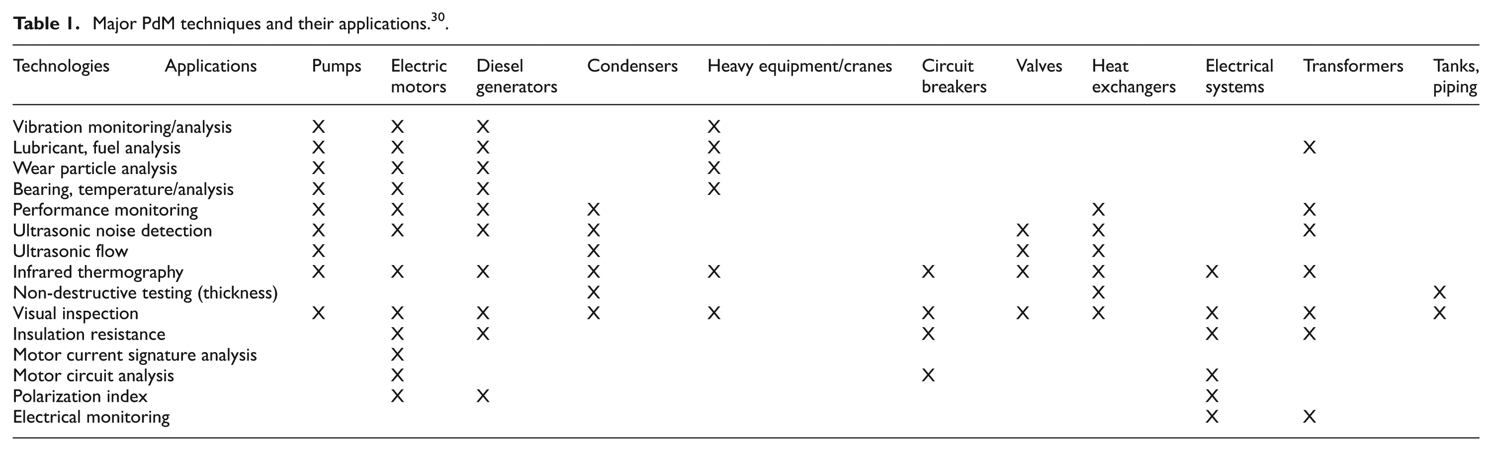
Choosing appropriate PdM techniques (Table 1 can be a useful guideline in making such a decision).
In selection of the first two above, the following can be useful guidelines although they were given for rotary machines in Tandon and Parey:
46
A technique/parameter that is sensitive to change in the machine condition should be chosen. A technique/parameter that is least influenced by operating condition changes and interference from other machines should be chosen.
Determining the location(s) of sensor(s).
Setting critical thresholds for each variable.
Determining inspection interval: Either continuously; Or at condition-based intervals; Or at regular intervals, which can be determined by expert opinion and/or manufacturer’s recommendation and/or past performance.
Choosing appropriate CMMS that manages the maintenance programme.
Major PdM techniques and their applications. 30
An example Gantt chart regarding setting a PMP, which shows the tasks involved along with their order and the required time for completion, can be found in a work conducted by Carnero Moya. 47
For successful implementation of PdM, the following points should be taken into consideration in general:
In most cases, combining PdM with TBM is the Choosing the right maintenance policy: best policy, 34 taking a position of being on the safe side.
There is not only one technique that is enough for all equipment/machinery in one facility. Especially, vibration analysis and oil analysis complement one another. Each PdM technique has been developed to pick up a certain sign of deterioration of a particular component. Monitoring a given component by more than one PdM technique delivers more reliable and comprehensive information about the component’s condition.
Data should be gathered when the system is still healthy as reference; that is, baseline data.
Gathering data about conditions of the system but not using the data should be avoided. Data should be turned into information, then into decision and then into action in the end.
It should be noted that measurements sometimes change as a result of operational changes, such as load, speed or temperature, rather than a deterioration in the system monitored. Consequently, the distinction is of paramount importance to avoid false alarms. For example, vibration taken at operation at 50% load may increase by as much as 400% with no change in the mechanical condition of the compressor. 48
For efficient management, the root cause of the breakdown should be addressed, not the symptoms only. For example, instead of merely replacing a damaged bearing (the symptom) in a gearbox, operating conditions, such as load or speed (the root causes), must be addressed.
Since no two plants can have the same maintenance requirements, adopting without adapting must be avoided.
Future directions for PdM
Developments in information, communication and computer technologies (ICT), especially on researches on sensor technologies, identification and tracking of entities and local data storage, signal processing and decision-making, have been supporting PdM, making it more powerful, applicable and affordable, and hence acceptable by all sorts of industries. In this section, research areas that support PdM works are summarized as follows:
E-maintenance. The term e-maintenance has been in use since early 2000, 49 and it is defined as ‘maintenance management concept whereby assets are monitored and managed over the Internet’. 50 E-maintenance is viewed as a PdM system that provides monitoring and predictive prognostic functions. 51 Lee et al. 52 state that ‘E-maintenance addresses the fundamental needs of predictive intelligence tools to monitor the degradation …’, linking e-maintenance to PdM.
Remote maintenance and management systems (RMMS). It is a similar and promising field, which makes it possible to execute PdM works especially in isolated or hazardous locations. Its earliest application can date back to 1995. 53 A subsequent application was proposed for aircraft maintenance. 54 Another example of such applications was developed for machine tools’ monitoring and maintenance. 55 In another example, a remote monitoring system was developed as a part of distributed control system (DCS) of a process plant. 56 Kwon et al. 58 reported robots being watched remotely to make a timely decision regarding the replacement while reducing the cost of unnecessary or premature maintenance, which is the very essence of PdM. It should be pointed out, however, that not all remote maintenance efforts can be considered as remote PdM work. For example, a remote sensing programmable automatic service time reminder (PAST-R), developed for bearings, alerts the user to perform the service as scheduled. 58 However, this work, although performed remotely, is not a PdM work since maintenance time is not determined by the actual condition of the bearing to be maintained.
However, as seen in all these examples, it is already possible to execute tasks of data collection, data processing and decision-making off-site, but actually intervening the system to restore it from a distance is another matter that requires further research. In addition, security and reliability concerns arising from transaction over the Internet are an important issue to be resolved in remote maintenance applications. 49
Tele-maintenance: a similar concept to remote maintenance is tele-maintenance. It enables maintenance crew to do the maintenance work themselves remotely and also in collaboration with other experts. The second way is referred to as cooperative work. 59 Tele-maintenance allows the diagnosis of installation and performs limited type of repairs from a remote location using ICT and sophisticated control and knowledge tools. 60
Internet of Things (IoT): although this rather recent concept has no uniform standard definition, 61 the following description helps to see how it can be utilized in PdM: ‘The IoT refers to the emerging trend of augmenting physical objects and devices with sensing, computing and communication capabilities, connecting them to form a network and making use of the collective effect of networked objects’. 62 Utilizing IoT in PdM work can offer new opportunities that can give rise to applications, such as remote maintenance. Such applications have already begun to emerge, for instance, a study that deals with maintenance requirements of a distant oil transfer station with the aid of IoT was reported. 63 Other utilizations of IoT for maintenance purpose were reported in the field of aviation equipment maintenance safety management61,64 And Espindola et al. 65 also reported IoT being used for PdM purposes. Many more examples that describe possibilities of IoT being used for maintenance purpose have been compiled by European Commission. 66
Radio-frequency identification (RFID): in addition to their usual usage in other areas, such as logistics, RFIDs are already being deployed in maintenance applications, 67 where the RFIDs not only serve the mere purposes of identification, localization and tracking but also store maintenance data related to past and future. The fact that they have embedded memory and support updating of storage information 68 lends them to be used as a part of a remote, updated and integrated PdM programme. Other examples of utilizing RFID in maintenance are reported in Lin et al. 69 and Atkins et al., 70 where RFIDs are used for laboratory equipment maintenance in both cases. Muller et al. 71 reported RFID applications in maintenance in various sectors, ranging from electric motor factory, paper factory, automotive industry and their supplier of robots to aluminium rolling mill. New generation RFIDs help optimizing maintenance work 72 and development of high-memory low-cost RFIDs will increase their utilization in PdM works.
Conclusion
Condition of no industrial system/installation/machinery/device/equipment/asset and so on remains the same in time and it is a complex task to maintain it in a state that it can function as intended since there are many factors governing the state of a system, namely, time and operational parameters, such as velocity, load, temperature, run time and presence of chemical agents. PdM is a maintenance policy that is based on the current condition of the system to be maintained. It is being practiced by the industry for many years, sometimes without being labelled as PdM, especially in early days. New PdM technologies in the market are strengthening PdM’s position in maintenance circles over traditional maintenance approaches, such as TBM, since PdM initiates maintenance work at the right time, neither too early nor too late, sometimes causing it to be named Just-in-Time Maintenance. 16 Initiating maintenance work only when needed not only minimizes risk of failure but also eliminates unnecessary maintenance, thus improving safety, reliability, quality, productivity, availability considerably and reducing cost. In addition, PdM practices alleviate environmental problems through reducing unnecessary energy consumption and maximizing life cycle of lubricants and spare parts. It should be noted that all these benefits of PdM are mostly attained without interrupting normal operation of the system. Combined with traditional maintenance policies, PdM can make all sorts of businesses more competitive and vital products and services, such as aviation, utilities and health services more reliable.
PdM has advanced in such a scale that there is now a new line of business that offers complete solutions, tailored for the customer company by means of integrating hardware and software requirements along with training services. In addition, new sensors introduced to the market are tempting maintenance managements to include them in their work, but for an efficient maintenance programme, it is necessary to focus not only on data acquisition but also on drawing timely and correct conclusions from the data and conduct the actual maintenance job accordingly. Additionally, recent advances in ICT have been lending themselves for new PdM’s applications. The following are some of the major emerging threads that seem to have the potential of rendering PdM more widespread and affordable:
E-maintenance or remote maintenance and management systems (RMMS) or tele-maintenance;
IoT used in maintenance;
RFID utilization in maintenance.
Footnotes
Declaration of Conflicting Interests
The author(s) declared no potential conflicts of interest with respect to the research, authorship and/or publication of this article.
Funding
The author(s) received no financial support for the research, authorship and/or publication of this article.