
Abstract
Remote Handling (RH) systems are now frequently used to conduct inspections and maintenance in hazardous environments. New particle accelerator facilities present unique logistic challenges due to high radiation levels, a hazardous environment and heavy loads. The Facility for Antiproton and Ion Research (FAIR) will deliver a beam of all ions up to uranium with intensities up to 1012 238U ions/s, which will cause high levels of radiation during operation so human access is limited. This paper contains a survey on RH logistics for existing High Intensity Beam (HIB) facilities to determine state of the art RH practices and to draw a conclusion based on the analysis. The second part of this paper presents a detailed study of beam losses, the radiation environment, RH logistic challenges and some proposed solutions for Super-FRS. This paper will also suggest a Systems Engineering (SE) approach for developing Super-FRS RH logistics.
Keywords
1. Introduction
The high energy and nuclear physics research communities are pushing the boundaries of known nuclides in order to understand nature at a basic level. The study of the fundamental questions about the universe in the field of nuclear structure and astrophysics has been enabled by modern fragment separator facilities. Fragment separator facilities are designed to deliver an exotic beam of rare nuclei via fragmentation and fission reactions based on a high-energy beam hitting a target. Advances in technology have enabled scientists to build high beam energy and power facilities for producing beams of short lived radioactive nuclei. The rare isotopes are radioactively unstable and they decay into more stable nuclei by emitting radiation. Figure 1 shows the nuclides chart as a function of their proton and neutron numbers. The stable nuclei found in the universe are shown in black and are stable with very long half-lives. The unstable and discovered nuclei are shown in orange. The green region of the chart shows nuclei that are predicted by the theory but unknown to mankind [1].

Chart of nuclide: stable, discovered and predicted nuclei. Presented as function of their Proton (Z) and Neutron (N) numbers [1]
The radioactive beam is now primary way to explore the uncharted region of the nuclei chart (Figure 1) and find answers to the question of the evolution of the universe [2]–[8]. The main aim of RIB facilities is to study nuclear physics to understand the nuclear matter properties and atomic nuclei to answer the fundamental questions of [7]. Such as, what is the significance of unstable nuclei in the process? To discover new forms of matter and to study the structure and behaviour of matter at extreme conditions, (namely) when a transition from nuclear to quark gluon matter occurs [3]? OECD global science forum's report on Rare Isotope Beam (RIB) facilities [7] shows that these facilities are providing the latest and most important research. The research has a direct impact on medical imaging, cancer treatment, environmental research, food processing, material sciences, accelerator technology, space technology and sciences, the fabrication of microchips, biology and clean energy technologies [7].
Within last decade major discoveries and progress have been reported by NuPECC [8] in the field of nuclear physics that have direct applications to society [7]. For the production of beams with high rates of secondary particles such as antiproton, neutrons, neutrinos and rare isotopes, very high intensity beams are required. The beam interacts with a target that causes the degradation of material properties and limits the lifetime of beamline equipment. The degraded targets, collimators and beam dumps also become activated due to the beam interaction and hence must be shielded to protect humans, which consequently requires remote maintenance.
Existing low energy exotic nuclei beam facilities are delivering beams with lower intensities, which are the basis for low levels of activation and radiation. The drive to push research boundaries and understand nature requires facilities with high beam power and energy. However, this development of new research facilities [5]- [49], which can deliver such powerful beams, will generate more activated parts. The handling and maintenance of the activated parts has to be done remotely and the facilities' design should incorporate the RH provisions.
This paper will compare the RH logistics solutions and issues at existing and future rare isotope beam facilities and explore the RH logistic scenario for Super-FRS at the Facility for Antiproton and Ion Research (FAIR).
2. RH maintenance survey of High Beam Intensities (HIB) existing facilities
This chapter will discuss the existing and future High Intensity Beam (HIB) facilities with activated targets and state of the art RH techniques used to handle the activated parts.
2.1 HIB facilities with proton beam
Table 1 shows a list of large accelerators with targets for high intensity beams (HIB). These HIB facilities accelerate proton beams that are used for the production of secondary particles such as antiprotons, neutrinos, muons, or serve as a pulsed neutron sources by spallation. Facilities for the production of muons and spallation neutrons require lower beam energy and the secondary particles are easier to shield compared to higher beam energy, which is needed for antiproton or directed neutrino beams.
Selected HIB facilities

Many of these HIB facilities use close shielding around the beamlines to avoid the spread of radiation close to the source, which reduces the overall volume required. To insert devices into the beam the vertical plug concept is used. Following a standard method of radiation shielding against fast neutrons, the inner part consists of iron as a material of higher density, whereas the outer part, which is of large volume, is made of cheaper concrete for neutron moderation and absorption. Still, much shielding can be saved by having the target in a tunnel below ground level, so that in addition soil can make up part of the shielding. In such an underground tunnel space for extended maintenance setups and additional close shielding with plugs is usually limited. In these facilities activated parts must at least be transported from the beamline to a maintenance region built as a hot cell or workcell detached from the beamline. In a scenario with enough space and cranes for heavy equipment the maintenance area can be separated completely from the in-beam position with either a shielded transport tunnel or a mobile shielding flask.
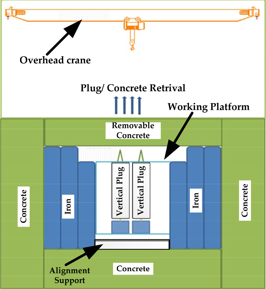
Sample closed tunnel drawing with vertical plugs.
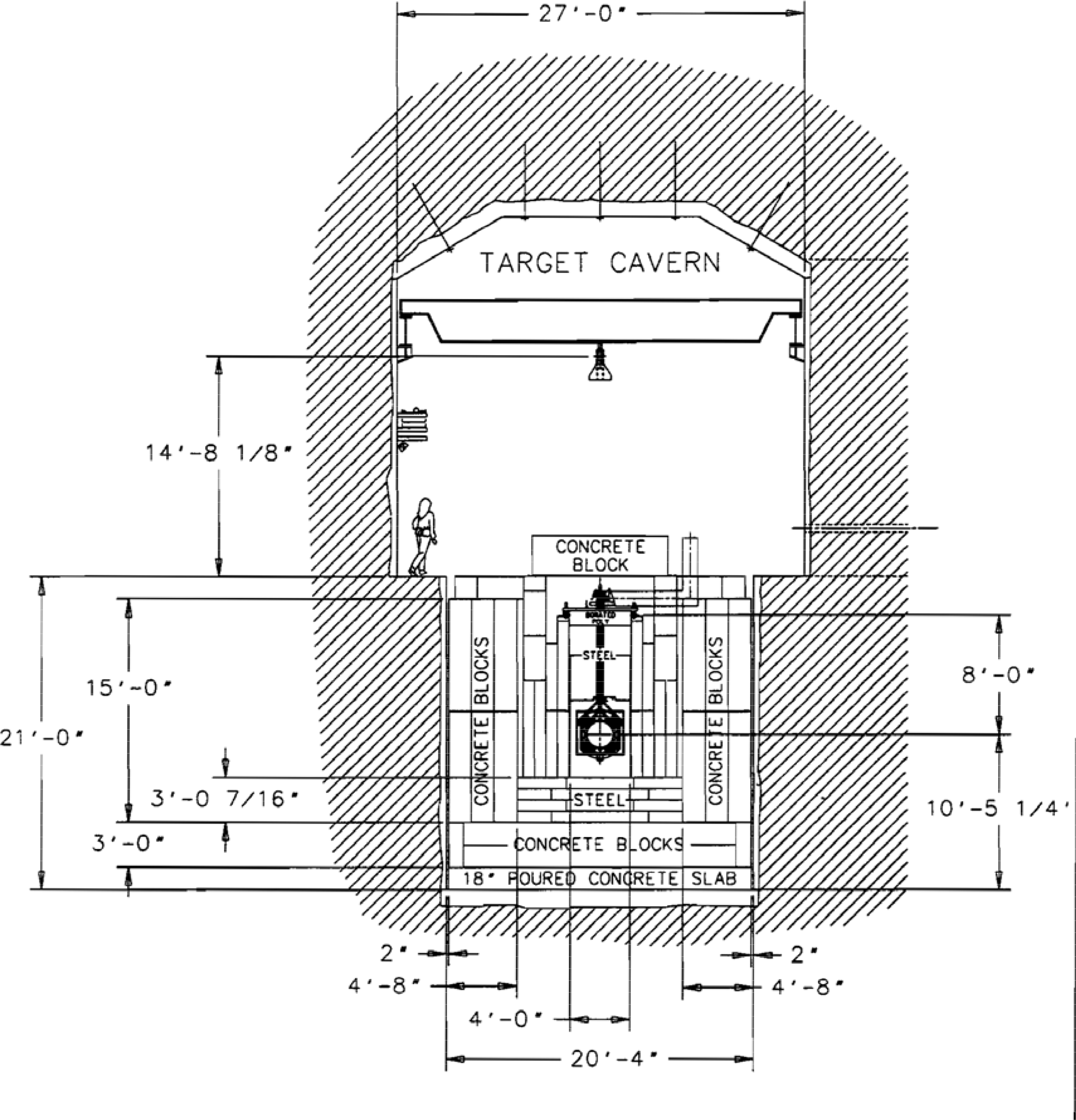
Fermi lab NuMI target area cross section [29]
Figure 2 shows the basic parts of a close shielding with plug inserts. The main purpose of the plug is to limit activation on the side opposite to the beam to a level where hands on maintenance becomes possible. At the same time radiation sensitive material such as vacuum seals is protected. This solution in principle offers well-protected access as there is always shielding between the main source of radiation and the operator and it limits the necessary motion to simple vertical movements. However, at the same time it increases the weight of the components drastically as they become directly connected to the heavy shielding blocks. Still it is the method of choice at the following places.
The analysis of antiproton target studies at the Fermilab and future FAIR [27] facility indicates high levels of radiation, for which iron and concrete shielding is required. The space is confined due to the shielding and high level of activation that requires maintenance by RH. At the FermiLab 120 GeV proton beam facility NuMI [26] (Figure 3), the neutrino target is mounted on a vertical plug in a closed tunnel heavily shielded with iron and concrete [29]. An overhead crane is used to remotely transfer the target from the beamline to the workcell area where basic maintenance is carried out. The T2K target and horns, at J-PARC are also mounted on plugs and are retrieved vertically using RH with a weight of 40 tons. Then the T2K target is shifted to a hot cell where RH maintenance is performed before it is stored [33].
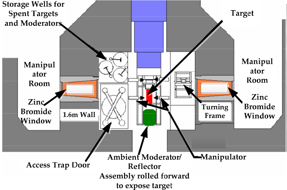
The PSI cyclotron delivers a proton beam of 2mA at 590MeV. The target E region (Figure 4) has heavy close shielding. Limited access is available at the top of the beamline components after the removal of concrete shielding. The beamline equipment mounted on plugs is pulled out vertically and transported to the hot cell region in shielding containers [24]. Similarly the SINQ target at PSI is retracted/installed and transported vertically from the target area to the hot cell where the target is dismantled or maintained remotely using master-slave-manipulators and power manipulators [43]. PSI has a well-established hot cell that performs maintenance operations on the activated equipment. Maintenance demands a downtime of weeks due the complex operation and heavy loads [24].
The muon target, magnets and pillow seals located on the 3GeV proton beamline in the MLF facility at J-PARC are also installed on vertical plugs. During maintenance, the target is also remotely installed and removed from the top onto the beamline using a shielding cask. The beam line is heavily shielded from the top and sides. The beamline inserts in the closed tunnel are accessible from the top once the shielding is removed and radiation levels are low [34].

PSI target region heavily shielded [24]
However, even larger target installations like large liquid target assemblies cannot be transported in a shielding container or mounted on an even larger shielding plug, they have to be maintained on site. The hot cells in these facilities are built on the top of the target region to conduct onsite remote maintenance. This is typical for spallation Neutron sources (SNS) where a high intensive pulsed proton beam is impinged on the target [35]. The SNS Oak Ridge facility uses an intense proton beam of 1 GeV to generate neutrons by spallation. The target at the SNS Oak Ridge facility uses liquid Mercury that requires RH for maintenance. The SNS facility target region is one large hot cell that uses master-slave manipulators and a telescopic servo manipulator to exchange, maintain, store and transport the activated parts (Figure 5). The target area is not closely shielded due to the energies and research at the facility [36], [38].
Similarly, the JSNS facility at the J-PARC facility uses a 3GeV proton beam on a liquid Hg target to generate neutrons. The target assembly is mounted on a moveable trolley that can be retracted and remotely removed into the hot cell and later transferred into storage cell [39], [41], [42]. The target is retrieved horizontally into the hot cell where it is removed and replaced with the help of an overhead power manipulator and a target exchange truck [39].

SNS Oak Ridge facility target (hot) cell cutaway [36]
ISIS target RH setup [41]
The ISIS facility at the Rutherford Appleton laboratory uses 800MeV and 160KW proton beam on a solid tantalum clad tungsten target [40]. The target is maintained by two master slave manipulators positioned opposite each other with dedicated windows (Figure 6). The cell also has a crane and cameras to provide assistance in remote manipulation. The spent target is stored close by and removed via an underground mechanism [41].
For HIB machines with very high beam energies of 100's of GeV, even up to 7TeV, close shielding becomes impractical and would even lead to an increased dose rate for maintenance. The reason for this is the much higher attenuation length for the secondary radiation and in addition a build-up of radiation where from one particle many more particles are created, which leads to an avalanche of radiation. In this case more material close to the beam would make activation even worse. The very long attenuation length can only be reached by distribution over a large area and far underground. The most extreme example is the he Large Hadron Collider (LHC). It collides two opposing proton beams up to energies of 7TeV. Over the whole circumference of 27km collimators are installed which require maintenance, as well as the dedicated beam dumps [44].
The CERN CNGS target also includes high energy protons (400GeV) from SPS that interact with an assembly of five graphite rods mounted on a revolving assembly encompassed by iron shielding [32]. Operational problems have made it evident that adequate shielding measures to protect electronics and personnel during operation [30] are required. The facility tunnel is underground and uses no shielding [31]. The target station can be remotely inspected but there is only space for a remotely controlled overhead crane and cameras [30]. The CNGS target is not coupled directly to a hot cell to maintain in.
2.2 HIB facilities with RIB targets
Rare isotope beams (RIB) are produced using two techniques (Figure 7): in-flight separation and isotope separations online (ISOL) [9][10].
In-flight separation means nuclei in a heavy ion beam are converted to other nuclides while passing a target. As the many different fragments are produced they need to be separated with the help of electromagnetic fields in a fragment separator. With the help of further interaction between degraders, the nuclides can even be separated by mass and charge independently. This method of operation means there are high levels of radiation due to the beam interaction with the target. Most of the beam is dumped in the separation process and towards the end of the separator the radiation level drops. Parts hit by the intense beam, like the dedicated beam catchers, become strongly activated. In the ISOL facilities nuclei in the target are converted by bombardment with a high intensity beam of mostly protons. The nuclei produced are then extracted from the target and collected in a low energy beam with the help of an ion source. Afterwards a low energy but high resolution mass separator is used to select the nuclides of interest. As energy is lower except for the target little activation is caused but due to the extraction from the target contamination poses a severe problem. Figure 7 illustrates the different production schemes.

Table 2 shows a list [10] of RIB facilities that use either in-flight or ISOL methods to generate the beam. In current facilities such as GSI [21] and ISOLDE [5] some RH techniques to retrieve and install the target area components are applied. At the target area and the first focal plane of the FRS (Figure 8) close to the vacuum chambers dose rates ranging from 200µSv/h up to 2mSv/h can be reached [4].
These two critical areas can be accessed in a controlled mode for limited periods of time after beam operation. For RH GSI uses two six-axis KUKA robots to conduct the remote maintenance/replacement of different parts such as collimators, target ladders, slits and in-beam detectors with the help of dedicated media panel connectors [4].

Projectile Fragment Separator FRS and the two robot positions for RH processes.
Selected RIB in-flight and ISOL facilities.

The ISOLDE Facility at CERN, which delivers proton beams up to 1GeV with 3.2×10¹³ ions/1.2 seconds, also uses two industrial robots for RH and storing the targets (Figure 9) [5]. The robot at ISOLDE has to conduct complex dexterity object manipulation to grip and remove the activated target from the beamline and perform transport manipulation to safely transfer and store the target in a temporary storage area.
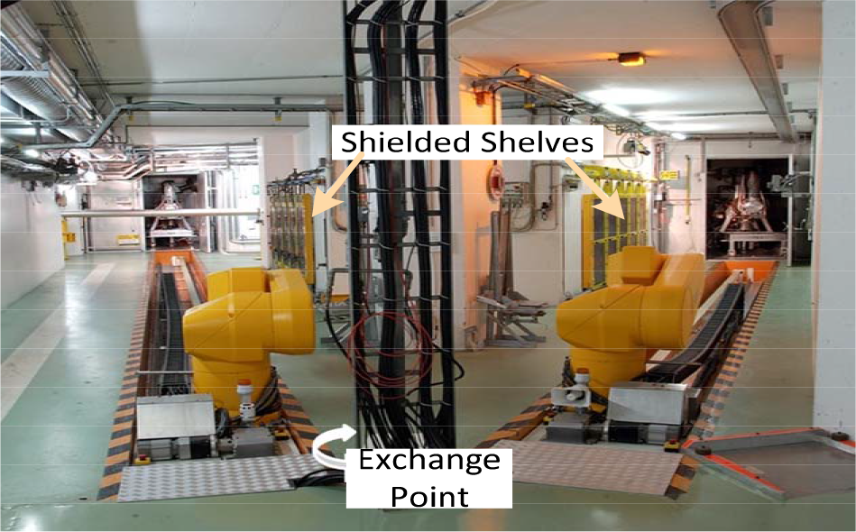
ISOLDE CERN target area RH setup [5]
Future facilities such as FRIB are adopting a close tunnel approach to maintain the activated parts. While the SPIRAL2 facility, which is an ISOL facility, is building a hot cell on top of the beamline. Both of these facilities have to perform maintenance by RH due to high levels of activation. These facilities also use iron-concrete shielding to provide protection against high levels of radiation. Hot cell development is also planned for both of the facilities to remotely maintain the activated equipment such as targets and beam dumps [18], [23].
2.3 HIB Survey Analysis
The HIB facilities analysis can be divided into following categories:
The first type of facility is developed with a closed tunnel design concept and vertical plug system (Figure 2) where the hot cell is located separately from the beamline. Such facilities require the remote transfer of beamline equipment during maintenance. Examples include PSI, JPARC MUSE, Fermilab NuMI and T2K at JPARC.
The second type of facility builds the hot cell on top of the target area (Figure 5, Figure 6). SNS, JSNS, ISIS, FRIB and SPIRAL 2 are examples. The hot cell is equipped with MSM and power manipulators to conduct maintenance on site.
The third type of facility uses very high-energy beams such as LHC and CNGS at CERN. These facilities are built with an underground open tunnel to provide natural shielding. The shielding of the beamline at such high energies is impractical from an RH maintenance point of view.
The fourth type of facility are developed with an open tunnel that uses localized shielding around the target area and the activated parts are replaced with industrial robots. Such facilities include the FRS and ISOLDE targets exchange systems.
3. Super-FRS beam losses and radiation environment
Based on the experience gained from the existing FRS facility, GSI is also responsible for the development of the Super-FRS facility shown in Figure 10. The new accelerators of FAIR provide primary beam intensities of up to 1012 ions/s of 238U at up to 1.5GeV/u [11]. In general the FAIR ion beams will have a factor of 100–1000 times higher intensity than currently available at GSI [21]. In this section we will provide a detailed analysis regarding the beam losses in the Super-FRS facility for 132Sn and 100Sn ion settings and an overview of the radiation environment in Super-FRS.
3.1 Beam Losses at Super-FRS
The Super-FRS facility is divided into a pre-separator, a hot cell and a main separator [11], [12]. The purpose of the separator is to select only nuclides of a certain rare species. This means that the initially high beam rate will be reduced more and more along the beamline (Figure 10). Consequently, the activation levels differ by orders of magnitude along the Super-FRS tunnel [49], [50]. A detailed Super-FRS layout can be seen in Figure 10 with respective maximal beam intensities.
The purpose of Super-FRS is to select certain species of mostly exotic nuclei out of the large intensity of different nuclides produced. This is done by the so called Bρ-δE-Bρ method [21] where in addition to the simple analysis by magnetic rigidity (Bρ) the ions are further separated by a second Bρ analysis after having passed a layer of matter (degrader) in which ions of different elements lose a different amount of energy (δE). Whereas the first step selects mainly ions of similar mass to charge ratio, the second step adds selectivity by atomic number. In Super-FRS this method is applied twice in the pre- and the main separator.

Super-FRS layout for the production, separation.
Since the main purpose is to select only a few ions out of up to 1012/s, the beam losses and where they will occur exactly can be predicted well. However, as there are many different settings for less and more rare isotopes, the intensities in the main separator can vary enormously. To illustrate the situation two examples were chosen: selection of 132Sn produced in a fission reaction from a 238U beam and 100Sn from projectile fragmentation of 124Xe (Figure 11). 132Sn and many other fission fragments with a similar mass and atomic number can be produced in high quantities and are difficult to separate due to the larger momentum spread of the fragments behind the target [46]. 100Sn and its neighbours on the chart of nuclides are produced much less and at higher energies like at Super-FRS they are also easier to separate.
In simulations with the Monte Carlo code MOCADI [47] for ion transport in beamlines including matter we collected the losses for all relevant nuclides produced as a function of position along the Super-FRS beamline (around 1000 different nuclides for 132Sn and 490 for 100Sn). As we are interested in estimating the level of activation of beamline components the number of ions only is not a good criterion, the energy of the ion and mass and atomic number are also important. Heavier ions contain more nuclides but ions of higher charge can be stopped faster. This was considered by comparing the number of emitted neutrons for each ion derived from a simplified scaling rule as described in Ref. [48]. So the number of ions lost shown in Figure 11 actually refers to 114Pd ions at 1300MeV/u an ion roughly in the middle of the mass and energy distributions of all the ions in the different sections of Super-FRS. This procedure also allows a loss number for inserts like the target or the degraders to be defined, through which the ions fly through without being lost. However, as the energy is reduced the amount of neutrons corresponds to the difference of neutrons emitted at the entrance energy minus the number of neutrons emitted at exit energy.
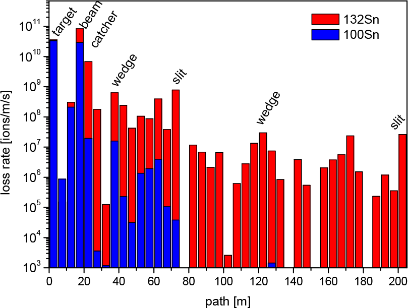
Number of ions lost along the path of the Super-FRS beamline per meter and second. For both cases, 132Sn and 100Sn settings, an initial energy of 1.5 GeV/u and an intensity of 3.3×10¹¹ ions (238U or 124Xe, respectively) was assumed. For clearer presentation the numbers were averaged over 5m wide bins. Key loss points are labelled.
As one can see, the main loss points are the target and the beam catchers but also later in the system local maxima occur, such as at the degraders or at the exit slits where a large part of the separation happens, some ions drop out even earlier before the slits, for example in the dipole regions.
Super-FRS has three branches [46] but here only the path towards the storage rings was considered as it sets the scenario where the highest beam intensities can pass through the whole separator. In the other branches beam tracking with detectors will be used, which is not possible at these high particle rates.
The difference between the two cases shown at the exit slit is also significant. So far it cannot be foreseen how often each case will be used during operation. However, it is clear that the high intensity case is only one out of many and will therefore not run the for whole operation time, but only a small fraction of it with correspondingly lower activation. Only in the pre-separator do we want high intensity on the target for all of the operation time.
3.2 Super-FRS Radiation Environment
In general the goal is to stay far below the annual dose limit of 20mSv per year for radiation workers in controlled areas. For free access the annual dose rate limit is translated into a limit of 0.5µSv/h [49], [50]. The highest activation will be in the target area (Figure 12) at the beginning of the Pre-separator. It starts with the beam line inserts, i.e., the Super-FRS production target and ends with three beam catcher chambers, as these components will be exposed directly to the intensive primary beam [49]. After the beam has interacted with the target a series of graphite and iron beam catchers will be used to stop the primary beam at locations where the primary beam and selected fragments are separated. The pre-separator will be exposed to a large amount of radiation and subsequently will be activated even after the cooling period.
Figure 12 shows that according to FLUKA [49] simulations radiation levels inside the shielding are well above 0.5µSv/h during beam operation. The beam catchers are subjected to high levels of activation since up to 85% of the beam is absorbed by it. The target and the beam catchers will be subjected to radiation damage and will require replacement multiple times during the Super-FRS operation.

Dose rate calculation with FLUKA during beam operation [49].
Figure 13 represents the target region activation levels from the FLUKA simulation. According to the simulations, the residual dose for the beam catchers is in the Sv/h region even after 120 days of cooling. The working platform has a radiation level of 10µSv/h and can be accessed by humans to make and break connections. The human presence is limited and controlled on the top of the working platform [49], [50].
The beamline inserts exposed directly to the primary beam are exposed to high temperature and pressure and due to radiation damage these parts must be partially replaced. The work on the systems to hold, move and exchange the target and the beam catchers can only be done by remote handling inside a hot cell [11].

Activation levels from a FLUKA simulation near the beamline and on the working platform after an irradiation period as indicated on top.

FLUKA simulation for beam catchers inside the hot cell with 1m thick walls after 120days of cooling [53].
The beam catcher will be the most activated part to be worked on in the hot cell. The residual dose rate calculation for shielding of gammas from the beam catcher shows that a cell with a 1m thick wall is suitable for remote handling. The remote maintenance equipment is described in [53], [54].
Super-FRS also consists of a 130m long main separator made up of four dipole stages with focusing elements in front and behind the dipole magnets. The main separator is also divided into three branches: a Low-Energy Branch (LEB), a High-Energy Branch (HEB) and a Ring Branch (RB), as shown in Figure 10 [17].
The beam intensity and losses are reduced (Figure 10) along the focal planes in the main separator and radiation levels are much lower compared with the pre-separator. The exposure of focal planes MF1 and MF2 to the high intensity beam also causes higher levels of activation,
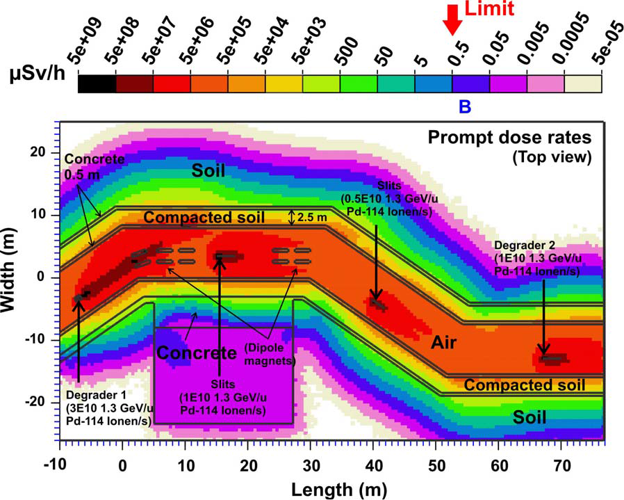
Main separator radiation prompt dose rates [51].
which can be seen Figure 15 [51]. The residual dose in the main separator is also subsequently lower due to lower levels of activation compared with the pre-separator. The radiation analysis indicates that the main separator will experience conditions similar to the existing FRS with the second half of the pre-separator being similar to the current FRS target region. The experiences and lessons learned from FRS can be implemented on Super-FRS for the RH logistics concept.
4. Super-FRS equipment remote handling/maintenance logistics challenges and requirements
4.1 Pre-separator region
The pre-separator consists of the Super-FRS target, beam diagnostics and the beam catchers (Figure 10). These activated and possibly damaged parts require remote maintenance. The beamline equipment has to be positioned inside the vacuum chamber for the beam.
Here the concept of close shielding with plug inserts will be employed as listed in Point 1 in Section 2.3. The neutrons from beam losses can be shielded with a combination of 2m of iron plus 5m of concrete to allow uncontrolled access on the outside. Also on the top 2m of iron reduces the activation level far enough to be able to do hands-on maintenance on systems on top of the plug inserts. Figure 16 shows an overview of this area. As this section is almost 30m long with many positions for maintenance a direct connection to a hot cell was not chosen but a transport flask, see Figure 17, can be used to move the individual plugs to one common hot cell. In this case, hand's on maintenance is only possible on the topside of the iron plug. However, this also increases the size and weight of the beam line components. The beam line inserts will be mounted on similar shaped iron plugs but the weights, sizes and dimensions of the iron plugs will differ based on equipment mounted on the plug, the position of the plug and space available for the plug in the vacuum chambers. The plugs are weighed in tons and the maximum weight estimated is 7.5 tons for one of the beam catcher plugs. Consequently a large shielding flask with up to 40cm of iron shielding is required
The challenges in the design and development of the shielding flaks are:
- The shielding flask must adhere to the SAFETY STANDARDS of the Nuclear Safety Standards Commission (KTA) [52].
- The shielding flask must be able to safely transfer the different types of plugs with beamline inserts from the pre-separator region to the hot cell region.
- Shielding flask systems should be back drivable in case of failure. The design shall be designed according to reliability, availability, maintainability and safety (RAMS) standards.
- A common interface is required between the shielding flask, pre-separator vacuum chambers and the hot cell.
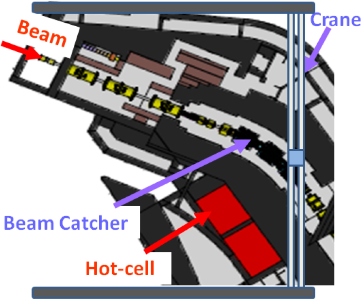
Pre-separator target hall floor plan and logistics environment.
4.2 Hot-cell region
The hot cell will be used to maintain, repair, replace and store the activated beamline inserts. The hot cell facility has to service activated equipment from two sections of the FAIR facility:
Super-FRS beamline inserts
Antiproton target and magnetic horn
The transfer from Super-FRS to the hot cell will be within the same building under one roof using the shielding flask (Figure 17). The antiproton target and magnetic horn have to be transported in a separate flask using a special mobile vehicle that can move heavy loads up to 20 tons from one building to another. The containment vessel is used for the transfer of activated parts; hence the containment flask has to be approved by KTA [52].
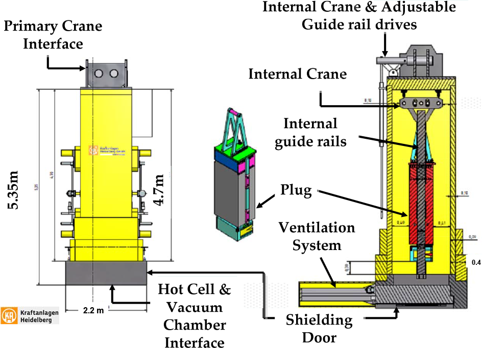
Shielding flask with expected subsystems for transporting plugs of up to 7.5 tons.
The hot cell operations will require two pairs of MSM and a power manipulator with a crane to provide reachability for RH logistics. The hot cell logistics also require custom designed tools, fixtures and stands. The work comprises power tools (cutting, drilling, torque wrenches, holding/handling stands) to allow RH activities. The RH logistics also require common interfaces for the RH equipment to be considered to avoid interface duplication. A waste storage area is also designed alongside the hot cell to store waste. The waste is first stored in a storage cell with limited capacity, then after additional cooling time it is stored in dedicated containers for many waste barrels and transported to a separate FAIR storage building.
4.3 Main separator
The last part of the pre-separator and the first part of the main separator (PF2-PF4-MF1-MF2) (Figure 10) includes beamline equipment that can weigh up to 500kg. They require both maintenance and inspection to keep the beamline operational with the use of minimum resources. Beamline remote inspection and maintenance can be performed with mobile industrial robots and beamline equipment that is designed for remote handling. Due to the radiation levels during beam operation in the main separator (Figure 15) a mobile platform will allow robots to get out of the tunnel when the beam is turned on and avoid radiation damage.
We have the following requirements for the open separator tunnel:

The robot will also require specific custom designed tools to handle the beamline equipment. The mobile robot platform will require alignment and charging systems that will enable the mobile platform to accomplish the required remote handling tasks. The LEB, HEB and RB areas will have experimental setups and can be openly accessed once the beam is switched off, with no RH maintenance setup required.
5. Systematic approach for Super-FRS logistic Concept Development
Super-FRS is a complex machine that comprises multiple complex systems. The SE approach is necessary for developing Super-FRS RH logistics because 70% of the cost for complex systems is fixed [55] (Figure 18) at the concept design stage; hence it is of utmost importance to develop a reliable system from the initial stage. In order to ensure the Reliability, Availability, Maintainability, Safety (RAMS) and the costs concerned, a Model based Systems Engineering (MBSE) will be adopted.

Estimated cost distribution against product life cycle time [55]
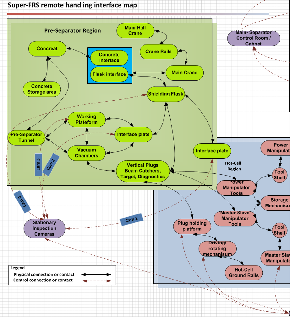
Super-FRS RH systems interface map part 1

Super-FRS RH systems interface map part 2
The MBSE approach is an effective methodology for developing a complex product from the start by defining the correct requirements. The equipment designed for Super-FRS is unique in nature and the RH logistics are undefined. The Super-FRS RH systems logistics division is shown in

Proposed SE approach for developing Super-FRS logistics
An MBSE approach adopted for developing the RH logistics is shown in
6. Discussion
The RH of the activated beamline components is now a necessity amid HIB facilities since new facilities are designed for more intensive and powerful beams. Currently the existing HIB facilities across the globe such as J-PARC, Fermilab, SNS, PSI, ISOLDE and FRS use RH to maintain the equipment. The designs of the future RIB facilities such as Super-FRS, FRIB and SPIRAL 2 are becoming more complex and they have to consider RH from the initial stages. Before, facilities were often gradually upgraded but with the expected strong activation gradual upgrades are very difficult and not an economic option. All infrastructures also have to be laid out for RH at the conceptual design stage. These design constraints directly highlight the RAMS and cost issue (regarding the designs and downtime due to maintenance) from the start.
The HIB facilities survey also indicates that RH activities have two main aspects: 1) transportation manipulation [24], [29], [33] 2) dexterity manipulation [5], [24], [41]. In HIB facilities a combination of dexterity and transportation manipulation is required depending on the facility's design. In some cases (PSI and J-PARC myon target) heavy equipment is transported to a separate hot cell for complex dexterity object manipulation using MSM and power manipulators. In other cases, like ISOLDE and GSI-FRS, dexterity object manipulation is carried out to disconnect the activated part before transport manipulation. In the later case normally a robot with special tools is an optimal solution.
Based on the survey study the RH maintenance for activated parts can be divided into two categories: scheduled and unscheduled maintenance. Each of the fore mentioned categories can be further subdivided into three sections: long term maintenance (LTM), mid-term maintenance (MTM) and short-term maintenance (STM) depending on the time and resource constraints. For the future facility Super-FRS, remote maintenance (scheduled or unscheduled) can be divided using the concept of LTM, MTM and STM as listed below:
The time required for equipment such as beamline magnets and the vacuum chamber is estimated in months, they will not be replaced unless there is a problem with the equipment. Maintenance of the fore mentioned equipment will also require numerous resources; hence such equipment can be assigned to the LTM category. The down time of beamline is expected to be in months and will require a long-term shutdown of the Super-FRS facility. For most of these devices no spare parts will be in stock.
Target area equipment remote maintenance such as beamline plugs in the Super-FRS pre-separator region will cause beamline downtime for weeks rather than months. The resources along with the time required are less compared to LTM and hence this equipment can be assigned to the MTM category. Spare parts for the consumables are available.
The Super-FRS equipment maintenance located in the open tunnel of the main separator and experimental areas can be performed in days or for smaller repairs also in hours. Hence this can be assigned to the STM category
Table 3 summarizes possible LTM, MTM and STM examples within HIB facilities. Remote maintenance scheduling, planning and execution are complex logistics tasks that require further comprehensive research.
HIB facilities LTM, MTM and STM categories and examples

Energetic particles interact with matter depending on the mass, energy, charge and nature of the target material. The radiation sensitivity of the electronic components normally depends on multiple factors such as “dose rates, time of exposure, biasing conditions during and after radiation and temperature” [57]. The RH tasks are carried out once the beam is shut down and after a cool down period. The residual dose at this stage is only caused by the activated parts and hence is much lower compared with the situation where the beam is on. In the case of Super-FRS, the ratio between the prompt dose and the dose by activation after years of full usage lies between a factor 105 to 106 depending on the cool down time.
Dose rates can be predicted but due to the complexity of electronic devices and to some extent different operating scenarios, it is hard to predict the lifetime for electronic devices exactly in different radiation environments at HIB facilities. Hereafter radiation hardness assurance accelerated testing is performed on electronics in a simulated environment, using test procedures documented in MIL-STD-883 C, Method 1019.4 [58] in the USA and ESA/SCC basic specification no. 22900, Draft C [59] in Europe. The radiation hardness assurance testing is conducted to reduce the number of devices in a radiation environment to a minimum, to carry out failure detection and to improve reliability and redundancy [57]. The RH system profoundly depends on electronic circuitry and visual monitoring that will be exposed to radiation caused by activated parts. In order to prevent the RH equipment electronics from failing, the first step is to use radiation hardened electronics, the second step is to minimize the number of electronics directly exposed to radiation and the third step is to protect electronics from radiation if on board the equipment during the maintenance process.
In the current FRS target area the cameras installed permanently are not radiation hard. Hence, the camera system (CCD and control unit) was damaged completely in about half a year because it was exposed to a strong neutron flux when the beam was on. Therefore, these systems required replacement. The controller box for the KUKA robot is not installed on the robot in the FRS target area but behind concrete shielding. Even so, the actuators on the joints may be affected by radiation of even higher doses. Most industrial robot manufacturers, such as KUKA and FANUC, do not provide warranties for robotic equipment and electronics used in an ionizing radiation environment. As a safe limit, even for very sensitive semiconductor parts, the data indicate a dose of up to 1Gy, which can be received without failure. [57].
Due to the Super-FRS high beam intensities the pre-separator has to be shielded with iron and concrete that in consequence limits access and encompasses reliance on RH maintenance. Some sections of the main separator are also subjected to high levels of radiation and remote maintenance using industrial robots. The RH maintenance will also involve hot cell activities to maintain the equipment. All in all Super-FRS requires state of the art RH systems with effective logistics to maintain fluent operational stability. The implementation of the SE approach will enable Super-FRS to develop a RH maintenance system and logistics that will consider the RAMS issues, cost concerns due to design and downtime of the facility and utilize the existing/conceptual state of the art engineering design for Super-FRS RH logistics.
Future work includes developing RH logistics for Super-FRS and the implementation of an SE approach for Super-FRS. The issue of organizing RH maintenance planning and scheduling is of critical importance and needs to be addressed in the SE approach. This approach will include systems for defining clear specific requirements for logistic scenarios, concept development, simulation of the concepts and finalizing the concepts for RH logistics and equipment. One of the aims of this project will be to contribute to the “Open SE” project imitated by the PURESAFE network [60].
7. Conclusion
This paper conducts a detailed survey of RH maintenance systems currently operational at different HIB facilities with a focus on the future Super-FRS facility RH logistics needs. The survey concludes a unique analysis and discussion of RH issues in Section 6. This paper signifies that RH systems are now considered an integral part of the current HIB facilities maintenance and numerous future HIB facilities are adopting RH systems. The gradual RH maintenance improvement conducted in cases of GSI, ISOLDE and Fermilab will be costly and difficult for future HIB facilities, due to the changes in the facilities' RH maintenance system design and logistics at a later stage. Hence, the RH in future complex HIB facilities must be planned using a SE approach. The RH maintenance systems adopted by HIB facilities are typically dictated by the target area, beam energies, type of beam particle and intensities and beamline design. Hence the RH maintenance systems implemented vary in design. HIB facilities have no unified standards concerning radiation hardened electronic equipment so that field needs to be explored in more detail. Currently the ESA and DOD standards can be used to ensure electronic equipment safety in radiation environment.
This paper also presents key requirements and scenarios concerning the Super-FRS facility RH logistics. Super-FRS will provide one of the most intensive beams of rare isotopes for experimental and nuclear physics. Due to the target and beam catchers' radioactivity and activation, the facility will require remote maintenance capabilities. The main separator at Super-FRS is less activated compared to the target area, but it will also require remote maintenance solutions of its own. Due the different conditions in between the two Super-FRS regions, two different RH solutions will be implemented for remote maintenance. Therefore, to tackle the complexity of the Super-FRS RH system the RH logistics concept will be developed alongside the RH equipment design using an SE approach. The RH logistics developed with the SE approach will ensure robust interfaces and interaction between complex Super-FRS RH systems components thanks to the smooth transition from the requirement stage up to the design validation and implementation stage.
Footnotes
16. Acknowledgments
The authors express their sincere appreciation and thanks to the EU Marie Curie PURESAFE Initial Training Network (project number 264336) for funding and support and also express sincere gratitude to other GSI colleagues involved in the work on FRS and Super-FRS.