
Abstract
Many successful designs of compliant actuators have been recently proposed. However, the challenge of providing passive and active motion in one actuator has remained. In this paper, a novel mechanism for changing the stiffness of the series elastic actuator over a wide range is presented. An accurate force source is provided by introducing the force control using velocity control of the DC motor. Performance and behaviour of the system and controller is investigated through simulation.
Introduction
In recent years, there has been great interest generated in the promising field of environmental-interaction robotic systems. environmental-interaction robotic systems involve the close interaction between robotic systems and the environment, including direct contact and collision between the robot and the environment. So by interacting with the environment, performance specifications such as bandwidth, maximum force and torque capability, efficiency, and reachable workspace, do not fully cover the range of requirements which defined for robotic systems. For example, robotic systems interacting with human must consider the requirements of safety (Zinn, M., Roth. B., Khatib, O. & Salisbury, J. K., 2004). Also some robots must work in the environments with impulsive forces, some of them are designed carrying the fragile objects. Part of the robotic systems are demanding the passive motions like legged robots mimicking human or animals motion (Pratt, G. A., 2002), and prosthetics (Herr, H., Wilkenfeld, A., 2003), (Blaya, J., Herr, H., 2004). In addition several robotic applications include haptic and wrist devices in medical or surgical robotics, exoskeleton to amplify human power. The main characteristic behind the above robotic systems is the close interaction between robots and human being or unstructured environments. Thus in addition to different type of environmental characteristics the robot should perform different tasks with different executed force and frequency. The question arises as to whether it is possible to successfully integrate the mentioned competing requirements and performance in a single system. Part of the solution is brought in with the use of proximities sensors or monitoring software preventing the collision or performing the force by impedance control methods. However, most robust systems are subject to unpredictable behaviour as a result of electrical, sensor, or software faults. So the next criterion is to develop a mechanical design approach for dealing with the above problem of achieving the best performance, under the condition that the negative affects of interaction between the robot and the environment is minimized.
Compliant covering on the robot is one of the conventional methods to reduce the high frequency collisional effects, which is a reasonable solution for dissipating the bulk of impact load energy when the effective impedance can be approximated as the link's impedance. However, at low frequencies, the effective impedance at the link can be approximated as the sum of the link's and reflected actuator's inertia that is much larger than the link's inertia for many robotic systems. Clearly, adding large amounts of compliant covering is impractical. So another approach to achieving the inherent impact resistive and safe robot is provided by a mechanically compliant robotic system design (Pratt, W. G. A. & Williamson, M. M., 1995), (Williamson, M. M., 1995). So by this trend the actuator's rotor inertia is dynamically decoupled from the links whenever impact occurs. Naturally, putting the compliancy in the transmission negatively affects performance in terms of increasing the oscillation and settling time. On the other hand the passive elastic transmission demands for optimization procedure to choose the best stiffness constant of the actuator's coupling or transmission.
Various amounts of transmission compliancy are required to keep the performance of the robot high in several desired tasks whenever interacting with the environment. Also providing very low mechanical compliance design is critical in several environmental-interaction robotic systems, i.e. in walking and mimicking robots gives the benefits of efficiency and passive motion while destroying the performance criteria. So, recently, new approach of an innovative electromechanical design providing the variable stiffness transmission was highly recommended by the researchers (Bicci, A. & Toneitti, G. 2004) and (Hurst, J. W. et. al., 2004). Consequently, in this paper we developed the actuation approach so called by
From the actuator control point of view, changes in the stiffness of the actuator causes the mechanical gain of the closed loop system to change. In addition there are other nonidealities in the system, such as stiction and amplifier saturation. To overcome some of these difficulties in controlling the torque (or force) of the actuator, we have proposed the velocity control of the DC motor instead of common method of controlling the current. Since the velocity control is very accurate and robust to stiction, the performance of the actuator will be improved consequently. The other reason of employing the velocity control is coming from the fact that the saturation depends on the power of the DC motor and amplifier. The power also relies on the torque and velocity of the DC motor. Thus, adjusting the commanded velocity in the torque control loop could prevent the saturation, indirectly. The control development of the actuator to track the commanded torque without considering the tuning of the stiffness is explained in this report. Finally performance of the actuator is examined by applying some test conditions on the actuator.
Related Works
Many researchers have studied compliant actuators or the effects of flexible links on robots control (Hanafusa, H., & Asada, H., 1977), (Mason, M., 1982), (Cannon Jr, R. H., & Schmitz, E., 1984), (Spong, M. W., 1987), (Sugano, S., Tsuto, S. & Kato, I., 1992), (Vischer, D. & Khatib, O., 1995). Some research has been done on direct drive actuation (Asada, H. & Youcef-Toumi, K., 1987) to increase the perfomance of force controllers. Taking advantage of compliancy for sensing the force on teleoperated systems was studied in (Kulishov, V. S. & Lakota, N. A., 1988). The deflection of actuators output and motor position were measured and used to enhance the stability of the force control method (Howard, R. D., 1990). By direct measurement of spring deflection which is in series with the actuators transmission, Pratt and Williamson (Pratt, W. G. A. & Williamson, M. M., 1995), (Williamson, M. M., 1995) introduced the
Joint Torque Controlled Actuation
Joint torque control systems are combined of an actuator and transmission with integrated torque sensors to achieve the desired performance levels. Joint torque control can successfully reduce the nonlinearities and friction inherent in the actuator-transmission systems generally in limited joint actuation bandwidth (Vischer D. & Khatib, O., 1995), (Hirzinger, G., etall, 2001). The implementation of the joint torque control allows for near zero low-frequency impedance, but it is ineffective at higher frequencies. Thus, the magnitude of impact load, which is determined by the high frequency impedance of the contacting surfaces, is not attenuated. While the joint torque control has been successful in improving the force and impedance control of robotic manipulators, their fundamental open-loop characteristics make them difficult to use in environmental-interaction robotic system.
Series Elastic Actuation
Series Elastic Actuators (Robinson., D. W. etall., 1999) have elastic element intentionally placed in series between the actuator and load. Deflection of the elastic element is measured to provide an accurate estimate of force. A linear feedback controller is implemented to regulate the output force by controlling the current of the DC motor as shown in Fig. 1. The elastic element limits the high frequency impedance of the actuator to the stiffness of the elastic coupling and provides low output impedance across the frequency spectrum. As a result of the low stiffness compliance, the open-loop gain is very low which allows the use of a simple, high-gain PD controller. The resulting system is stable and possesses low impedance over a wide frequency range, but an open loop characteristic of the SEA represents a fundamental physical limitation of the actuator caused by velocity and torque saturation of the DC motor. By choosing low stiffness elastic element in series elastic actuation, while keeping the impedance of the system low; the bandwidth of the system remains low. So stiffness tuning by each special application is one of the major considerations. Also coulomb friction and stiction are dramatically affected by the putting elastic element into the actuator that could not fully compensated by current control of the DC motor. The other limitation of SEA is that the passive motion of the external load can not be provided by SEA because of limitation in decreasing the stiffness of the elastic element.

General Schematic of the SEA actuator.
Distributed Macro-Mini actuation approach (DM2), was developed to overcome the safety limitations of joint torque control and the performance limitations of series elastic actuation on the manipulator to maintain the performance (Zinn. M. etall, 2004). The DM2 have a pair of parallel actuators that installed in different locations on the manipulator as shown in Fig. 2. For the high frequency actuation, very low impedance is achieved by using a small torque motor with low inertia connected to the manipulator through a low friction, low reduction cable transmission. For the low frequency actuation, low impedance is achieved by using a series elastic actuator. The SEA actuator is located at the base of the manipulator that significantly reduces the weight and inertia of the manipulator. The high frequency actuators are located at the manipulator joints and connected through a stiff, low friction transmission, providing the high frequency torque components that the low frequency base actuators cannot. This actuation approach also have some limitations such as: applications involving a number of different control modes i.e., free-space motion with contact transitions, applications requiring a low-impedance torque source i.e., haptics or tele-robotic master devices and applications involving a number of different tasks with wide range of impedance requirements, such as prosthetics knee or ankle.

General Schematic of the DM2 actuator
By considering the developmental limitations of each method of compliant actuation for the environmental-interaction robotic system application, a new actuation approach is necessary for satisfying the limitations of each method. So the rest of this paper explains the design of a new actuator for satisfying the part of limitations of the current methods.
In this paper we propose a new actuation approach, referred to as the Adjustable Compliant Series Elastic Actuator (ACSEA), that has been developed for environmental-interaction based robotic application. As the name implies, the ACSEA approach employs several parts including batteries, power amplifier, Actuation, transmission, controller and

General Schematic of the actuator elements.
Different methods of actuation have been employed for controlling of robots. Hydraulic actuators have limitations in terms of the required weight for instruments, oil leakage, friction and stiction, but have the benefits of high power-to-weight ratio and large bandwidth. Pneumatic actuators are inherently springy and compliant but have some difficulties in control and mobile applications and they have loss of energy. Electrical actuators can be precisely controlled with the additional benefits of safety, high power-to-weight ratio (using high ratio transmission), and mobility. For these reasons, the electrical actuation is chosen in our current design.
Transmission
Using a high-gear ratio transmission, servo motors provide high power-to-weight ratio at the expense of lower efficiency caused by gearbox deficiencies. Based on the requirements of each application, such as available space and mechanical configuration of the robot, different types of gearboxes can be used including: (1) cable gearboxes which produce no backlash, are light-weight, have low inertia and more than one degrees of freedom; (2) ball screw gearboxes which provide low friction, high gear ratio, linear motion and potentially very low or no backlash; (3) spur gearboxes are inexpensive, their output shaft is parallel to the input shaft but produce backlash and have high inertia; and finally (4) any combination of represented gearboxes or other types of gearboxes. The ball screw is chosen for transmission part of this work because of the higher efficiency.
Automated Adjustable Stiffness Coupling (AASC)
The AASC is installed between the output shaft of the DC motor's gearbox and the load, so the effective inertia of the load is isolated from DC motor by AASC. The main role of the ACSEA actuation approach is to provide the desired torque in a wide range of mechanical stiffness for the high frequency bandwidth. The effectiveness of ACSEA approach can be seen clearly when one considers that most robotics tasks involve position or force control which are dominated by low frequency trajectory tracking respectively low frequency desired torques. Also the advantage of adjusting the mechanical stiffness obviously increases the efficiency of the locomotion in walking machines while storing and releasing the energy is possible in different speed and step sizes. In addition energy will be saved during the passive motion by preventing the dissipation of energy in the amplifiers, DC motors and transmission. While the performance of the actuator is maintained by the maximum power and torque of the DC motor, the overall stiffness of the AASC adds the important factor in performance limitations such as flexible modes and low frequency bandwidth.
Perhaps the most challenging element of ACSEA is the Automated Adjustable Stiffness Coupling that is illustrated in Fig. 4. Two pressure springs are intentionally inserted between the two concentric input and output links of the actuator. Position of the springs described by d can be changed. In this case, the internal torque between the input and output links about the center of rotation O is calculated from:

Where d is the distance between the spring position and the center of rotation, θ is the angular displacement between the input and output links, and x is the spring deflections and KSpring is the stiffness of each spring.
The stiffness of the coupling could be determined from:
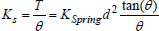
If the displacement of the spring to the center of rotation changes from d1 to d2, the coupling stiffness will be modified from KS1 to KS2 according to the following equation:


Schematic of the adjustable coupling.
For example, if d with an initial value of d1 = 20mm changes to the final value of d2 = 1mm, stiffness of the coupling decreases by 400 times. This capability of changing the stiffness in a wide range is desirable as will be discussed later.
From detail design point of view the coupling comprises of an input link, an output link, two springs, and spring positioning mechanism (Fig. 5). As shown in Fig. 5. two pressure springs are located inside the spring guide element. The spring guide element is linearly positioned by the nonbackdrivable ball screw and nut which is connected to the input shaft. Ball screw is connected to a brushless DC motor which in turn is attached to the input shaft. Position of the nut inside the ball screw is determined by the encoder installed in brushless DC motor. A guide shaft is fixed on the output link. Linear motion of the spring on ball screw is guided by a shaft bearing which slides over the guide shaft. Guide bearing is jointed to the spring housing and has sliding motion inside the slot deployed on spring housing. Consequently, with a relative torque on links, the angular motion between the links is converted to the linear motion of the springs. A potentiometer is used between the input and output links to measure the relative angular displacement of the links and finally extract the torque magnitude. The cross section of coupling is shown in Fig. 5.
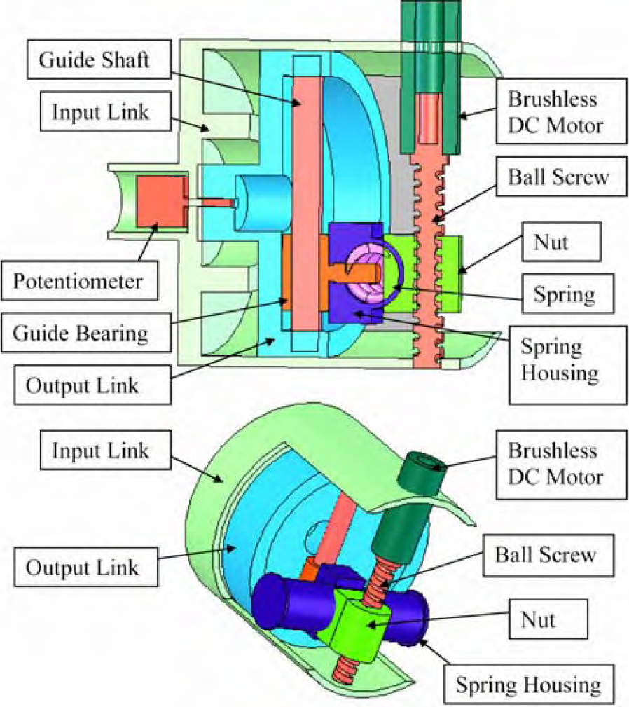
3D model of variable stiffness coupling.
Dynamics of the actuator is the next important issue in actuator design. Dynamics of the motor includes the motor inertia and viscous damping. Load is considered as inertia and damping which reflects on motor dynamics via the spring and the gearbox. Series elasticity with load has resonance effects which are influential through variation of spring stiffness and load mobility. So the nonidealities coming from the mechanical design such as stiction, flexible modes and bandwidth limitations should be maintained with the controller and hardware development. The actuator dynamics and control are explained in detail in the following section.
Possibly one of the most challenging aspects of the ACSEA implementation is the development of a control approach which maintains the performance characteristics of the ACSEA actuator while dealing with the unique control challenges associated with the change of stiffness of the coupling in a wide range. The adjustable stiffness characteristic of the actuators provides an additional flexibility to the system which can be used in optimizing performance of the system while minimizing actuation effort. For example, in the case of passive desired motion, we can use very low stiffness value let the system move passively or set the stiffness to obtain optimum energy storage. Fig. 6 describes the schematic of the control structure for the robotic system. For given motion specifications, the task management computes the desired torque and the stiffness value to the actuator as shown in Fig. 6. Based on such a torque request and torque error, the torque controller block computes the set value for the commanded velocity of the DC motor. The velocity controller block would only take care of closing the fast inner loop to ensure that the actuator follows desired velocity value. On the other hand different stiffness of the coupling is commanded by the task management block. Although controlling the stiffness to the desired values in AASC makes some difficulties but in this report we considered that the AASC could perfectly follow the commanded stiffness. In particular, we leave this problem to be solved in future works and mainly talking about the torque control method.

Schematic of the control structure.
Adding to special mechanical characteristic of ACSEA, the control approach seeks to exploit actuation's unique characteristics to construct a near perfect torque source. The characteristics of a perfect torque source, consisting of zero output impedance and infinite control bandwidth, would enable a manipulator to possess the characteristics necessary for the environmental-interaction robotic system tasks. While a perfect torque source is impossible to achieve, a near perfect torque source, with features of different mechanical impedance relative to the driving load and mediocre bandwidth torque capability offers some of the advantages. A schematic of the control structure along with an equivalent block diagram representation are shown in Fig. 7. As mentioned, torque control problem is usually manipulated by current control of DC motor, however, this configuration of controller design allows for velocity control of the DC motor which is easier and more accurate than current control and also more stable. Following sections introduce the model of each part of the actuator and explain the effects of the key parameters (such as load to motor inertia, stiffness of the coupling and controller parameters) of each part on the system.
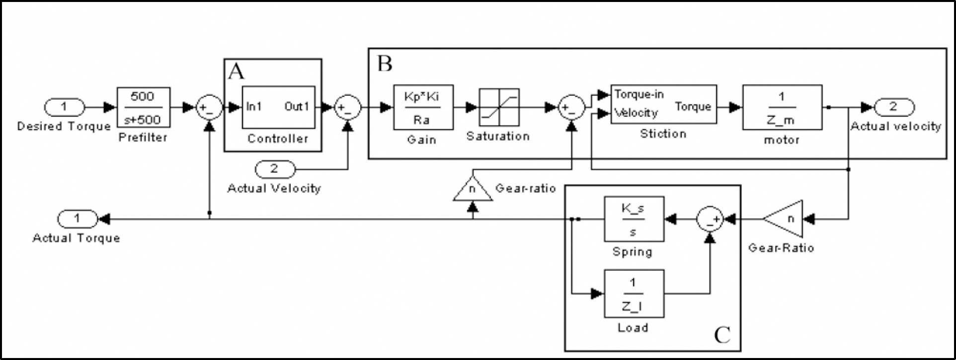
Control block diagram of actuator.
An electrical DC motor is chosen as a force generator element in the actuator. The electrical DC motor is an electromechanical transducer. The current I and the voltage E as an electrical part will generate the torque applied to the mechanical load.


Here Ki is the electromechanical conversion coefficient which is equal to the ratio of the torque to the applied current which is also equal to the ratio of the stall torque to the maximum velocity of the DC motor. Parameter Kemf is the back electromotive force constant which is equal to torque constant. The parameters T, Ra, I, ω are DC motor output torque, winding resistance, applied current, and motor shaft angular velocity, respectively. The moment of inertia of the rotor, J, and the viscous friction in the bearings, b, are measured while the electrical winding is open. The input voltage E is reduced by back electromotive force Kemfω also drops across the winding resistance Ra. It can be seen that:

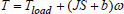
Where Tload is the load's reflected torque on the motor that is determined by actual force on the load, the gearratio and efficiency of the gearbox installed on the actuator. For backdrivable gearboxes: Tload = μnTl where Tl is actual torque at the output of the actuator, n and μ are gear ratio and gearbox efficiency, respectively. Also the value of Tload is directly related to the coupling's deflection and load's dynamics (Fnertia and damping properties). As mentioned before implementing a velocity controller is a part of actuation system design that is explained in the following part.
Nowadays, velocity control of the DC motor is a conventional routine in robotics and automation industry by using amplifiers and velocity feedback sensors (such as encoders and tachometers). The effects of coupling-load interaction dynamics and stiction on the velocity control of the DC motor are investigated as major concerns of compliant actuation system. Analyzing the effects of load and compliant element provides us a proper view on how to design the actuators for different applications.
Parameters Zm and Zl shown in Fig. 7 are motor and load impedances, respectively. Values of Zm, Zl and K are given below for convenience:


Where Ka and Ki are amplifier gain and motor torque constant, respectively. The damping ratio of the DC motor includes viscous and back electromotive force damping which is given below:

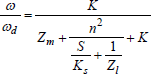
The closed loop transfer function of velocity controller can now be shown to be:
Where Ks and n are the coupling stiffness and gear ratio of the actuator respectively.
Columb friction and suction are dramatically affected by introducing the AASC and the DC motor will not move until the torque will be higher than the suction torque. So the effects of suction are considered in the modeling of the actuator as shown in Fig. 7. Also the parameters of the DC motor and controller that are used in the simulations are shown in Table 1.
Parameters used in this paper.

Due to the effects of flexible modes, the transfer function has two complex zeros and two complex poles. Also the transfer function has one real pole caused by DC motor's inertia and damping values. Since the flexible modes of the load are lightly damped, the responses of the system described by Eqn. 12 exhibits a sharp peak and a notch on the phase response plot and a sharp notch on the magnitude plot of the system as illustrated in Fig. 8. To reduce the peak and notch shown in Fig. 8 it is found increasing the amplifier gain increases the damping ratio of the system and decreases effects of flexible modes of compliant. Moreover, the steady state error of the system and the sensitivity of the system to the dynamics of the load are lowered as can be seen in low frequency response of the system in Fig. 8. On the other hand increasing the saturation of the amplifier (increasing the difference between the actual and saturated signal) is equivalent to decreasing the amplifier gain whenever the amplifier is saturated. Thus, saturation confines the performance of the system. Preventing the saturation is possible by setting limitations for commanded velocity signal that has direct interaction with tuning the torque controller gains. So the task manager block should be reasonably designed by dictating the desired torque values with respect to the actuator's limitations. For example by increasing the desired frequency, the desired magnitude must be decreased. The specification of the torque controller loop is the remaining question for designing a torque (or force) controller using velocity control of the DC motor that will be explained in the next part.

Bode plot of velocity control loop.
The task manager block sets the commanded torque to the actuator. Then, a prefilter reduces the sudden changes of the commanded torque. Actual torque of the actuator is measured by the coupling's angular deformation. By differentiating the desired torque from actual torque, set values of torque error is provided for the torque controller unit. The torque controller unit is designed by considering the following facts: (1) Maximum angular velocity of the DC motor is limited as a result of amplifier saturation. (2) The power of the DC motor is limited. (3) The closed loop gain of the system should be fixed for different value of the coupling's stiffness. (4) Flexible modes caused by compliant element should be manipulated.
A controller is developed here by accounting the above characteristics of the system. AASC causes the stiffness of the coupling to be adjustable according to the following relation:

Parameter ρ is determined from the distance between the spring position and center of rotation as mentioned in Eqn. 3. Therefore, in a system point of view, the system has different closed loop gains for different values of stiffness; i.e., the higher the stiffness, the higher the closed loop gain. So, keeping the same performance is possible by increasing the controller gain when the coupling's stiffness is decreased and vice versa. Also higher gain selection caused the desired velocity signal to be higher than the maximum velocity of DC motor that can be manipulated by saturating the controller output signal. Respectively, the structure of the controller is designed based on the factors above and is illustrated in Fig. 9. Proportional-Integral controller is used to compensate the torque error. Values of Kp and KI are determined from maximum desired velocity. As shown in Fig. 9, tanh saturation functions are used to limit the error amplification:


Where the k = 5 is assumed constant. By employing a dead zone function at the output of the controller, the angular velocity command is always kept below the maximum velocity limit. So the output value of the dead zone function is zero if output command is less than maximum DC motor velocity and is 1 if the output value is larger that amount.

Schematic of torque controller.
One significant deviation from the ideal model occurs when the actuator saturates. ACSEA actuator saturation represents the threshold above which the DC motor can no longer compensate for the phase and magnitude error of the actuator or the amplifier could not produce enough current to compensate the velocity error. This effect is illustrated as a bode plot in Fig. 10. On the other hand, increasing the saturation of the amplifier is equivalent to the decreasing the amplifier's gain whenever the commanded velocity error is constant. So the effect of saturation can be seen as both magnitude and phase errors in the resulting actuation response by changing the amplifier gain from k = 0.015 to k = 1.5. As illustrated in Fig. 10. by decreasing the amplifier gain (equivalent to increasing the saturation) the bandwidth of the closed loop system is decreased. Also the oscillatory modes in higher frequencies, cause by flexible modes, are appeared. As mentioned before limiting the control input by a tanh function could rather accomplish to prevent the saturation of the joint actuator from occurring. But this approach is taken when there is no outer closed loop task management. In the case when there is a control loop wrapped around the actuation, proper sizing of the actuator with respect to the given manipulator tasks is required to prevent the actuator saturation.

Bode plot of the closed loop control system.
The effects of the load's inertia on frequency response of the close loop system as a bode plot is shown in Fig. 11 by increasing the load's inertia from initial value of

Bode plot of the closed loop system with different load's inertia.
The goal of the simulations is to investigate the overall performance and benefits of the actuator design. MATLAB and SIMULINK were used to perform actuator simulations for several test cases as used before to provide the frequency response of the system. To simultaneously account for linearized response of the system without considering the saturation, the simulations were done using the LTI package of MATLAB. Variable step ode23t was chosen for numerical integration and solve the equations. The DC motor is chosen from the ones fabricated Maxon motor that the parameters of the DC motor and controller are summarized in Table 1. The desired value of the torque is a sinusoidal signal which followed by a prefilter to dampen the sudden changes of the input. Following sections introduce special case study to demonstrate the performance of the actuator.
Tracking the desired torque
In this section, the performance of the system with respect to variable sinusoidal signal is discussed. So, the commanded torque signal with constant magnitude of 1NM is considered and its frequency is changed gradually from 0Hz to 50Hz in a period of 1Sec. The load inertia and the coupling stiffness assumed:
The response of the actuator for the higher desired torque magnitude, 5NM, is shown in Fig 13. As illustrated in Fig. 13-a, the actuator can successfully track the commanded torque at high frequencies but the actuator can not respond to the very low frequency input signals. The reason is that the load will accelerate and its velocity becomes larger than the maximum velocity of the DC motor, and therefore, the actuator could not follow the load then the magnitude response will be less than the commanded value. This limitation is because of amplifier saturation. The saturation effects on velocity response can be seen in low frequency response of part b of the Fig. 13.

Actuator's response to the desired torque.

Actuator's response to high amplitude desired torque shows saturation.
The above results illustrate that the actuator could successfully response to the commanded torque signal and also demonstrate the importance of matching the desired signal with actuator limitations. It can possible by proper task planning with respect to the actuator limitations in example: by proper trajectory generation.
Natural looking motion that is generated by the physics of the robot is desirable in several kinds of robotic applications such as walking machines and exoskeleton systems. So the feature of varying the stiffness in a wide range adds to the benefits of the actuator in such application. To simulating the natural dynamics, when the minimum interaction with actuator is desired, the magnitude of the commanded torque is assumed equal to zero. In this case the load is considered as a pendulum and the gravitational effects are taken into account. The initial angular velocity of the pendulum assumed

Passive motion of the load and actuator effects on load motion.
This section of the simulation illustrates the effects of the mechanical stiffness on the actuator's impedance. The active controllers (Torque and velocity) with the zero commanded torque is assumed. Then the external sinusoidal torque with magnitude of 1NM and the frequency of 6Hz is applied on the load. Finally different values of coupling's stiffness are chosen. As a result the torque measured on the load is illustrated in Fig. 15-a. And the commanded and actual velocity of the DC motor is represented in Fig. 15-b.

Zero desired torque and external torque applied on the load.
So for the lower stiffness values of the coupling the actuator impedance will be smaller and the effects of the actuator on the load will be minimized. The reason could be the lower effects of velocity error of the DC motor whenever the stiffness value of the coupling is smaller. Finally this section is supporting that the capability of changing the mechanical stiffness of the actuator is very useful for the low impedance robotic systems applications.
We have introduced a new actuator design for environmental-interaction based robotics systems, referred to as
We have proposed the new method to control the commanded torque (or force) of the actuator by converting the traditional current control method to velocity control of the DC motor. Although the new method of controller is very simple but it significantly maintains the high accuracy for controlling the torque (or force). By changing the controller gain with respect to the coupling's stiffness of the actuator, an almost pure torque source has provided for the wide range of applications.
Performance of the actuator for different desired tasks has tested by simulation. The result shows the very good performance of the actuator that provides a strong proof of concept of this actuation system.