
Abstract
An anthropomimetic robot is one that closely copies the mechanics of the human body by having a human-like jointed skeleton moved by compliant muscle-like actuators. This paper describes the progress achieved in building anthropomimetic torsos in two projects, CRONOS and ECCEROBOT. In each, the bones were hand-moulded in a thermoplastic and the muscles were implemented by DC motors shortening and extending elastic tendons. Anthropomimetic robots differ from conventionally engineered robots by having complex joints and compliant tendon driven actuation that can cross more than one joint. Taken together, these characteristics make the robots unsuitable for control by standard methods, and so the ability to model them is important for developing heuristic methods of control and also for providing forward models. The robots were modelled using physics-based techniques which enable the study of the generation of movements and also of interactions with arbitrary objects. The lightweight and compliant structure of the robots was found to be safe for human proximity and contact.
1. Introduction
The anthropomimetic concept [1] grew out of the requirements of the CRONOS project [2], which investigated the possibility of creating a conscious robot. The theoretical position behind the project was that human consciousness was thought to depend on the brain's internal model of the body. What was required, therefore, was a robot that had an internal model of itself that was as close as possible to the human brain's model of the human body, and this in turn required the robot to be as close a model of the human body as possible. Since the internal model was intended to be used to simulate possible actions in relation to a model of the real world, it was decided to neglect the metabolic aspects of the body and to concentrate on its ability to act. This implied that the robot, CRONOS, and its internal model, SIMNOS, should be limited to the sensory and mechanical aspects of the skeleton and its actuation.
In the design process of a normal humanoid robot, priority is given to the ability to control the robot using the conventional engineering methods that have been developed in the last few decades. Joints are therefore reduced in number and simplified, actuation is by stiff precision motors and gearboxes, and accurate sensors report on the position and velocity of all mechanical components. However, the human body obeys none of these standard engineering principles and CRONOS was emphatically not designed to enable control, but to copy the structure of the human body. In effect, we were creating a problem that we would then have to solve.
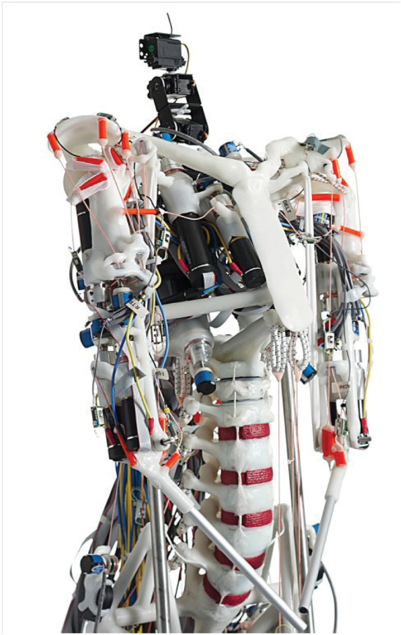
Considerations of feasibility led us to restrict CRONOS (Figure 1) to a human-sized torso, mounted on a powered, wheeled base. The structural framework modelled the human skeleton as far as possible, with individual bones, joints and other tissues being modelled accurately wherever it was thought to be important. Feasibility constraints imposed some simplifications, such as a reduction in the number of vertebrae and a change in their proportions (see Figure 1), and abstractions were used where there was no specific role in producing movement, as for instance in the rib cage. The main tendons and muscles were modelled as lengths of sleeved natural rubber – the tendons – which were stretched and relaxed by winding their inelastic terminating cords onto spindles driven by DC electric motors – the muscles. The insertion points of the tendons and muscles were matched as far as possible to those of their biological counterparts.
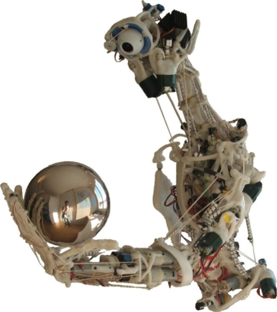
The original CRONOS prototype. Note the reduced number and increased length of the neck vertebrae.

SIMNOS. The coloured arrows show the instantaneous values of various parameters. The lower left quadrant shows the rendered view from SIMNOS's eye.
Our early experiments with CRONOS quickly made us aware that it was quite unlike conventional robots. In the absence of closed-loop control of every muscle, the passive compliance of the tendons and the high number of degrees of freedom meant that any external disturbance or motor activation, even of a single motor, would produce a whole-body response as the inertial and gravitational forces were transmitted through the structure. This had both positive and negative features. On the positive side, this could appear as a whole-body coordinated movement, with a peculiarly human quality. On the negative side, the lack of intrinsic damping produced characteristic oscillations reminiscent of the action tremor seen in certain neurological conditions [3] SIMNOS, CRONOS's internal model of itself, used a proprietary physics-based modelling system, NVIDIA PhysX [4]. Its limitations meant that it did not permit CRONOS to be modelled exactly, and so some complex structures like the shoulder girdle had to be omitted, but the overall qualitative behaviour was very similar to that of CRONOS. Although the goal of consciousness was not reached within the project, the combination of CRONOS and SIMNOS was used successfully in an implementation of a form of imagination [5, 6]. We already knew that SIMNOS was at best a qualitative simulation of CRONOS, and it was therefore difficult to use SIMNOS as had first been intended, as part of a search procedure for the motor activations for task-achieving actions. We managed some proof of concept experiments [5, 6], but only after a long and careful setup, and a severe restriction on the range of possible movements. However, by using one copy of SIMNOS in place of CRONOS and another copy as the internal model of the first copy, we could carry out virtual experiments in which we varied the parametric accuracy of the internal model's simulations [6]. In this way we were able to show that for some tasks, such as throwing an object over a barrier, the search could yield useful results even though there were substantial differences between the substitute robot's world and the internal model's.
The interesting possibilities suggested by the CRONOS project led to a follow-on project, ECCEROBOT [7], which mainly focused on the purely robotic aspects of the anthropomimetic concept. Before moving on to the description of the project, we should note the many similarities between our work on the anthropomimetic robots CRONOS and ECCEROBOT, and the work at the University of Tokyo on the musculoskeletal robots Kenta, Kotaro and Kojiro [8, 9, 10]. Although there are some differences in motivation and scope (for example, the musculoskeletal work is somewhat less influenced by biomimetic forms, and the robots have legs) the two lines of research are dealing with common problems, and the technical and computational solutions are essentially complementary.
In this paper, Section 2 gives an overview of the motivation and nature of the work carried out within the ECCEROBOT project. Section 3 identifies four key principles of anthropomimetic design and describes how they were applied in ECCEROBOT. Section 4 describes the design and physical construction of the series of robot prototypes produced within the project. Section 5 deals with the physics-based modelling of one of the prototypes. As well as being a central component of the project, the modelling generated images that reveal a much clearer view of the robot's constructional and functional components than the complex images of the robot itself. Finally, Section 6 sets out some of the things that were learned from the project and indicates the most fruitful paths for future research.
2. ECCEROBOT: Embodied Cognition in a Compliantly Engineered Robot
The ECCEROBOT project had three explicit aims: to design and build an anthropomimetic mobile robot; to characterize its dynamics and control it successfully; and to explore and exploit its human-like characteristics to produce some human-like cognitive features.
The work to achieve the first aim, to design and build an anthropomimetic mobile robot, was grounded in the approach taken with CRONOS. A reference point for improvements, and also a platform for early control experiments, was provided by refurbishing CRONOS and renaming it ECCE1. The first prototype developed within the project (Figure 3) was the ECCEROBOT Design Study (EDS), a more complete and anatomically accurate torso than ECCE1, but using the same motors, motor controllers, elastic materials and construction methods. The second prototype, ECCE2 (Figure 6) had a simplified anatomy and served as the main functional integration platform for the sensors and motor controllers. It also trialled new motors and elastic materials. The final prototype, ECCE3 (Figure 7) featured fully integrated electronics, an improved and more anatomically correct shoulder assembly, improved tension sensors, and a mobile base.
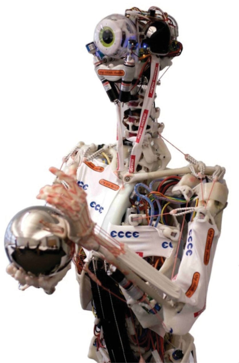
Front view of the ECCEROBOT Design Study (EDS).
To deal with the second aim, three approaches to control were investigated: classical control theory; heuristic methods (search, learning, evolutionary algorithms) using a physics-based simulation of the body; and sensory/motor control. Although good progress was made in applying classical methods as far as this was possible [11], some of the features of anthropomimetic robots (multi-articular actuation and complex joints – see below) defied current analytical techniques, thereby forcing our attention onto more heuristic approaches [12, 13]. To date, the sensory/motor investigations are limited to exploring the emergence of reflex-like controllers from simplified low level systems [14].
The final aim, to explore and exploit the robot's human-like characteristics to produce some human-like cognitive features, is still on the horizon, but it is likely that the technology developed within ECCEROBOT will be able to support such an investigation.
3. Principles of anthropomimetic design
In setting out to design an anthropomimetic robot, it is not enough to resolve to copy the mechanical structure of humans, as it will always be necessary to compromise because of technical limitations. In deciding which features to include and which to omit, it is useful to have an awareness of what differentiates an anthropomimetic robot from a conventional humanoid robot. Within the project, four principles of anthropomimetic construction have been identified [15]: tendon-driven redundant actuation, multiple joint actuators, compliance and complex joints. These can be briefly summarized as follows.
3.1 Tendon-Driven Redundant Actuation
In a typical humanoid robot the actuators are positioned at the joints, with each axis of rotation at the joint being controlled by one motor. In contrast, the human body moves its limbs using tendon-based techniques, with contractile muscles attached to bones via elastic tendons. During contraction, a muscle exerts a force on its anchor points which will, if it is high enough, cause some relative movement of the bones to which it is attached. Muscles are asymmetric – they can only pull, not push – and so the bidirectional control of a given degree of freedom requires more than one actuator in some kind of antagonistic arrangement – in other words, actuation is typically redundant.
3.2 Multi-articular Joint Actuators
Although many muscles only provide actuation at a single joint, the human body also has muscles spanning two or more joints. For example, the biceps is attached to the scapula and to the radius, crossing three joints: the shoulder, the elbow (flexion) and the proximal radioulnar joint (supination of the forearm). Its primary role is the supination and flexion of the forearm, but it also has several effects on the shoulder (abduction, adduction and stabilization). In order to capture fully the character and interrelatedness of these actions, an anthropomimetic robot should ideally include the whole, complex biceps' structure.
3.3 Compliance
In order to achieve precise control, conventional robot actuators are typically stiff and heavy. As is well known, this makes them vulnerable to shock loads and also intrinsically dangerous to humans. In contrast, the human body uses compliant and relatively lightweight muscles and tendons for actuation, and an anthropomimetic robot should do likewise. Although this brings the advantages of safety and robustness, these are incidental to the main point, which is that the interaction with the environment has to be managed via compliant mechanisms, and so all the resultant complications which have been engineered out of conventional robots must be tackled head on. The elastic nature of muscle systems is usually represented as an arrangement of lightly damped springs, as in the widely used Hill muscle model, and it is certain that no engineer aiming for precise control of a multi-jointed system in an open environment would specify an actuator with those characteristics.
3.4 Complex Joints
The joints of conventional humanoid robots usually have clearly identifiable axes of rotation, as from the classical control point of view this allows their motion to be dealt with in a tractable and familiar mathematical framework. However, the human body has several joints which do not match this description. For example, in the shoulder girdle (the clavicle, scapula and humerus), the scapula is connected to the sternum via the clavicle, but is retained mainly by ligaments and muscles. This arrangement produces a wide range of motions, both rotations and translations, that are difficult to classify or to relate to other structures.
3.5 Implementation of the Principles
As far as is practicable, the components of an anthropomimetic robot should match those of the human body in position, proportion, degrees of freedom and passive and active performance. Nevertheless, many simplifications can be made on principled grounds. For example, as the robot will have no lungs, it will not need any ribs; however, as the scapula slides over the back of the rib cage, it will need a corresponding surface for the robot scapula to slide over. Many details of the shapes of bones between the joints at their ends do not matter, since all that is required is that the connection is rigid, and so engineering convenience can replace natural form. Although the spine normally consists of 24 separate vertebrae, some people have one more or one less. This makes no functional difference, since the spine acts as a single complex flexible element, and so an anthropomimetic robot need only have enough vertebrae to model the spine with sufficient functionality and qualitative fidelity.
In most instances of simplification or omission of a feature, the driving force is the inability to match the biological system in terms of size, performance or complexity. The anthropomimetic enterprise sounds daunting when one considers that the skeleton of an adult normally contains 206 bones and approximately 650 separate muscles. In fact, modelling the skeleton is comparatively straightforward, at least as far as the larger bones are concerned. However, many joints are held together (and in the case of the vertebrae, separated) by ligaments or tough soft tissues which are almost impossible to duplicate. For example, the wrist joint alone involves more than a dozen bones held together in this way. For their size and weight, muscles are much more powerful than any equally controllable artificial source of actuation and it is literally impossible to duplicate every one of the skeletal muscles with an engineered equivalent.
Taken together, factors such as these mean that a feasible anthropomimetic robot must necessarily fall short of being a completely faithful model of the functional human anatomy. However, this need not in any way devalue the idea. Provided that the four key characteristics are present wherever possible, the robot will present all the control problems that a perfect robot would involve, and once these are solved, any emergent properties of the anthropomimetic embodiment should be revealed.
Building a series of robots also offers the possibility of evaluating different combinations of structures in different robots. For example, the human forearm consists of two bones, the radius and the ulna, whose main function is to achieve wrist rotation. They do this by rotating around one another. If this scheme is implemented on a robot, the relative movement of the bones makes it impossible to fit enough motors in the forearm to control the hand. However, by building two robots, one with a radius and ulna along with a simplified hand, and one with a traditional robotic wrist rotation and a complex hand, it is possible to study both. An example of this idea is the original CRONOS, which had one shoulder with a complete clavicle, scapula and humerus assembly, and one shoulder with a fixed socket for the head of the humerus. This enabled us to appreciate the value of the floating scapula for raising the arm as high as possible.
Many examples of the principles set out in this section can be seen in the next section, which describes the physical manufacture of the ECCEROBOT series.
4. Physical manufacture of CRONOS and the ECCEROBOT series
4.1 CRONOS/ECCE1
The design brief for CRONOS was to build a torso as mechanically similar to a human torso as was feasible within the constraints of time and budget. After reviewing the options, the optimal solution for building the skeleton seemed to be to manufacture each bone by hand using polycaprolactone [16], a type of engineering thermoplastic marketed in the UK as Polymorph. Polycaprolactone is polythene-like in many ways, but when the granular form is heated to 60 degrees centigrade it fuses (or softens, if already fused) and can be freely hand moulded for quite some time before resetting at around 30 degrees. Its appearance when cold is distinctly bone-like. As it is a true thermoplastic, it can be reheated and remoulded as many times as is necessary. Most importantly, it is possible to soften it locally using any directed source of heat, and this enables it to be joined to other Polymorph structures or to a variety of other materials, facilitating the progressive assembly of larger constructions.
Polymorph can also be readily moulded around other components and materials. For example, it can be used to form a ball and socket joint by moulding it around a metal sphere mounted on a rod. It contracts slightly on cooling, and so can form tight joints when moulded around other components. Its tensile strength is good – Polymorph has the highest tensile strength of all the capralactones, at 580 kg/cm2 – and in practical engineering terms it is tough and springy. It can be further strengthened (and stiffened, if necessary) by adding other materials, such as wire, metal rods or bars, and it can be given a workable grain by stretching, folding and rolling.
Once it had been decided which bones to model and at what level of detail, they were hand moulded using information from Gray's Anatomy and other sources concerning their shape and dimensions. Joints were simplified where necessary, but it proved possible to reproduce most of the degrees of freedom with relatively few problems. In fact, the major constraint turned out to be the placement of the muscles. Every effort was made to make this accurate, as much of the character of human biomechanics comes from the positions of the termination points of the muscles and tendons in relation to the joint (or joints) in between. However, the size of the actuation components, and the requirements of maintaining clear tendon runs as the skeletal components moved, made compromises inescapable.
In order to provide muscle-like compliant actuation, we took advantage of the mass production of a common domestic device – the electric screwdriver. These are designed to produce torques of around 3–5Nm from NiCad battery packs of 6V nominal voltage, and the direction of rotation is electrically switchable; backdriving against the set direction is prevented by a sprag clutch. The elastic element in CRONOS was provided by marine grade shock cord – a sleeved natural rubber core available in a number of thicknesses. For light loadings we used a 5mm type and for heavier duty a 10mm version. The shock cord was terminated at each end by 3mm thick braided Dyneema kiteline with a working breaking strain of 250kg. This material, also known as Spectra, is a heavy molecular weight polyethylene (HMWPE), 40% stronger than Kevlar and with negligible stretch. By winding the kiteline round a 10mm spindle driven by a good quality screwdriver motor and gearbox, we could achieve tensions approaching 500N. The maximum current draw was of the order of 20A, which was handled by customized motor controllers originally designed for the model industry.
The refurbishment of CRONOS to form ECCE1 was mainly to provide increased usability and did not affect any matters of principle.
4.2 The ECCEROBOT Design Study (EDS)
The EDS was intended as the mechanical prototype for the rest of the ECCE series. It was the first anthropomimetic robot to feature twin floating shoulder blades (see Figure 4). It also has a greatly improved lumbar spine design with an accurate representation of the vertebral disc, including the fluid-filled centre. One unforeseen consequence of this is that the robot has subsequently developed a mild scoliosis, or curvature of the spine (see Figure 4), and has to be laid down overnight to prevent extended compression of the discs and thus improve the longevity of the spine. The robot also features an accurate copy of the skeletal structure of the neck, differing only by the number of the vertebrae being reduced to four and the atlanto-occipital being rendered as a set of nested pivot points (Figure 5).
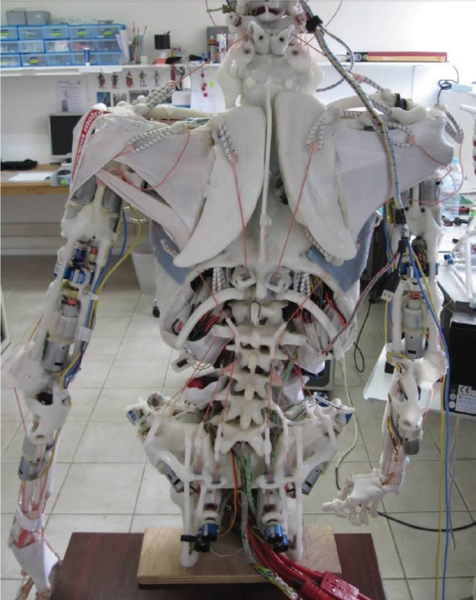
Rear view of the EDS. Note the floating shoulder blades and the slight curvature of the spine (scoliosis).
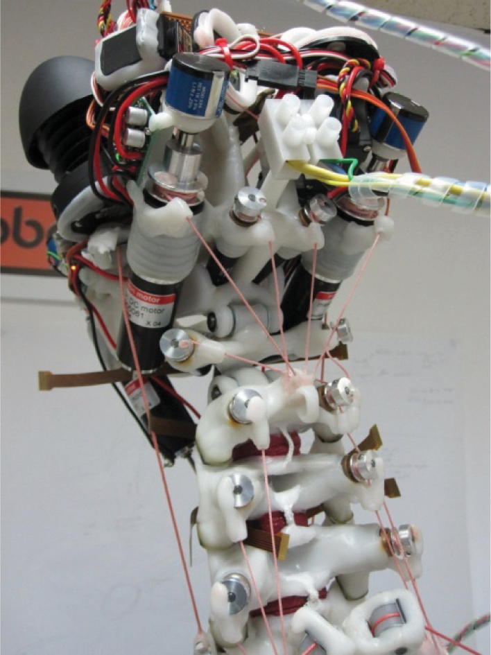
The neck of the EDS, showing the realistic spinal structure.
ECCE2 was mainly dedicated to prototyping the sensing and control, but also had new motors and a new tendon material.

The completed ECCE3.
The EDS has 40 powered degrees of freedom in the body and an additional 20 in the head and neck (although only eight of these are in service due to a lack of suitable electronics hardware at the time of manufacture). The actuation method (custom motor drivers, screwdriver motors and gearboxes, kiteline, and marine grade shock cord) is identical to that used in CRONOS. The main sensors are multi-turn potentiometers on the output shaft of each gearmotor which allow positional control via a custom-written sequencer. Despite the simplicity of this scheme, the necessary scripts can be surprisingly complex: even a simple gesture like raising an arm requires the timed control of a dozen or more motors in different parts of the body. The single movable eye/camera, an improved version of the CRONOS visual system, was equipped with face detection and a simple habituation mechanism, so that it could move the head and eye to fixate on a face in a crowd and then move on to fixate on another after a few seconds. The hands are provided with touch sensors that enable a scripted handshake when appropriately activated. In more than two years of exhibiting and demonstrating the EDS, involving exposure to and physical contact with thousands of people of all ages, the robot has proved several things about the anthropomimetic concept. Perhaps the most important is that, because of its lightweight build and its compliant actuation, the robot is intrinsically safe. In addition, for reasons which are not yet entirely clear but which deserve investigation, people are fascinated by its appearance and the way it moves, and are often keen to interact with it – again, this is only an advantage because it is safe to do so. Finally, it has proved exceptionally robust because the whole-body compliance protects the individual parts from excessive or sudden loads. Although none of these factors is scientifically significant, they are clearly of immense practical importance for any robot that is to interact with people.
4.3 ECCE2
The next robot, ECCE2 (Figure 6) investigated improved proprioception and alternative materials and motors for providing actuation, as well as serving as the testbed for the functional integration of the distributed sensing and control electronics [17]. In order to allow unrestricted access to the electronic circuits, they were not integrated into the body of the robot, but were placed externally.
The thickness of the resultant cable bundle interfered with the free movement of the robot's spine, but this was of little consequence as the focus of this prototype was on integration rather than performance.
The new motor control circuitry, with several built-in control modes, was paired with new high quality servo motors and gearboxes (Maxon RE25 and HP22) with matching encoders, giving vastly improved control and performance. As the encoders were incremental, the multi-turn potentiometers were retained to provide a datum for initialization. A critical aspect of the new motor/gearbox arrangement is that it is backdriveable, and so, as with human muscle, all force has to be actively produced. However, this improvement comes at a price, because without any actuation, the robot will collapse, whereas with CRONOS and the EDS, the robot retains its posture indefinitely if power is lost.
To make the most of its compliance, an anthropomimetic robot needs information about the tension in each of its muscle units. This can be calculated from the parameters of the elastic material if its extension is known; we fitted length sensors to some muscle units to enable this to be done. However, since the determination of the lengths of some muscle cables is difficult because they are routed over bones that change position, we also developed a method for direct measurement of tension. With the aim of retrofitting a tension sensor to the previous robots, we procured a custom made strain gauge assembly that could be clipped onto the kiteline. Although apparently satisfactory at first, its outputs were too sensitive to variations in its exact position on the braided surface of the kiteline and this inconsistency rendered it useless in practice. A further difficulty was that for some muscle cables it was impossible to find a place on the cable to mount the sensor that was not disturbed by contact with either a bone or another muscle cable during movement.
Although the marine shock cord used previously had proved satisfactory in use, its bulk and difficulty of termination in Polymorph created problems in manufacture. A number of materials were examined for their suitability and both polyurethane and nitrile rubber appeared promising. Polyurethane was preferred because it bonded well to Polymorph, whereas nitrile rubber had to be glued with a cyanoacrylate. In Figure 6, it is possible to see how the muscle cables have been smoothly routed over the right shoulder in a way that would have been impossible with shock cord. However, in further tests it appeared that the particular type of polyurethane used could show significant creep. While this would not matter in most circumstances, it would mean that any attempt to match the physics-based simulation of the robot with the real robot would have to be subject to constant online adaptive calibration, which is a situation best avoided.
An additional aspect of the elastic material is the shape of its length-tension curve. The shock cord is linear throughout most of its range, whereas the passive length-tension curves for both tendon and passive muscle are roughly exponential. For the relatively small forces and displacements involved in our work, the shape of the curve will make very little difference, but for tasks in which nonlinear passive stiffness may be critical, it might be necessary to select an elastic material with properties better matching those of the relevant human tissues. In this case the best candidate would be the exponential curve of rubber nitrile, rather than the logarithmic curve of ECCE2's variety of polyurethane
Omitting the floating shoulder blades from ECCE2 also allowed the mounting of a powered version of the internal rotator, the subscapularis (which covers the inside of the scapula), which on ECCE1 and the EDS had been represented by a passive element. Although the total shoulder movement is reduced by the lack of shoulder blade movement, the available actions at the shoulder joint itself are much closer to human reality.
4.4 ECCE3
In ECCE3, the final hardware output of the project, we integrated the improvements made in the previous prototypes, made some further alterations to correct problems that had been identified, and mounted the robot on a powered, wheeled base (Figure 7).
In ECCE3, the clip-on strain gauge sensors were replaced by miniature high specification load cells [18]. By locating them at one end of the muscle assembly, the problem of collisions with other bones and cables was avoided. The polyurethane elastic material used in ECCE2 was replaced with a different polyurethane in the form of flexible tubing, which was not subject to creep. By attaching this directly to the load cell (see Figure 8) it was possible to make very short muscle units which were particularly useful in the shoulder complex.

The lumbar spine of ECCE3 from the rear during construction. Note the 14 large motors and the extended spinal processes carrying the miniature load cells which are directly attached to the polyurethane tube elastic elements.
In the EDS there is a tendency for the shoulder joint to dislocate which has been addressed in ECCE3 by the addition of a single passive element, equivalent to the long head of the biceps. which passes over the top of the ball and attaches to the upper edge of the socket. The geometry of the four main muscles of the rotator cuff has been refined to improve range and stability, with additional changes to reduce friction where the tendons run over the ball. The result is a smoother action with increased resistance to dislocation.
The range of motion and the freedom of the shoulder blade to glide on the back of the thorax has been significantly improved in the ECCE3. This allows for an investigation of the complex interaction between the movement of the arm and the movement of the blade. A relatively simple example is the manner in which the blade rotates to remain directly beneath the arm when it is raised to provide a stable base. A more complicated example is the timing of movements to maximize the dynamic stiffness of the arm and shoulder during fast forward reaching movements.
To correct the scoliosis that had developed in the EDS, each of the vertebrae in ECCE3 is actuated by a pair of muscle units equipped with load cells (Figure 8). The upper three vertebrae give a wide range of motion and the lower two are able to pull the spine up and backwards to resist the tendency to sag. By balancing the forces laterally it is possible to ensure alignment between the successive vertebrae and thus avoid excessive curvature of the spine in the coronal plane (side to side).
However, a single physical robot is not necessarily the best platform for developing a robot controller or for exploring the consequences of structural or parametric changes. The next section of this paper describes our response to the related and, in our view, necessary task of building a software model of an anthropomimetic robot. A key additional benefit of including the next section is that the model reveals many structural and functional details of an anthropomimetic robot (the EDS) that cannot be seen in the images of the assembled robots presented in this section.
5. Developing a physics-based model of the EDS
In this section we present work undertaken to create a detailed, full-body, physics-based simulation model of the EDS. The model was created for three main purposes. Firstly, to provide a realistic, comprehensive test platform for developing effective control methods applicable to a whole-body biomimetic robot with compliant actuation. In particular, we are interested in macro control issues or features that do not clearly manifest themselves in studies considering small numbers of joints [19, 20]. Secondly, to develop a model that could be integrated as a module into a control architecture, for use as a motor planning resource or acting as a state-predictor within a delay compensation mechanism [21]. Thirdly, to investigate whether such an extensive highly dynamic structure can be usefully modelled within a standard physics engine, to produce a stable and comprehensive simulation running in real time or better speed while incorporating all the main features of interest.
5.1 Reverse Engineering the Robot Structure
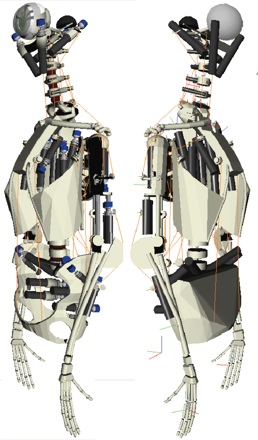
As no CAD data were available for the components and assembly of the EDS, the entire robot structure had to be reverse-engineered into a 3D modelling tool (Blender [22]) using an array of detailed photographs, measurements and videos. Data capture was limited to the shape and relative orientation of the major components, namely, bones, motors, joints, pulleys and muscle cable runs and attachment points. The completed static model is shown in Figure 9. Alternate capture approaches, such as laser scanning and attachment point calibration using evolutionary algorithms, were also trialled against a minimal test rig arm with some success [23], but the method was not feasible for the assembled EDS.

Reverse-engineered static model of ECCERobot torso.
5.2 Dynamic Simulation via Physics Engine
Employing an off-the-shelf physics engine offered practical advantages over developing a custom analytical model. Support exists already for a range of rigid bodies and joining constraints and dynamic models can be constructed using existing standard modelling tools, 3D viewer libraries and file archive formats. Large complex models are a realistic option as performance is generally high since the engines are designed for real time game simulation and speeds are increasing through the widespread adoption of GPU acceleration. Furthermore, they offer a direct integration of an environment with the modelled robot for such applications as collision-free motion planning. Indeed, later ECCEROBOT prototypes were designed to capture and integrate the live environment via a head-mounted MS Kinect sensor [24].
Bullet Physics [25] was selected as the physics-based modelling platform offering the best combination of a flexible, extendible C++-based architecture, open source status and a fast impulse-based design. Impulse-based simulations are simpler, and therefore faster, than constraint-based schemes, as net forces can be easily calculated as the sum over a short timestep of the separate impulses of all the contributing bodies. Constraints, such as joints, are implemented by issuing resisting impulses after constraint violations rather than solving for absolute constraint rules. Although it is fast, the method is potentially problematical as joints can behave in an elastic-like manner or even break under a large and sudden force.
5.3 Simulating the Passive Structure
The static model of the robot (Figure 9) in Blender was migrated to Bullet one component at a time via the standard COLLADA 3D file format [26]. The components were then successively joined with the appropriate constraints to form the passive unpowered robot model. The physics model was continually tested for stability as each component was added. Wherever practical, the custom mesh shapes of the Blender model were replaced with one or more primitive bodies (cylinders, cuboids, spheres etc.) to speed up collision checking (see Figure 12). Bone masses were extrapolated from the known material density and volume. Compound bodies, such as the metal motors and gearboxes mounted on polymorph bones, were modelled by a single compound collision shape with the centre of mass and inertia tensor calculated from the combined mass and shape of each component [19].
One particular point of note is the shoulder assembly or shoulder girdle. The fully floating scapula (Figure 10) is connected to one end of the clavicle and is held in place only by the muscle cables wrapped around it (see next section). This end of the clavicle is supported only by the trapezius muscle cable hanging from the neck, while the other end is joined to the sternum. These structures would be very difficult to model analytically, but easily lend themselves to this class of physics engine, where it can be seen that this complex and freely moving assembly settles into a surprisingly natural and stable state only when the muscle cable simulations are introduced. The stability and naturalness are probably a consequence of the attention to detail in modelling the robot directly from human anatomy.

Physics-based model: the floating shoulder blade and arm hang from the collarbone (red constraint), held by wrapping muscle cables (orange).
The upper (neck) and lower (lumbar) sections of the spine are formed of individual vertebrae which are joined with additional ligaments to avoid S-curve collapses.
Static joint friction was simulated using the joint motor feature of Bullet to briefly hold the joint angular velocity at zero. Joint friction while moving was simulated by applying at every timestep an opposing angular impulse proportional to the joint angular velocity.
Bodies joined only by lengths of inelastic kiteline, such as the shoulder blades hung from the collarbones (Figure 10), were modelled using 6DOF constraints.
Overall, the full robot model includes some 64 separate rigid bodies (independent moving parts or assemblies) defined by 246 collision shapes. There are 63 separate passive constraints (joints) and a total of 88 degrees of freedom in movement.
5.4 Simulating the Active Structure
The effects of the muscle cables acting on the body were modelled by introducing additional impulses to the simulation during the callback function invoked by the engine at the end of each physics timestep. The forces generated in each muscle cable were calculated by tracking the amount of kiteline currently unwound from the relevant motor and comparing this to the current distance from the motor to the attachment point. Any discrepancy was assumed to be taken up by the length of the elastic shock cord and the resultant tension was calculated from Hooke's Law (see [19] for details). Bodies joined solely by passive shock cord were modelled as unmotorized cables.
A critical extension was added to the engine to simulate the effects of muscle cables wrapping around components. As with the human body, this wrapping is a major element of the structural mechanics of the robot. As well as exerting motive forces on the wrapped-round component and changing the moment exerted on the terminating component, wrapping can maintain the structural integrity of the system. For example, as mentioned above, free floating bones (such as the scapulae) are held in place by the muscles wrapping round them. The shoulder joint itself, where the ball of the upper arm (humerus) joins the socket of the scapula, is actuated by several muscles originating from the shoulder blade which pass around the ball before attaching to the arm. Without this feature the shoulder could not function and would easily dislocate.
Wrapping was handled by introducing a system of virtual “spherical pulleys”. These can be placed on any rigid component and the path of any muscle cable crossing the component will be routed around them, generating a reaction force acting through the centre of the sphere. The principle is illustrated in Figure 11. Although the effect only approximates the force vectors in some scenarios, such as where the cable wraps around a long bone such as the humerus, the improvement is sufficient to generate realistic behaviour in most configurations of the body parts. A future improvement would be to extend the idea to cylindrical pulleys.

Design of virtual spherical pulleys for muscle wrapping.
Functional models of the screwdriver-based motors with their associated gearbox and spindle were reverse-engineered by measuring their response to a range of conditions and using multiple regression analysis to accurately parameterize standard engineering models of these components. This results in the transformation of an input voltage to a output spindle torque (see [19] for further details). After applying Euler integration to the motor equations, the resulting net angular velocity of the spindle dictates the shortening or lengthening of the free kiteline in that timestep. The effect of spindle friction or slippage on the line, or changes in effective radius as the line wraps the spindle, are all currently neglected.
In total, 36 active motors and their associated muscle cables have been simultaneously simulated. To date, the neck and head muscles have been treated as purely passive elastic cables, as in the EDS their purpose is to manipulate the head for controlling gaze direction, and they do not actively participate in gross motor movements. All the remaining motors are employed in the active control of movement and in stabilizing posture. The location and attachment points of these active muscles are detailed in Figure 9. In the arm, controlling the elbow joint, there are the biceps, triceps and brachialis. In the upper arm, torso and scapulae, controlling the shoulder joint, there are the posterior, lateral and anterior deltoids, which wrap the upper arm. The infraspinatus, supraspinatus and teres minor all wrap the shoulder ball joint. The trapezius, pectoralis and latissimus dorsi also affect the shoulder and upper arm. In the torso and back, controlling the spine and posture, there are the linea semilunaris, quadratus lumborum (i) and (ii), serratus posterior, ilio-costa lumborum and the lower trapezius.
5.5 Running the Model
The model was run within the ECCEOS framework [17] – a C++ distributed controller developed for the ECCEROBOT series of robots. The Coin 3D library [27] was used for the visual rendering of the model in action. In early simulations it was found that the spine constraints, in the form implemented by Bullet, were unable to hold the weight of the whole robot without breaking and the model also suffered from a number of further instabilities. These problems were not issues of principle, but were caused by inaccuracies and conflicts introduced by the use of a relatively long timestep. They could be resolved by adopting a very short timestep (<1ms), but this meant that the model could run at only a quarter of real time, even when utilizing a very powerful workstation. As the planned use of GPU acceleration was still outside the capabilities of Bullet at the time of writing, we sought other ways of streamlining the model to obtain better performance while maintaining stability.
By reinforcing the inter-vertebral structure, tuning the joint friction and reducing the number of constraints in the model (such as fully articulated fingers) it was possible to raise the physics timestep to 3ms, allowing the model to run in real time on the workstation without losing stability. By pre-tensioning the back and side muscles (setting a starting kiteline length shorter than the distance to the attachment point) the model robot can be initialized in a stable upright stance without toppling over (Figure 12). This reflects the situation in both the EDS and in humans themselves, neither of which can remain upright without significant tension in the back muscles.
Stable upright posture under tensioned muscles: Visual Model (left) and simplified Collision Shape Model formed mainly of primitives (right).
5.6 Control Research Undertaken Using the Physics Model
At the beginning of this section we noted that one of the key reasons for developing this model was ‘to provide a realistic, comprehensive test platform for developing effective control methods applicable to a whole-body biomimetic robot with compliant actuation’. There are of course many reasons for using a simulation rather than a real robot: it is not subject to wear and tear or potentially catastrophic damage; it can be run unsupervised; multiple copies can be run on different machines; technology permitting, it can be run faster than real time; it allows the rapid alteration of parameters and components; and so on. Several of these factors favour the use of simulations for learning. We are currently using the existing model to study the acquisition under a reinforcement learning regime of the ability to reach for an object and the possible emergence and identification of motor synergies during the process. A video of the model in action (Figure 13) can be viewed at http://youtu.be/0D_pb8qjNKE.

The Physics-based model learns to uses its compliant actuation to reach to a target object.
6. Conclusions and Future Work
In this paper we have described the origins and principles of the anthropomimetic robot concept and its development through two successive projects. We believe that ECCE3 successfully demonstrates the feasibility of building a life-sized anthropomimetic torso using current technologies. Naturally, further improvements are possible, but we now have a credible baseline against which the utility of such improvements can be measured. We have shown that such robots are both safe and robust, and that their unusual appearance and soft interactivity are positive factors in their acceptance by members of the public.
If it is to be more than a curiosity, an anthropomimetic robot must exploit its human-like characteristics to perform like a human – in other words, solving the control problem is an intrinsic part of the concept. We have not been able to do any more than refer to our progress in this area in this brief paper, which has concentrated on the embodiment itself, but a forthcoming overview of the whole project [28] describes the achievements to date in more depth.
We have also shown that it is possible to construct a stable and quite realistic model of a complete anthropomimetic robot using a standard physics engine with some custom extensions. The result is a muscle-actuated model structure that can be used in various ways to investigate the control characteristics of these unusual robots. However, accurately matching such a model to the details of a specific target robot is currently infeasible, partly because of the limitations of physics-based modelling systems and partly because of the idiosyncratic details of the robot's construction. Indeed it is debatable whether high model accuracy will ever be achieved a priori for such a complex structure and a more realistic goal may be to use the model to develop generic machine learning approaches for control that can then be applied to a particular robot. This seems to be the approach taken by biology, where species-specific adaptive mechanisms shape themselves around the unique morphologies of particular individuals.
Because the anthropomimetic concept lies on the boundaries between biology, robotics, engineering and control, and can be extended into embodied cognition and artificial intelligence, there are many possible directions for future work. However, the highest priority avenues of research are probably those closest to the actual construction of the robots themselves. For instance, all of the robots described here were handcrafted one-offs. This means that they were expensive to produce in terms of effort and also that it would be extremely difficult to produce them in quantity to a consistent standard. Now that we have proved that it is possible to make such robots, significant dividends in cost and consistency could be obtained by taking advantage of techniques such as the 3D printing of components, and the modularization of functional mechanical subunits. Both of these were explored as pilot developments within the project; the current European Commission project MYOROBOTICS [29] is developing these approaches much further.
With regard to components, perhaps the most difficult area is that of sensors for proprioception, particularly for the positions of elements with complex joints, such as the scapula. The sensor situation is also complicated by two factors: the electrical environment is hostile because of the dozens of high current PWM driven motors; and the necessary wiring adds significant mass and bulk, and can impede movement. In ECCEROBOT we minimized wiring by using a distributed system of networked microcontrollers processing local sensory data [17], but it is clear from the view of ECCE3 (Figure 7) that the wiring is currently a real constraint on the mechanics of the body.
In summary, we believe we have made enough progress in validating the concept of anthropomimetic robotics to justify the investment of further engineering effort in bringing such systems into the mainstream. As well as being safe for humans, and also being a better match to the human environment, we expect that this initiative will ultimately bring real scientific benefits in the increased understanding of the true nature and consequences of our own embodiment.
Footnotes
7. Acknowledgments
The research leading to these results has received funding from the European Community's Seventh Framework Programme FP7/2007-2013 Challenge 2 (Cognitive Systems, Interaction, Robotics) under grant agreement no. 231864-ECCEROBOT. The robots were designed and built by Rob Knight, The Robot Studio, Divonne-les-Bains, France.