
Abstract
This paper summarises the main results of 10 years of research and development in Humanitarian Demining. The Hudem project focuses on mine detection systems and aims at provided different solutions to support the mine detection operations. Robots using different kind of locomotion systems have been designed and tested on dummy minefields. In order to control these robots, software interfaces, control algorithms, visual positioning and terrain following systems have also been developed. Typical data acquisition results obtained during trial campaigns with robots and data acquisition systems are reported. Lessons learned during the project and future work conclude this paper.
Introduction
The essential difference between military and humanitarian mine clearance operations is the Clearance Efficiency (CE). Military troops generally open a breach through a minefield while for humanitarian demining a high CE is required (99.6% according to UNO standards). This can only be achieved through a keen carding of the terrain and an accurate scanning of the infested areas, what implies the use of sensitive sensors and their slow systematic displacement, according to well-defined procedures on the minefields. This is where robots, carrying mine detectors, can play an important role.
The automation of an application such as the detection and removal of antipersonnel mines implies the use of autonomous or teleoperated mobile robots. These robots follow a predefined path, send the recorded data to their expert-system (in charge of processing the collected data), mark the ground when a mine is detected with a probability of predefined level and possibly remove the detected mine.
The Belgian project HUDEM, which focuses on the detection, comprises three groups, each group dealing with one aspect of the problem. The first group is in charge of studying, evaluating and improving existing sensors, the second group develops algorithms to improve detection and the third one is responsible for robotics aspects.
Starting from a detailed analysis of the problem (Colon E. & Baudoin Y, 1999), the study of the state-of-the-art in this domain, a visit to real minefields in Cambodia and Zimbabwe and taking into account the fact that only 25% of the HUDEM project-budget could be allocated to the robotics aspects, the group decided to focus on the following objectives:
The design of small, lightweight, modular and low-cost lab-prototypes that could easily be adapted by interested industrial partners. The development of visual positioning systems. The development of a Human-Machine-Interface allowing the visualization and the recording of the positioning and detection information.
The main results of this project related to the aforementioned topics are presented in this paper. Each developed system is shortly described as well as its strength and shortcomings. Lessons learned and future projects conclude this article.
Systems overview
Basically, the robotic systems are composed of the following elements:
A vehicle, Visual tracking and positioning systems. A control station with the Human Machine Interface
The robotic systems can be divided into two categories: the ones having a scanning device that can be equipped with different sensors and the ones that can simply carry a single sensor. In this case, the scanning of an area can be obtained by moving the robot body itself. In all cases, the mechanical systems need to be controlled and their motion must be synchronised with the data acquisition. The vehicle motion is also synchronised with the tracking and positioning process.
Robotic systems could be used in different ways to help human deminers and different locomotion systems and robot geometry respond to different operational needs. Based on mine clearance teams' experience, the following scenario has been considered. Small autonomous vehicles equipped with different sensors run around to delimit the area of an assigned place that is really polluted with mines. This phase when done manually is one of the most dangerous one because deminers are working faster and are taking more risks than during a systematic detection. To study this first aspect, we have developed a small, wheeled electrical vehicle named Tridem (section 3.1) and a 6-legged walking robot (section 3.2.2). Once the actual mined area is delimited, a systematic scanning process can begin. It has been proved that the use of different sensors could drastically improve the detection efficiency and reliability. However, the data fusion process requires the registration of the data acquired by the different sensors. This requirement justifies the work done on the two other systems: the first one which is a sliding pneumatic robots with a 2 degrees of freedom scanner (section 3.2.1) and the second one which is a modified Explosive Ordnance Disposal (EOD) vehicle that carries a three-dimensional Cartesian scanning system (section 3.3). The fact that these systems have very different robot design mechanisms introduced some additional challenges in the development of the control and interface architecture. Furthermore the different sensors used in the project and more particularly their interface influenced the system implementation.
The last aspect considered in this project is the determination of the robot's position in the field. This is required for navigation but also for automatic production of detection maps. For this purpose, a visual servoing system (section 4.1) based on a pan-and-tilt colour camera has been developed (Hong P., Sahli H., Colon E. & Baudoin Y., 2000). This system tracks a colour beacon mounted on the robot and sends in real-time the three-dimensional position of the sensor to the main control computer. This is a low cost alternative to expensive GPS systems. A second visual positioning system is used to maintain the sensors at a constant distance above the ground (section 4.2). Beside mobility trials, the systems have been used on dummy domestic minefields to record data for the researchers working on sensor development and data fusion algorithms.
Robots and scanning systems
Wheeled robot
The design of the Tridem (Fig. 1) fulfils the following requirements:
The vehicle must be small and light enough to be transported in a normal car. It must be able to move across lightly broken ground. The equipment must be quickly repairable, at low cost and by local personnel. It must have low fabrication and utilization costs.
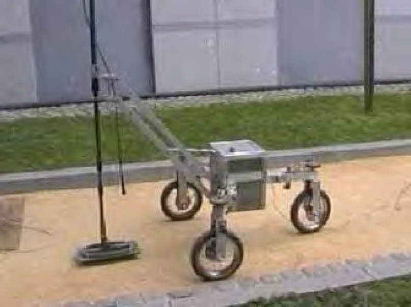
The Tridem equipped with a metal detector mounted on a passive boom.
Regarding the first requirement, we have designed a wheeled robot where each wheel is equipped with a driving and a steering motor. A construction using three wheels insures a permanent contact with the ground without adding any suspension. The repairing requirements lead us to a modular design of our robot: three similar units of driving and steering wheels are fixed on the main triangular frame. The fastening and the connections of the units to the frame should be as simple as possible to allow a quick removal. In case of breakdown or damage a module can be easily replaced by a new one. The defective unit will either be repaired locally or returned to the factory for more important repair, or thrown away if it is badly damaged.
The size of the robot takes into account the dimension and weight of the mine sensors it has to carry (max 10kg). Two electrical motors actuate each wheel: one for the rotation and one for the orientation. In addition, an onboard 32 bits micro-controller controls the three wheels. The Tridem is an omni directional vehicle that has different motion capabilities as illustrated by Fig. 2.
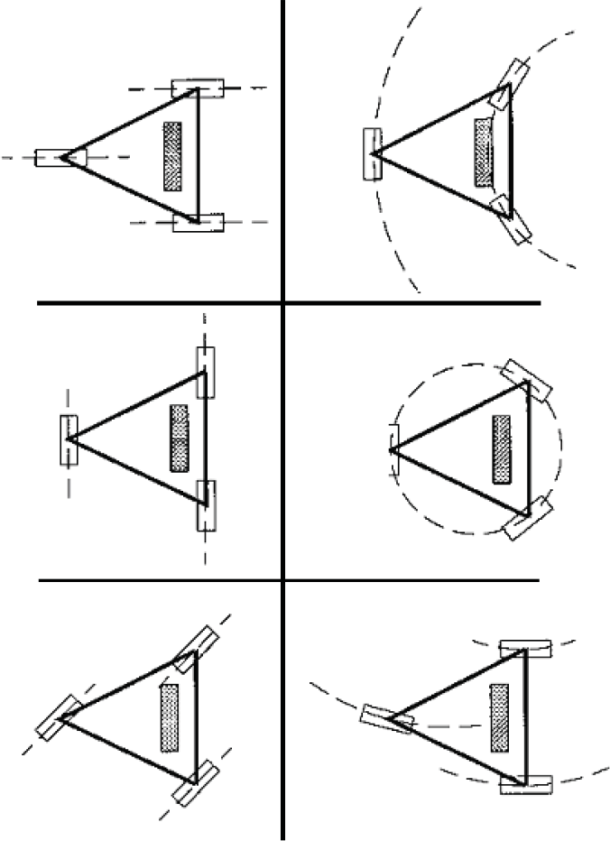
The different motion capabilities of the Tridem
The robot can perform a linear motion in any direction relative to its body; follow circular trajectories in different configuration or turn around its center.
This platform can be used to locate minefields in areas that human deminers have difficulties to reach. A first indoor prototype was built to demonstrate the concept feasibility (Alexandre, Weemaels, Doroftei & Colon, 1998). A second version with more powerful motors and a modified frame has been developed for outdoor trials. It has also been equipped with a spring articulated boom to carry light sensors. Springs are used to compensate the effect of gravity. This mechanism has one degree of freedom that permits the detector to move vertically in order to glide over obstacles. Thanks to this mechanism, the vertical axes of the robot and of the detector are permanently parallel. The Tridem can be controlled by a wired joystick, a remote control or a computer via serial communication. The robot has been tested on dummy minefields and performs well on gravels and grass but not on sand due to the limited size of the tyres. The Tridem can clear small positive and negative obstacles (5 to 10 cm) with the detector still following the ground.
Wheels and tracks have a poor performance in an unstructured environment when faced with a vertical step or a discontinuous surface. Legged robot is a candidate for overcoming this weakness. Legs are sometimes combined with wheels as in the Wheeled project (Guccione S. & Muscato G., 2001).
AMRU4
AMRU4 is a cheap legged-robot that can carry sensors used in humanitarian demining (Metal Detector, Ground Penetrating Radar…). Beside the mobility parts, it is also equipped with a two axis scanning system to move those sensors above the ground surface (Fig. 3). The Operator controls the vehicle by means of a remote computer. It can reach a speed of 0.57 m/s and has a restricted obstacle avoidance capability (10 cm).

The AMRU4 with a metal detector
AMRU4 is a pneumatically actuated Robot with three functional parts. Two frames having each 4 feet slide over each other by means of two double-acting rod less cylinder (Fig. 4). The feet can move up and down and are also actuated by pneumatical cylinders. The orientation is changed by means of a pneumatic rotary drive. The maximum rotation angle is 90° what takes about 1 second (Fig. 5). Two double-acting cylinders and two incremental linear scales are used to realise the scan of the ground surface.

Sliding motion of AMRU4

Rotation principle of AMRU4
In order to lower the cost of the system, the control does not use servo-valves but classical 3/2 valves (Habumuremyi J-C & Baudoin Y., 2000). The pneumatic elements for one leg are showed in Fig. 6.

Pneumatic control schema for one leg
An inclinometer provides pitch and roll angles to the controller. This information is used to maintain the robot horizontally as each leg can be controlled individually. The attitude positioning accuracy is about 5 mm, which is sufficient in this kind of application.
Due to the shape of the feet the robot has only be tested on grass. While pneumatically actuated robots are an alternative to electrical ones, they have additional constraints that make their use on real fields very complicated.
AMRU5 is a hexagonal six-legged electrical robot (Fig. 7). The legs of the robot have been constructed with a compact pantograph mechanism (Fig. 8) that has the following advantages:
Good energy efficiency due to the completely decoupled foot motions. Good rigidity due to the closed loop mechanical structure. Simple control algorithm (inverse kinematics equations are simple).

The six-legged AMRU5

The pantograph mechanism of a leg.
Each leg has 3 degrees of freedom and DC motors attached on each joint have 90W power rating.
Each leg is controlled by a 32 bits micro-controller (Motorola 68332). All controllers are connected to a master controller that coordinates the motion of the legs (classical alternate tripod). To control the robot a hierarchical control with four levels (motivation, body route, kinematics planning -gait planning and leg trajectory- and leg control) is applied. While a classical PID control is enough for the robot to walk in the laboratory, moving in an unstructured environment requires a more advanced controller because of the changing dynamic parameters. For this reason, a Neural-Fuzzy controller that can optimally tune the parameters of the controller has been implemented (Habumuremyi J-C, Baudoin Y. & Kool P., 2004). In this application, we have used an ANFIS architecture (Fig. 9).
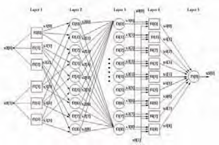
The learning network
At layer 1, every node is adaptive (premise parameters) with a node function that is the membership function. Node output at layer 2 represents the firing strength of a rule. In our application, it is a product of all the incoming signals but can be in general any T-norm operators that perform fuzzy AND function.
At layer 3, a normalised firing strengths is realised by making a ratio of rule's firing strength to the sum of all rule's firing strengths. Nodes at layer 4 are adaptive (consequent parameters) with node function that can be a first-order Sugeno, zero-order Sugeno, Mamdani or Tsukamoto fuzzy model.
The following five steps are required during the development of the controller:
Design an initial zero-order Sugeno Fuzzy Logic controller. Identify the dynamic model of the legs. Estimate the parameters of the dynamic model. Calculate the ideal torque to control the joints and update the parameters of the controller. Design the supervisory control.
Fig. 10 shows the comparison between the proposed adaptive controller and a PD controller when tracking a square signal.
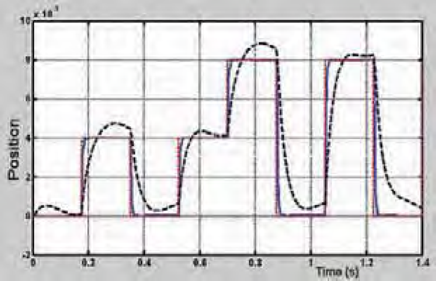
Response of the adaptive controller (solid line) and of the initial controller (dotted line) to a square signal.
We can see on this figure how fast the adaptive controller reaches the set point and how small is the final error.
The Hunter is a caterpillar EOD platform (Fig. 11) that was used by the Belgian Army for anti-terrorism operations. The original manual control system of the vehicle has been interfaced with a micro-controller such that the vehicle can be computer controlled. In order to scan an area and acquire registered data of objects buried in the ground, a scanning system has been developed.

The Hunter platform with the Cartesian scanner
The scanner is actually a Cartesian robot with three degrees of freedom. A DC servomotor coupled with a planetary gear-head actuates each axis. An optical digital encoder is used for position and speed feedback and contact switches have also been placed at the end of each axis. The useful area is 850 by 500 mm and the vertical axis has a travel distance of 500 mm, the repeatability is 1mm. The scanner can be used on both sides of the vehicle and is powered with batteries or with a power supply.
The whole system has a multi-processing architecture that comprises the following components (Fig. 12):
The HMI computer, An embedded computer for data acquisition and communication with the HMI computer, The motion controller (micro-controller), The visual tracking and location computer (section 4).
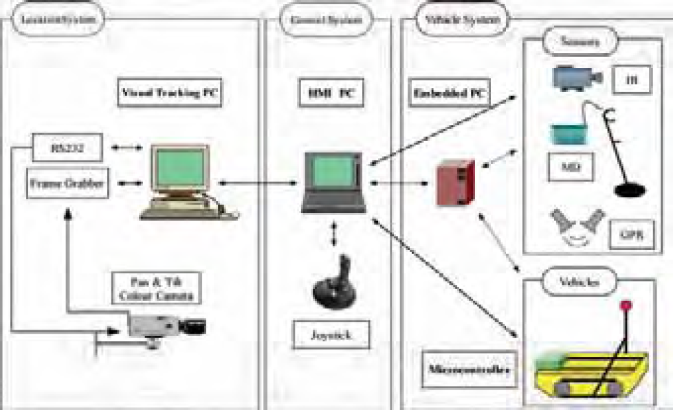
Control architecture of the acquisition system.
The following functions are distributed among the different processing units:
Motion control Processes Synchronisation Data Acquisition
The control architecture comprises two loops: a high level control loop that runs on a Master PC and synchronises high level processes and a low level control loop running on a micro-controller that performs classical control functions (position and speed control). The Master PC is responsible for the synchronisation of the robot motion with the positioning system and for the synchronisation of the scanning with the data acquisition. It sends configuration and trigger commands to the micro-controller trough a serial link and performs the data acquisition.
The role of the Master PC can be played by the HMI PC, when this is directly connected to the vehicle and to the sensors, or by an embedded PC which communicates via an Ethernet radio link with the HMI PC. The HMI application (section 5) manages all control aspects: vehicle and scanning control, communication and data acquisition. A high interactivity and user-friendliness is reached through the use of efficient programming techniques.
The low-level control is realised with a 32-bit micro-controller that communicates through a serial link with the Master PC. The 32-bit micro-controller is very versatile and powerful; it performs the following functions:
It controls the electrical motors of the scanner, It monitors signals coming from contact switches, It generates analogue signals for the tracks of the caterpillar vehicle, It hosts the main communication loop with the Master PC.
The main characteristics of the control methods are given in the remainder of this subsection, more information can be found in (Colon E. & all, 2002). What concerns the Hunter, two control levels can be distinguished: a loop that manages the communication through the serial interface and the motion control functions that are interrupt-based. On the micro-controller, the serial port is polled and a switch-case instruction fires the function corresponding to the received code. Main high level control functions for the Hunter are: set scanning limits, set position, set speeds, move to area limits, start scanning… During the scanning, synchronisation signals are sent to the Master PC to trigger the data acquisition. Two scanning modes are available: a continuous and a discrete one. In the discrete mode, the scanner stops at every step waiting for the end of the data acquisition. The acquisition step can be changed in the set-up dialog box of the HMI.
This system has been tested with different sensors on dummy minefields (section 6).
Colour-based positioning system
This system determines the robot's positions that are used to automatically generate a map of the detections (Hong P., Sahli H., Colon E. and Baudoin Y, 2000). It is able to track a moving target (a coloured ball) by controlling a colour camera mounted on a pan/tilt head, so that the moving object is maintained in the centre of the image (Fig. 13). Furthermore, the size of the target is kept constant by using a motorised zoom and the value of the zoom gives an estimation of the distance. As the orientation of the camera is also known, the ball is completely located in the field.
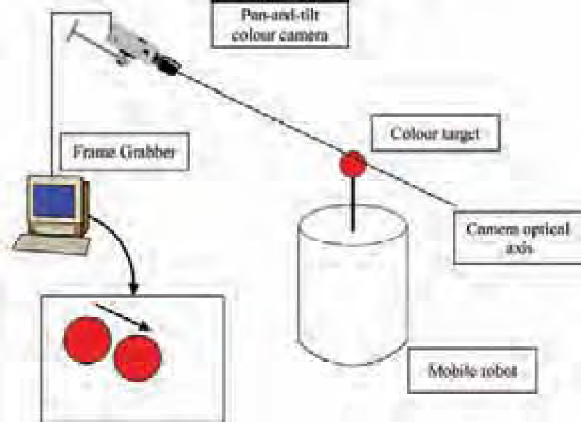
The tracking system principle.
The visual system has four capabilities: target detection, target motion model online identification, camera control for target tracking and target position estimation. In order to minimize the time required for the image target detection, the target is made of elementary features: a simple plain colour spherical object (Fig. 14).

Detected target.
Our approach is directly based upon the physical characteristics of colour reflection. The main problem for the correct interpretation of a camera image is that the measured intensities are function of a large number of parameters and most of them cannot be retrieved in any possible way due to their strong interconnectivity. The colour of an object in the image is therefore more an appearance than a real material property. Nevertheless, colour can be used to identify objects as long as the parameters that influence the formation of the perceived colour are taken into account (Fig. 15). The colour classification process utilizes the distribution of the target colour in the l1-l2-l3-space, a colour space that was originally introduced by Gevers and Smeulders (Gevers T. & Smeulders A.W.M, 1999) as a space that uniquely determines the direction of the triangular colour in the RGB space.
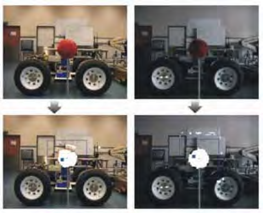
Illustration of the colour constancy in different illumination conditions.
It poses an attractive alternative to the HSI space due to its computational simplicity. The algorithm comprises three phases:
In a learning phase, the algorithm learns the reflection characteristics of the object to be tracked. Small patches of images are accumulated over time while the material in question is subjected to a varying illumination. Having the reflectance spectrum of the target object and the obtained illumining spectra corresponding to different lighting conditions, we can correctly classify newly presented pixels as belonging to the target object or not, while keeping track of newly arising lighting conditions. During the actual tracking phase, the illumination model is continually updated using Bayesian reasoning. In this model updating stage, estimates for new lighting conditions and their corresponding illumining spectra are calculated. It is this procedure that ensures the adaptive nature of the pixel classification process within the general target-tracking program.
The second stage of the detection scheme uses mathematical morphology operators for circular object detection. The camera control exploits the detection in conjunction with an affine fit between 2 consecutive images. After the affine fit has been made, the camera control parameters are estimated. Due to the fact that the perspective projection is a many to one mapping, we designed the servomotor-camera-target system as a time variant system. A two phases' control strategy is therefore implemented. During the first phase (initialisation) the target dynamics is estimated. The second phase consists of a state feedback control strategy. The target depth is estimated by using the appearance similarity between the target and its image. This system updates the target localization in real-time (25 images/second).
A typical precision of 30 cm at distances of 15 m is obtained (Fig. 16), which is enough for this kind of application. Off course, the maximum distance is function of the target size and of the required precision. In order to increase the precision of the location process in varying conditions the coupling of the camera with a laser telemeter is considered.
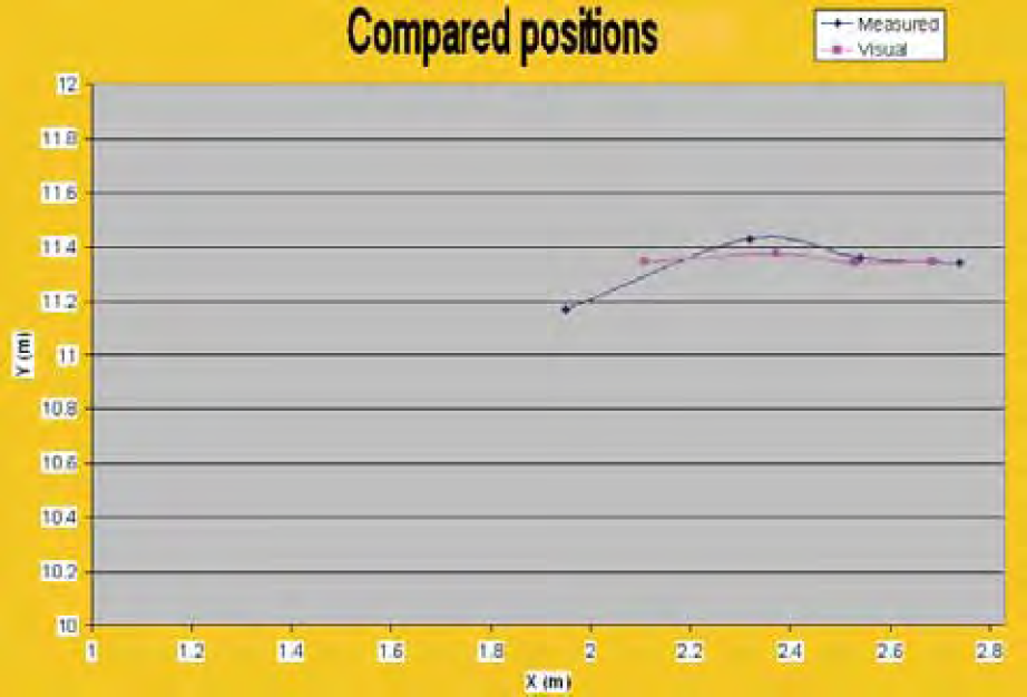
Typical location result.
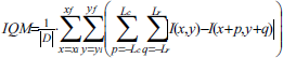
In scanning applications we generally need to keep the sensors above the ground surface at a constant distance. Machine vision can be used for this purpose. The idea is to use two fixed focal length cameras and set them focused on two different distances z1 and z2, as shown in Fig. 17, the ground lying between the two distances (Kundur S., Raviv D. & Kent E., 1997). When the robot or the scanning moves, the ground height changes and the image of one camera becomes clearer and that of the other one becomes further blurred. If the ground moves in the opposite direction the reversed results occur. If we can control the height of the scanning system, we can keep the ground at a specified distance between z1 and z2. In order to evaluate how much an image is blurred we analyse them by using the Image Quality Measure (IQM) that is a kind of high-pass filter and is defined as:

System set-up.
In equation (1), I(x, y) is the intensity at pixel (x, y), xi and xf are the initial and final x -coordinates of the window respectively; yi and yf are the initial and final y -coordinates of the window in the image respectively and Lc and Lr are positive integer constants, which represent the mask size; D is a normalization factor defined as

It can be shown that there exists a distance z0 where the IQM of the two images are equal. Fig. 18 shows the difference between the two IQM's for different textures (carpet, uniform ground and newspaper). The difference is used to control the motion of the camera's and thus to keep them (and the associated sensors) at a constant distance above the ground.

ΔIQM evolution in function of the ground distance
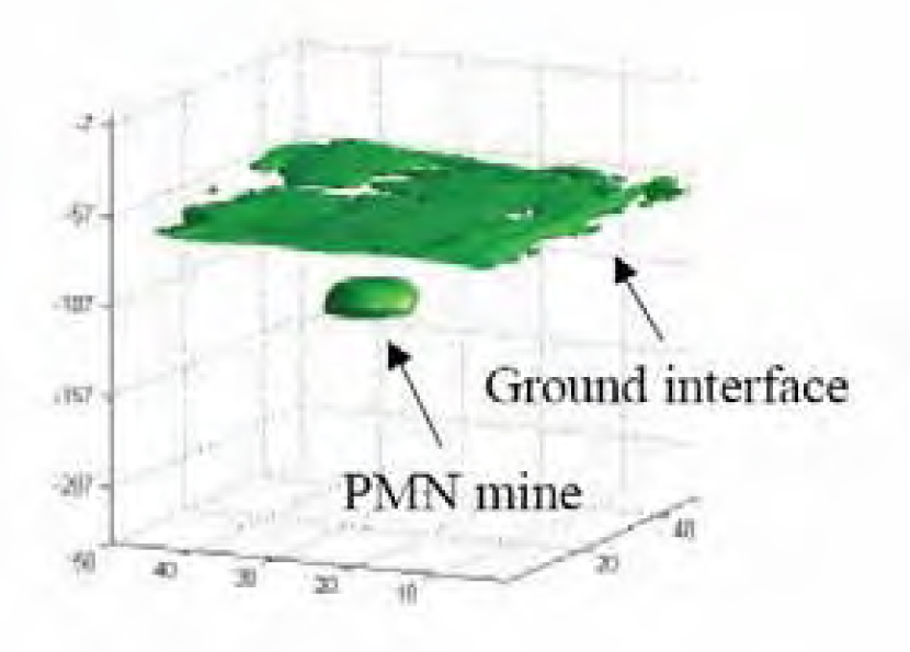
As we know the focal distance of the camera's we can actually obtain the distance from the ground as illustrated by Fig. 19 showing a 3D view of an anti-tank mine lying on the ground.

3D view of an anti-tank mine (right) lying on the ground.
This method is independent of the texture and requires only short calibration operations. The obtained precision is typically 1 mm at 30 cm distance.
The graphical user interface of the control program CoRoDe (Control of Robots for demining) is shown in Fig. 20. This program offers the following functions:
Control of the vehicle, Configuration and control of the scanning system, Configuration of the sensors, Data visualisation, Data archiving, Mapping.

The CoRoDe application User Interface
The main area is devoted to data visualisation. It can alternatively display a map with successive locations of the robot or the sensors' data.
Displayed data can result from two different acquisition methods:
Global acquisition:
Infrared images Video images (used to view and record pictures from the scanned area) Sequential acquisition:
Single values organised as a 2D image (Metal Detector data) One-dimensional data merged into a 3D volume (Ground Penetrating Radar).
The map contains a reference frame and consecutive positions of the robot and scanned areas. The user can switch between either configuration by clicking on a button in the toolbar.
Data acquired during a scan process are saved in two different formats: first as binary data for later processing (double for GPR, double word for MD) and as 8 bits grey scale raw images for direct visualisation. The data acquisition, scanning, location computation and vehicle motion are integrated into a sequence that is controlled by the user with button commands lying in a single toolbar. The interface is simple and intuitive thanks to the use of well-known symbols (VCR-like) and standard colours. In this application, one of the requirements was to let the user keep control of the process; at every moment the user can pause, resume or stop the operations.
It is also essential to provide information during internal processing or timeouts. In this case, sensors' data are drawn on the screen as the scanning progresses. The position of the scanner relative to the maximum positions, the status of the scanning sequence and the main options are also presented to the user and regularly updated. Finally the use of additional communication threads preserves the interaction with the user interface. The software has been satisfactorily used with different sensors on dummy minefields durign data acquisition campaigns.
Three different sensors have been successfully used in the project: a metal detector (MD), a Ground Penetration Radar (GPR) and an infrared camera. A fourth one, a pyrometer, has been tested but abandoned due to unsatisfactory results. The data acquisition process requires different interfaces: the metal detector has a serial interface, the GPR data are read through a GPIB interface of a high speed oscilloscope, the images coming from the infrared camera are captured with a frame grabber (through a cable or a wireless connection). Fig. 21 shows the antennas of the MD and GPR sensors mounted on the Hunter scanner.

The MD and GPR antennas.
Typical results obtained with those sensors are presented hereafter (Baudoin Y., Acheroy M. & Colon E. 2003). A scanning of a close-loop wire with the metal detector is given in Fig. 22. Advanced image processing techniques can recover the original shape from the acquired data.

Close-loop wire (left), the raw metal detector image (centre) and the image after image processing (right).
The following figures illustrate typical results obtained by a systematic scanning of a PMN mine with the Ground Penetrating Radar.

B-scan of the mine (vertical plane)

C-scan of the mine (horizontal plane)
3D view of the mine.
The different systems presented in this paper have been used to acquire data on dummy minefields and have allowed researchers involved in the project HUDEM to develop and improve sensors and data processing algorithms.
From a robotic point-of-view, it has proven difficult to bring prototype vehicles or robots that had not been designed for this purpose on the fields. Most robots lack robustness and ease of use. However, they have been of great benefits in the HUDEM projects and have contributed to its success.
Future work
A new vehicle manufactured by Robosoft has been recently acquired to continue research activities in the Humanitarian Demining domain. The Robudem (Fig. 26) has four wheels that are individually actuated by electrical motors. The two axles are steerable and are actuated by two linear electrical motors via an Ackerman mechanism.

The Robudem on the field.
Current research activities focus on autonomous navigation and distributed control. For this purpose we have developed CoRoBA, which is a distributed multi-robot control framework that uses the CORBA middleware as its low-level communication library (Colon E., Sahli H. & Baudoin Y. 2006). CoRoBa services follow the sensor-processor-actuator scheme; they run in different modes (periodic, synchronized…) and can be remotely managed through a common interface. Services register themselves with a NamingService and are able to localize other services. The communication between services is based on events, namely on the CORBA NotificationService, which provides events filtering and different Quality of Services. Event based communication decouples services and consequently increases the flexibility of the framework. We have also developed a 3D simulator (Fig. 27) that integrates seamlessly with the CoRoBA framework and allows tuning algorithms before real field trials.
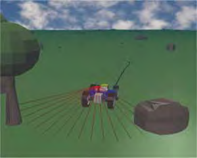
3D simulation of the Robudem with a linear laser sensor.
Behaviour based navigation and Simultaneous Location and Mapping (SLAM) capabilities for single and multi robots are now investigated (Doroftei D., Colon E. & Baudoin Y., 2006).
Footnotes
9. Acknowledgements
The HUDEM project would not have been possible without the contribution of all the searchers involved in the project and without the funding by the Belgian Ministry of Defence and the Secretary for Cooperation and Development.