
Abstract
In bilateral control of tele-manipulation based on a conventional approach, there are deficiencies in stability robustness and manoeuvrability against variations in the dynamics of the master input device and the task environment. In this study, an adaptive four-channel neuro-fuzzy bilateral control scheme is proposed. To evaluate whether the proposed algorithm is a suitable technique for improving the robustness and manoeuvrability of tele-robot implementation, four-channel neuro-fuzzy and classical bilateral control frameworks have been investigated in a simulation experiment. Distinct bilateral control schemes in the form of four-channel intelligent control and the classic form of position–force and position -position have been implemented and compared using a one degree of freedom (DOF) master-slave system. The experimental results show that the application of a four-channel neuro-fuzzy control strategy effectively improves the overall performance.
1. Introduction
Tele-operation and tele-robotic technologies have flourished in the past five decades. Such a wide interest is motivated by the need to provide tele-manipulator systems that enhance a human operator's manipulative capability over distance, in order to execute hazardous applications in hostile environments. However, stability problems can occur when the slave manipulator encounters a high stiffness environment in which large contact forces are fed back to the damped master resulting in oscillatory behaviour. Reduction of either force-compliance gain or force feedback gain is often employed in the tele-operator control loop in an attempt to overcome this problem. However, reducing both gains adversely affects both the manoeuvrability and performance of the tele-manipulator system. Much research has been devoted to the problematic topics of robustness, stability and manoeuvrability.
2. Bilateral Control Architecture
This section provides a summary of bilateral tele-operator architectures. From the literature, it can be seen that several fundamental control schemes are frequently used in tele-operation. A motion and/or force from the master location is transmitted to the control position/velocity and the orientation of the slave manipulator, through a master input device and contact force information from the slave manipulator task space, is fed back to the human operator. The use of reflection force is an important tool for ensuring smooth and efficient tele-operation. A number of researchers have proposed three common types of architecture: basic two-channel bilateral control, basic four-channel bilateral control and modification of the basic architecture.
2.1. Basic two-channel architecture
Position–Position Bilateral Control
Position-position control was the first bilateral control architecture implemented by Goertz in the late 1950s [1] and is illustrated schematically in Figure 1. The force commanded by the operator in the master subsystem and the commanded position in the slave subsystem is proportional to the common position error between the master and slave. On analysing this mode in terms of relative stability, Ow [2] suggested that the position-position mode is the most stable architecture when compared with other two-channel architectures. However, there are some disadvantages that occur when operating in free space. The reaction force/torque is affected by the lag between master and slave position, resulting in “sluggish” movement of the master input device [3]. Other investigations with position-position include the work of Sheridan [4] and Niemeyer et al. [5].
Force–Force Bilateral Control
Typical force–force architecture uses the force error between master and slave subsystems to control reflected force on the master subsystem. The interposition on the slave subsystem is also proportionally controlled by the force error, as depicted in Figure 2.
Because of the presence of noise in the force/torque sensor, the force-force algorithm has the least stability and robustness of two-channel frameworks. However, it can provide a greater manoeuvrability performance [6]. A force framework based on an H∞ optimal controller, designed by Kazerooni et al. [7], was used to overcome the high sensitivity of the force-force system.
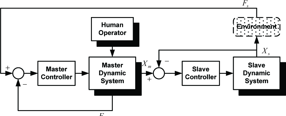
Position-Force Bilateral Control
The position-force control architecture is referred to as a force-reflecting controller, as shown schematically in Figure 3. The force error exerted between the human operator and the interactive force of the slave is used to regulate the reflected force on the master device and applies the master motion to command the interposition on the slave servo subsystem. As it provides satisfactory slave task force tracking force-reflecting architecture is the most common approach in tele-operation applications. However, stability is an issue unless the force/torque feedback from the remote task is significantly attenuated [8, 9].
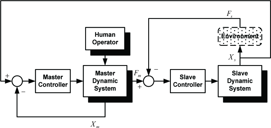
Force–Position Bilateral Control
As shown in Figure 4, the force–position mode uses the same feedback as the position–force system, except that it is reversed. Moreover, the evolving force/torque of the master manipulator is transmitted in the force-position as a motion command to a slave arm, while the position of the slave is scaled and fed back to the master controller. The main benefit of this framework is that the operator can exert a force which is above the physical limit of the human arm force to articulate the slave arm with large force or torque operation, e.g., for cutting or drilling [2].
2.2. Basic four-channel architecture
In 1993, Lawrence [8] proposed a four-channel bilateral control architecture in which the four-channels of the physical information, i.e., the forces and motion of both the master and slave, are exchanged between the two manipulators. A general four-channel bilateral control architecture is illustrated in Figure 5. Consider that the force Fi of the master system, slave system, environment and human operator is related to the position/motion and its impedance. Following the Lawrence analysis without time-delay and disturbance, the four-channel control architecture can provide perfect transparency using the following expressions:

Position-position bilateral control

Force-force bilateral control
Position-force bilateral control
Force-position bilateral control
Additionally, Lawrence proposed that the four-channel architecture could describe a general bilateral framework, in which the two-channel architecture can be represented by one general structure. In this study, the primary objective in the development of a simple one DOF experimental rig was to allow the investigation of an appropriate intelligent control algorithm for improving robustness, stability and transparency of master-slave systems. The incorporation of a four-channel control framework and adaptive neuro-fuzzy control methods will be utilized in the master and slave controller. A comparison of the dynamic response of the one DOF master-slave system using a proportional plus derivative (P+D) and adaptive four-channel control neuro-fuzzy control will be described and discussed in Section 4. In the next section, the single axis test rig will be introduced.
3. Single-Axis Master-Slave System
Figure 6 illustrates the single axis test rig of the master-slave system used in this study.
The master and slave manipulators are directly driven by dc motors with optical encoder position feedback. Strain-gauge bridges are mounted strategically on the handles of both the master and slave to facilitate torque feedback. The dynamic model of the one DOF master-slave tele-operation system comprises the master dynamics, the slave dynamics, slave contact environment and a simple model of the human neuro-muscular system. The master dynamic subsystem includes two coupled bodies: the master handle and a motor coupled by a shaft, as shown in Figure 6. The motion equations of the master handle can be derived as follows:

where Fh, lh, Mh, θh, Jh, Ch and τmo are human operator applied force, length of master handle, mass of master handle, angular position of master handle, moment of inertia of master handle, viscous damping of master handle and coupled torque of master handle respectively. For the dynamically coupled master arm, the torque is transferred via the stiffness of the shaft, yielding the expression:

where Kh is the torsional stiffness of the master shaft and θmh and θmm are the angular positions of the master handle and the master motor shaft respectively. For a permanent magnet dc servomotor torque is proportional to armature current, which can be expressed by:

where τmm, ima and KT are the shaft torque, armature current and torque constant of the master motor, respectively.

where Jmm and Cmm are the moment of inertia and viscous damping of the master motor respectively. The block diagram of the master subsystem is shown in Figure 7. The identification of the slave model is conceptually the same as that of the master arm, which is shown in Figure 8. The dynamic equation of the slave handle can be represented by:

where Khs is the torsional stiffness of the slave motor shaft and θsh and θsm are the angular position of the slave arm and slave motor, respectively.
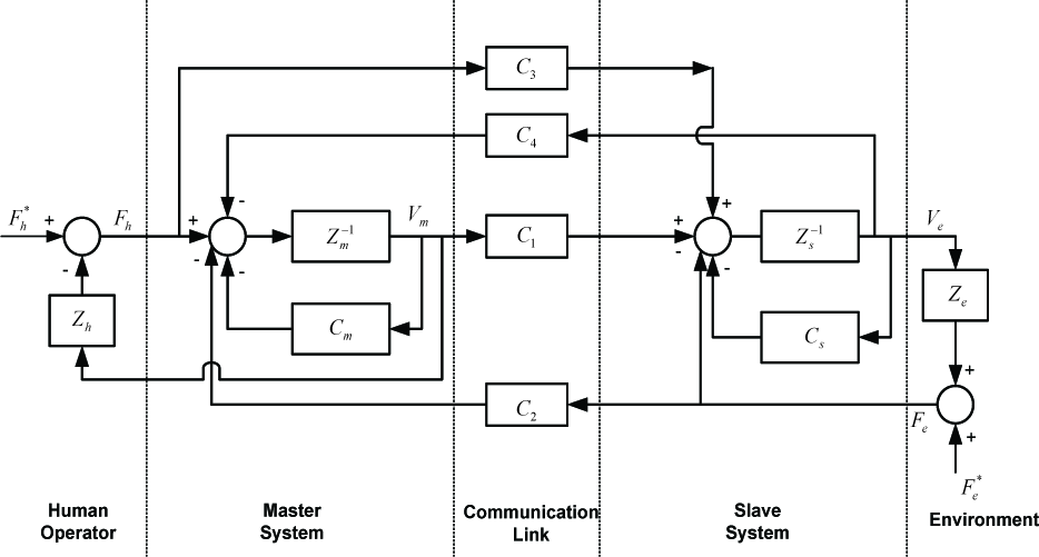
A four-channel bilateral control architecture [8]

The single DOF master- slave tele-operator
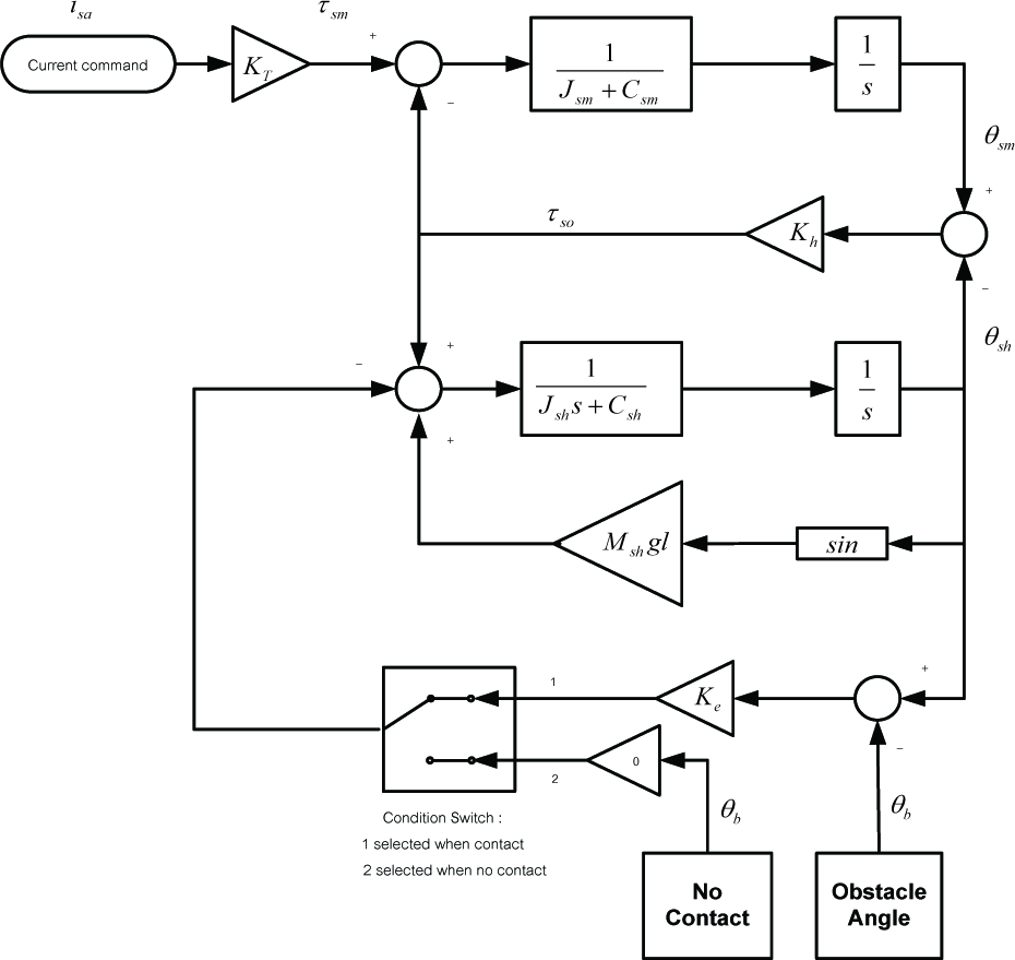
The dynamic equation of the slave handle when it is not in contact with an obstacle is given by:

when θsh< θb
where lh, Mh, θh, Jh, Ch and θb are the length of the slave handle, the mass of the slave handle, the angular position of the slave handle, the moment of inertia of the slave handle, viscous damping of the slave handle and the angular position of the obstacle, respectively. The dynamic equation of the slave handle when in contact the obstacle is:

when θsh ≥ θb and Ke is environment stiffness. An identification mode of the human operator in a simulated “human in the loop system” is usually complicated by the versatility of the human operator. The simple human operator model, which was proposed by McRuer et al. [9], has five components and is shown in Figure 9.
Using experimental data from a human response test, the loop gain, reaction time-delay and neuromuscular lag were employed in the one DOF tele-operator model.
4. Four Chanel Neuro-Fuzzy Control
Neuro-fuzzy controllers have been expressed in many forms and a frequent representation is a multilayer feedforward network [10-12]. There has also been some interest in a self-organizing feature map or unsupervised network as a hybrid system [13, 14]. In neural network representation, it can be easy to visualize and analyse the signal flow through the fuzzy network system. Other researchers have adopted fuzzy and adaptive fuzzy techniques to improve a robot and a robot actuator controller for variable applications [15-19]. Jang [10] introduced the neuro-fuzzy “adaptive network-based fuzzy inference system”, in which the Sugeno fuzzy model was represented as a feed-forward neural network. Based on the Jang fuzzy inference model, a simple neuro-fuzzy system prototype incorporated with a four-channel framework was adopted in this master-slave system research. The hybrid learning algorithm has been employed to adjust two paths of adaptive parameters of the four-channel controller: the forward path and the backward path. In the forward path, a set {pi,qi,ri} is updated by a least mean square estimator. In the backward path, the back-propagation algorithm is performed on the output node and the resulting errors are propagated back to the first node to update the shape of membership functions. Both master and slave controllers have inputs (position error and force error), three input membership functions (Gaussian-shape) and one output with a first order linear function.

The master dynamic subsystem
The slave dynamic subsystem

Human in loop model[9]
On the first layer, every node in the input layer, which is a membership function, is an adaptive node. The output of this node is a matching degree of an input to the corresponding membership functions in the fuzzy set.
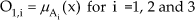
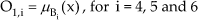
where O1,i is the fuzzy membership grade of a fuzzy set A (force error) and B (rate force error).
On the second layer, each node presents an

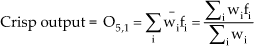
The third layer is also a fixed node. Each node is calculated by weight averaging.

The fourth layer is an adaptive node with each node calculated using Equation 3.7:

where {pi,qi,ri} is a consequent parameter and x and y are the error and the derivative of error inputs, respectively.
The fifth layer is a fixed node and represents the summation of all the outputs of the fourth layer.
There are two sets of parameters for this hybrid neuro-fuzzy system. The first is a first-order linear function in the fourth layer, while the other is a membership function on the first layer. The classic form of such a position-force control in tele-operation using a conventional controller is presently limited by attenuation of the feedback force. Force control for a force-reflecting system is highly non-linear in an unknown or uncertain environment. In this situation, there is a necessity to be able to effectively tune the controller; the proposed four-channel based on a neuro-fuzzy approach was applied to the master-slave controller on the one DOF tele-operation test-bed.
5. Implementation of four-channel neuro-fuzzy
The proposed four-channel based on an adaptive neuro-fuzzy approach was applied to the master force controller on the one DOF tele-operation test-bed, as shown schematically in Figure 11. The function of the learning algorithm is to tune the input and output membership functions for the Sugeno fuzzy inference force controller and consists of a hybrid-learning rule (least mean square combined with back-propagation estimator). Incorporation with hybrid learning was utilized to adjust the output and input parameters for fuzzy logic control. Figure 11 provides an overview of the design procedure used to configure the four-channel based neuro-fuzzy controller in the one DOF system. To establish the initial fuzzy controller, the well-known PID control law concept was utilized to specify the number of input-output MFs and the rule-base table. The fuzzy controller was implemented in the one DOF tele-manipulator system using a Sugeno inference model with four inputs: both position and force error from the master and slave system. Each contained three smooth Gaussian MF variables, i.e., the linguistic values of negative big (
If the performance of the system was not deemed comparable with a conventional control, the architecture should be made more sophisticated and either the number of MFs is increased or the shape of the MFs are changed. After this stage, the fuzzy controller is trained using an artificial neural network to compensate for the undesired features of the control action, which the convention technique cannot cope with. For the neuro-fuzzy implementation in the one DOF system, this tuning process was also programmed and implemented in C on the controller system.

The prototype neuro-fuzzy architecture
6. Experiment Results
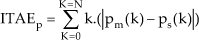
To evaluate any improvement in the tele-manipulator system, the corresponding comparative control experiments were conducted by manually moving the master arm, bringing the slave arm into contact with an obstacle. The position of the obstacle was set at an angle of 0.4 radian with an approximate applied force of 1N applied by the operator. The dynamic response of force and position was investigated. For comparative results, Figures 13 and 14 illustrate the experimental and simulation results of the dynamic response of the classical position-force control framework using a P+D. The position-position scheme (Figures 15 and 16) was also investigated. To evaluate the system performance of the one DOF master-slave system, using both conventional and intelligent four-channel neuro-fuzzy control (Figures 17 and 18), the Integral of Time Absolute Error (ITAE) criterion is used. The ITAE measure is based upon the position and force tracking performance of the one DOF master-slave system, giving a quantitative measure of the performance; the lower the measure, the better the tracking. Equations 14 and 15 give the ITAE equations for the position and force errors, respectively.
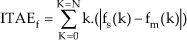
The quantitative performance measurements from ITAE are compiled in Table 1
The quantitative performance measurement from ITAE


Adaptive Four-channel Neuro-fuzzy in master-slave manipulator
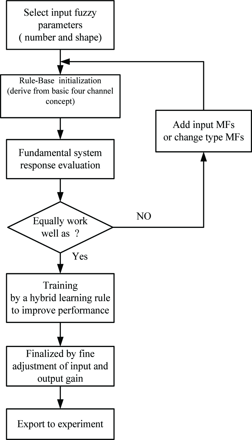
The flow chart of design concept
An assessment of the performance evaluation for system tracking and robustness are provided and then the frameworks of particular interest are discussed. As shown in Table 1 and Figures 17 and 18, the four-channel bilateral control framework based on neuro-fuzzy control can provide excellent results for the overall tracking of the force reflection, while the position-position control framework presents the worst force and position servo performance of all the operating conditions. The position-force control architecture is the most common approach employed in bilateral control applications and can provide robust behaviour. Unfortunately, position-force implemented with conventional control has a very large overshoot (147%) when the slave arm is operated in a hard stiffness environment (Figure 13). However, this problem has been overcome by using the four-channel intelligent controller (Figure 17).

Position and force response based on position-force (experiment)

Position and force response based on position-force (simulation)
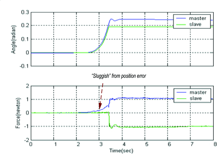
Position and force response based on position-position (experiment)

Position and force response based on position-position scheme (simulation)

Position and force response based on adaptive four-channel neuro-fuzzy (experiment)

Position and force response based on adaptive four-channel neuro-fuzzy (simulation)
Indeed, the characteristics of the position-position control scheme are good stability and robustness, but also defective transparency. Low oscillation can be achieved with the position-position framework. However, as the system behaves “sluggishly,” the resulting force error between master and slave subsystem is high (ITAE approximately 4450.22). The neuro-fuzzy controller will compensate for this non-linear sluggishness, because the controller designed in this case study applies an intelligent non-linear control algorithm. Learning rules are utilized to tune the MFs of the fuzzy controller. This improves the fidelity of the force flection and stability under such conditions. Figures 17 and 18 demonstrate that the undesirable “sluggish” force/torque behaviour in free space movement was effectively suppressed and overshoot under the given high stiffness environment was improved by the four-channel framework incorporated with the neuro-fuzzy algorithm. When implemented with adaptive neuro-fuzzy four-channel control, tele-operation manoeuvrability can be improved under the same criteria, as evident in the system response and can provide excellent results for satisfactory summation of position and force tracking error (ITAE 3720.88), as shown in Table 1.
7. Conclusion
The bilateral control schemes in the form of intelligent four-channel neuro-fuzzy control and conventional control have been implemented and compared using both experimentation and simulation on a one DOF master-slave rig. The adaptive model four-channel neuro–fuzzy controller has proven to be capable of compensating non-linear systems and providing better overall performance than the conventional framework.