
Abstract
The present work focuses on the computational modelling of fluid flow in a mixing stirred reactor to describe the flow pattern in two-dimensional (2D) detail, which can be useful for optimizing the parameters of electroplating for the production of a uniform film on metallic particles in a stirred electrolytic cell.
The results of modelling and simulation show that the electrolytic cell geometry and the presence of a solid electrode affect the streamline distribution. The most important parameter affecting the fluid flow is not just the position but also the size of the stirrer as well. It is concluded that the “high cell” with the “big stirrer” can be used for the electroplating of iron micro-and nanoparticles in the presence of the cylindrical electrode.
1. Introduction
A fluidized bed electrolyzer was first described in 1966. A few routine applications can be found, for example, in fuel cells, organic electrosynthesis and metal electrowinning from very dilute solutions [1]. Recently, the use of fluidized bed electrolysis has increased (see [2–3]) and a popular application of fluidized bed reactors is both the removal and recovery of heavy metals from aqueous solutions by bio-sorption and electrolysis [4–5].
A fluidized bed electrode consists of solid metalized or metallic particles, dispersed by a vertical flow of electrolytes [6] or by a stirring of the electrolyte solution [7]. With a sufficiently high fluid velocity, the particles are suspended by a fluid and the whole bed of particles becomes mobile. The dispersed particles intermittently come into contact with the solid electrode so as to be charged and thereby plated with a metallic layer. This packed-bed reactor system possesses various advantages and in particular a larger reactional area and significantly enhanced mass transport.
Several authors have studied and modelled details of the charge transport [8–11] and mass transfer in systems with vertical electrolyte flows [1, 12]. The electronic conduction within the fluidized bed electrode has also been discussed and different mechanisms have been proposed. The convective transport of charged particles accompanied by charge sharing collisions with other particles is the most frequently accepted explanation for the enhanced electron transport [1, 10–13].
Several studies on the fluidization of agglomerates of nanoparticles have been carried out that include conventional fluidization and externally-assisted fluidization in order to enhance the dynamics of the powder in the fluidized bed [14–16]. It has been found that the nanoparticles form fractal agglomerates and that the size and porosity of the agglomerates affect the nature of the fluidization.
Fundamental investigations have been done on circulating fluidized beds of zinc particles in order to understand the interactions between the moving particles [10, 11, and 17]. From both impedance measurements and the spectral analysis of the potential fluctuations, the time constant of the discharge of the particles previously charged during collisions with the current feeder was determined. Moreover, it was shown that only continuous chains of particles from the current feeder to the probe carried charge in this electrolyzer.
In order to modify a base metal material in powder metallurgy, several procedures can be adopted. The electrolytic fluidized bed coating of particulate substrate materials is one of the processes that provide for a high homogeneity of the final product. Therefore, it could achieve great importance in powder metallurgy. The interactions between the dispersed powder particles and the current feeder, and the interaction between the particles in the fluidized bed near the electrode surface, significantly affect the plating efficiency and the quality of the deposited coatings. The modelling of the particle path and contact time with the solid current feeder facilitate the optimization of the cell geometry, dimension, shape and position of the electrodes and the stirrer and thereby maximize the efficiency of the powder material electroplating.
The optimization of this type of electrochemical reactor depends upon the hydrodynamic conditions, the cell geometry, the physicochemical properties of the electrolyte, and also upon the electrochemical reactions involved. In addition, there is a lack of knowledge about the working principles of the mixing stirred electrolyzers. Thus, our purposes was to better understand the relationships between the variables of cell geometry, the stirrer characteristics, the presence of a solid electrode and the response of the fluid flow, as well as to optimize the operating conditions by using the Chemical Engineering Module of the COMSOL Multiphysics 3.2 software. In our previous study [18], the basic fluid-dynamic three-dimensional (3D) models were developed to help predict the influence of the operating parameters on the fluid flow for the mixing of the stirred electrolytic cell. The present paper is devoted to a comparative analysis of simple models representing 2D simulations of fluid flow patterns in an electrochemical reactor. An experimental verification of the selected optimal experimental cell arrangement was performed.
The main argument for changing to the 2D geometry with circular symmetry came from considerations of electrochemical efficiency. The particle coating was much more efficient when the planar electrode was extended to cover the entire circular periphery of the cylindrical vessel. This leads to the circular symmetry and also causes a minimum deviation of the flow pattern from a laminar one, which is the optimum for the intended homogeneous particle coating.
The results of the computational modelling of fluid flow in a mixing stirred reactor are useful, which is essential in powder metallurgy.
Regarding the contribution of the modelling presented in this work in the field of nanotechnology, it mainly concerns its potential application for optimizing the parameters of electroplating and for producing a uniform nano-sized film on metallic nanoparticles in a stirred electrolytic cell. Iron particles have been used in various phases, such as the sintered phase and the dispersed phase, depending upon the given requirements. When the grain sizes move into the nanoscale, the metals become stronger and harder. This makes nanocrystalline materials very interesting from a mechanics point of view. Conductive nano-sized coatings deposited onto the particle surfaces should greatly facilitate the rearrangement of the particles and the diffusion of the components during powder metallurgy processing (the compaction and the sintering). When the amount of the coating layer is controlled at a nano-sized level and distributed homogeneously, it should avoid performance degradation while introducing new functionalities, such as electrical conductivity, hardness and magnetism. Consequently, a coated nanopowder material is suitable for more applications (e.g., self-lubricating, self-repairing, anti-friction and anti-wear film coatings).
2. Mathematical Formulation
The basic theoretical features, the problem formulation and the hydrodynamic conditions for 3D axisymmetric models of a mixing stirred electrolyzer were described in the previous paper [18]. Here, the formulation was extended to a 2D framework.
Since the cylindrical electrolytic cell-in the absence of a rectangular electrode-is rotationally symmetric for the 3D versions of the axisymmetric models (3D models), they can be reduced to the 2D versions of the axisymmetric models (2D models), as can be seen in Figure 1.
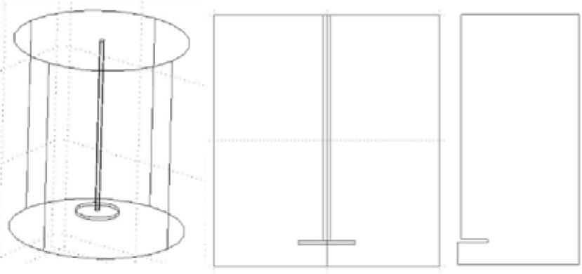
The original 3D geometry reduced to 2D and 2D axisymmetric geometry.
To simulate the fluid flow in a 2D axisymmetric cell, the 2D Incompressible Navier-Stokes application mode in the above-mentioned Chemical Engineering Module was used. The boundary conditions are illustrated in Figure 2. The simulation was computed using the Navier-Stokes equation by analogy with the 3D simulations.
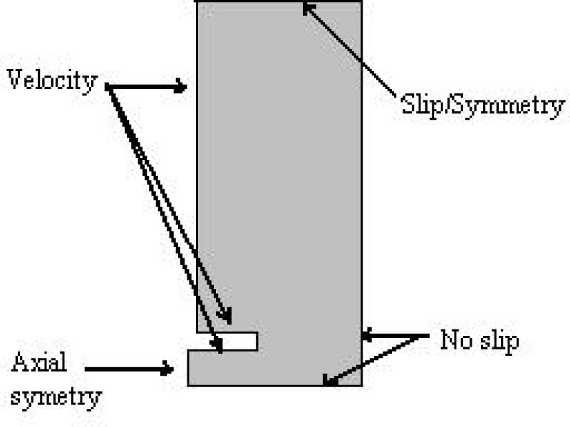
Boundary conditions of the 2D axisymmetric model.
Due to the fact that the geometry of the rotating stirrer containing the electrolytic cell is rotationally symmetric, it can be modelled as a 2D cross-section. However, the velocities in the angular direction differ from zero (as shown in Figure 2) and all the three velocity components (namely the radial, axial and rotational velocities) were necessary to model.
The origin of the rectangular Cartesian coordinate system was again in the centre of the base surface in the electrolytic cell. This is situated on the bottom-left corner (see the scheme in Figure 2). In 2D axisymmetric geometry, the x-axis represents r (i.e., the radial direction) and the y-axis represents z (i.e., the height coordinate).
The same boundary conditions which are described for the 3D modelling will also hold in the 2D modelling. Therefore, the following boundary conditions were considered.
The velocity boundary condition for the stirrer is prescribed as:

where
At the electrolytic cell surface (bottom), a no-slip boundary condition is applied. This means that the fluid velocity is equal to the boundary velocity, which is zero. Therefore, all of the components of the velocity vector are to be:

Furthermore, the slip/symmetry boundary conditions at the top of the cylindrical electrolytic cell represent a free surface. This condition allows the flow in the axial and rotational directions only:

In addition, an axial symmetry boundary condition was added. This boundary condition assumes that there is motion in the tangential direction only and that no fluid flow occurs in the normal direction (i.e. the radial velocity u is equal to zero). This is shown as follows:

3. Experimental Details
The electrochemical deposition of Ni coatings onto iron powder was studied using an electrochemical cell with a fluidized bed cathode. A polished cylindrical stainless steel cathode with an exposed surface area of 51.8 cm2 was used as a working electrode. The anode was a nickel sheet. The electrolytic cell with separated anodic and cathodic compartments was used for electrolysis. The anodic and cathodic compartments were connected with a diaphragm, which hinders the dissolution of iron powder particles at the anode but also enables the transport of ions between the anodic and cathodic compartments. The suspension formed by 5 g of Fe powder and 150 ml of electrolyte in the cathodic compartment was held in a fluidized state by intensive circular stirring (600 rpm) during galvanostatic electrolysis using a potentiostat (A LPS 302, AMREL American Reliance Inc., USA) for 30 min with a constant current intensity 0.5 A. Two different stirrers of diameter 3 cm (“small stirrer”) and 5 cm (“big stirrer”) were used in accordance with the presented model.
The water-atomized iron powder (Höganäs, ASC 100.29 grade) was used as a starting material for electrolytic coating by nickel. The iron powder was chemically activated by etching in reducing agent (10% solution of hydrazine dihydrochloride) for 5 min before the electrolysis. The plating electrolyte of pH 2 consisted of 1.2 mol/l Ni-SO4.7H2O, 0.6 mol/1 NaCl and 0.6 mol/1 H3BO3.
The content of the Ni deposited was determined after dissolution in nitric acid by atomic absorption spectrometry (AAS, PERKIN-ELMER 420).
A microstructural analysis of cross-sections of the coated iron particles was carried out using a scanning electron microscope (SEM, Tesla BS 340, Czech Republic).
4. Results and Discussion
4.1 Modelling of the mass flow in a mixing stirred reactor in the absence of a solid electrode
Figure 3 shows the fluid flow profile of the model presented in this work in comparison with the model presented in the previous paper [18]. As both the models are generated with the same input quantities for the electrolytic cell without a rectangular electrode, the 2D model (Figure 3(b)) is the reduced form of the 3D one (Figure 3(a)), as was mentioned above.

Comparison between (a) 3D and (b) 2D simulations performed at the same conditions.
By comparing these figures, one can see that the distribution of the fluid velocity, which is shown in both numerical values and vectorial form (the colouring as well as the position), is slightly similar. Therefore, the fluid flow profile between the 2D and 3D models probably does not differ greatly. Based on this, the simplification of the fluid flow simulation of 3D into 2D may be considered.
4.2 Modelling of the mass flow in a mixing stirred reactor in the presence of a cylindrical electrode
The modelling of the fluid flow for the reactor containing the solid electrode is very interesting in relation to the electroplating of the dispersed iron powder with a metal or polymer coating. The use of a stirred reactor should ensure a higher probability of effective contacts of the dispersed powder particles with the compact electrode. Since the whole system is rotationally symmetric, it allows the carrying out of 2D axisymmetric modelling.
The data presented in Figures 4 and 5 reveal that the stirrer size has an important impact on the fluid flow in this system. At given conditions-i.e., in the “high cell” (the so-called “high cell” because of the ratio of the radius to the height of this cell is 1:2 – in the same way as in our former work [18])-with the cylindrical electrode and at the same rotation speed of the stirrer (with angular velocity ω=100), the flow pattern depends upon the size of rotating stirrer, which was varied from 0.005 to 0.01.

Surface plot for the “high cell” in the presence of cylindrical electrode with (a) the “small stirrer”; (b) the “big stirrer” at applied angular velocity ω=100.

Streamline plot for the “high cell” in the presence of a cylindrical electrode with (a) the “small stirrer”, (b) the “big stirrer” at an applied angular velocity ω=100.
The Arrow plots for the “high cell” in the presence of the cylindrical electrode with the “small stirrer” and the “big stirrer” are presented in Figure 6. The red arrows are used to provide detailed information about the fluid flow on a small area. The arrows have different sizes and directions as a function of the local flow velocity.

Arrow plot for the “high cell” in the presence of a cylindrical electrode with (a) the “small stirrer”, (b) the “big stirrer” at applied angular velocity ω=100.
By comparing the plots of the flow modelling results obtained using the 2D version of axisymmetric model in Figures 4, 5, and 6, a different fluid velocity profile in the axial direction can be found. As depicted in these figures, both the size of the stirrer and the presence of the cylindrical electrode affect the streamline distribution in the electrolytic cell. As shown in Figure 4, the predicted flow velocity obtained through simulation is higher near to the compact electrode in the case of the “big stirrer”. The radius of the stirrer was 0.01. In addition, the calculated velocity profile for this situation can be observed from the Arrow plot (Figure 6). In the case of the “high cell” with the “big stirrer”, the detail of the received velocity streamlines is represented by bigger red arrows close to the solid electrode, as shown in Figure 6(b). Consequently, the effective contacts would be expected in this electrolytic cell during iron powder dispersion (see Figures 4(b)–6(b)).
4.3 Experimental verification
In order to verify the findings of the presented model, a set of experiments for the “high cell” the presence of a cylindrical the “small stirrer” and the “big stirrer” at speed of the stirrer were performed.
The experimentally obtained amount of the metal coating on the powder particles was used for the evaluation of the coating process. The effect of the stirrer diameter on the amount and quality of the deposited nickel coating layer was studied. The amount of electrodeposited nickel in the coated particles was 9.1 wt.% and 12.5 wt.% for the “small stirrer” and the “big stirrer”, respectively. The metal deposition on the solid cathode is the main side reaction that lowers the amount of electrochemically deposited metal on the particles. The electrodeposition of metals on the solid cathode was of no interest and, therefore, the amount of metal coating on the solid cathode was not determined. The other side reactions-such as hydrogen evolution-also contributed to the decrease of the current efficiency of the particles electroplating.
Figure 7 shows the cross-sections of a Fe particle coated with an electrodeposited nickel layer using a stirrer of a diameter 3 cm (Figure 7(a)) and 5 cm (Figure 7(b)). It is evident that both coating layers are of good-quality, continuous and adherent; however, a thicker, more uniform and homogeneous nickel layer was obtained by the exploitation of the “big stirrer” (Figure 7(b)). Moreover, each iron particle was coated with a nickel layer, while some uncoated particles were observed when using the “small stirrer” (Figure 7(a)). These micrographs, together with nickel content in the coated particles, indicate that the higher flow velocity in the vicinity of the compact electrode in the case of “big stirrer” ensures an adequate number of efficient contacts to cover the whole of the iron particle's surface with a uniform nickel layer. Furthermore, the predicted effect of the stirrer diameter on the electroplating efficiency was proven. Hence, the mathematical model can be used for large parametrical studies of electrochemical systems. Various parameters can be tested and arrangements suitable for experimental study can then be selected.
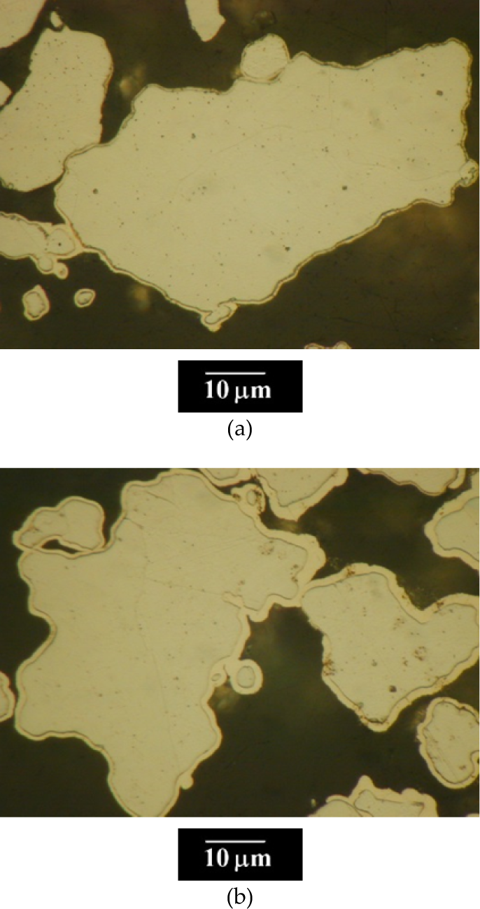
Micrograph of a cross-section of a Fe particle coated with a nickel layer obtained by electrodeposition using a stirrer of a diameter 3 cm (a) and 5 cm (b).
5. Conclusions
The models presented here are 2D simulations that describe the fluid flow in an electrolytic cell both with and without a compact electrode. The effects of these parameters can be simply studied by means of these simulations.
Two types of solid electrodes could be used throughout the electroplating – namely, the rectangular and cylindrical cathode, respectively. The cylindrical electrode is to be considered for the metal powder electroplating in order to ensure an increase of the effective contacts of dispersed powder and micro-and nanoparticles with the compact electrode.
This paper provides the general theoretical treatment for the fluid-dynamic characteristics of a mixing stirred reactor. The setting-up of a real reactor in accordance with the obtained results have led to an increase in coating efficiency. The knowledge of the particle path and contact time with the solid current feeder allow us to optimize the reaction cell geometry, dimension and shape, as well as the position of the electrodes and the stirrer, and-thereby-to maximize the efficiency of the powder material coating process. On account of this, the theoretical treatment is first developed for the particular case of a mixing stirred reactor. For this reason, the further investigation of these models is necessary. Obviously, the next step might be to change the shape of the glass stirrer (to be more similar to the real one); additionally, there is the investigation of the flow pattern as a function of changing dynamic viscosity and fluid density; furthermore, iron powder particles may be added to the electrochemical system.
The experimental verification of the mathematical model acknowledged its applicability in order to estimate the effect of various parameters on the flow distribution and, thereby, on the coating efficiency.
The results of the computational modelling of the fluid flow in the mixing stirred reactor are useful for optimizing the parameters of electroplating in producing a uniform nano-sized film on metallic micro-and nanoparticles in a stirred electrolytic cell, which is essential in powder metallurgy.
Footnotes
6. Acknowledgements
This project was financed by Grant VEGA 1/0211/12 of the Slovak Scientific Grant Agency and Project APVV-0677-11 of the Slovak Research and Development Agency. We would like to express our thanks to the Inorganic and Analytic Institute of the University of Münster in Germany in using of the Chemical Engineering Module of the COMSOL Multiphysics 3.2 software.