
Abstract
A generic method for automatic shape recognition on two-dimensional contours, particularly used for recognizing punch shapes for progressive dies, is presented in this article. In this work, shapes of two-dimensional contours are defined by shape templates using a sequence of symbols, lists, and numbers, and their definitions are stored in a specially designed database for the minimum number of shape definitions to be retrieved during shape recognition for optimal computational efficiency. When a contour is input from a computer-aided design system for shape recognition, the computer-aided design data are translated into shape components and input to the shape recognition device. Upon successful recognition of a shape, the shape code will be composed and its dimensional values will be extracted. Standard or special punch purchase code may be created automatically through this method.
Introduction
Progressive dies for manufacturing sheet metal parts in mass production have been widely applied in various industries. With progressive dies complex parts can be produced with high precision and high productivity for piercing, notching, cutoff, blanking, lancing, bending, drawing, embossing, coining, trimming, and other miscellaneous forming operations being performed in a single setup. Due to their complexity, planning and design of progressive dies can be a very demanding work if general-purpose computer-aided design (CAD) systems are employed. Special-purpose CAD systems with built-in knowledge of progressive dies and productivity design tools will help the designers reduce their design time and errors significantly.
Among other tasks, planning and design piercing punches are unavoidable in almost every progressive die. Therefore, there is a need to sort piercing punch shapes from the strip layout drawing to build a punch database. The automatic sorting of two-dimensional (2D) drawing contours may be based on a shape recognition technique. Punch shapes are classified as “standard punches,”“special punches,” and “in-house” machined punches. The terms of standard punches and special punches can follow an industrial specification like Misumi catalog. 1 These two groups of punches are defined in the catalog and can be ordered from standard punch vendors by passing them the punch codes, whereas the in-house machined punches are normally manufactured in the workshop by adopting wire-cut operations.
Previous work
Research and developing efforts toward developing intelligent CAD systems for progressive dies have been made in various areas, such as sheet metal folding and unfolding, manufacturability verification, strip layout design, and die structure design. Punch shape recognition, which is our target in this research project, contributes to the die structure design module. Shape recognition in general is a hot area for researchers and developers, and great efforts have been made in the past on image processing and machine vision applications. For CAD applications, some specific systems have been developed to capture CAD user’s intention during graphical input stage to understand the shapes of the input. For example, in Bozinovic and Pagallo, 2 a patent was filed. The classic method for shape or diagram recognition may be the syntactic analysis approach. 3 In this approach, domain knowledge is represented by a grammar, which consists of a start symbol and a set of rewrite rules. Depending on the formalism, a rewrite rule replaces one substring by another, one subtree by another, or one subgraph by another. Henderson and Davis 4 have done typical work in syntactic pattern recognition to recognize 2D shapes. However, in their work, a contour is discretized into a number of straight lines, and it is thus not suitable for our concerned problem, contours composed of both lines and arcs. Plex-grammars have been used to interpret dimensions in engineering drawings. Gmür and Bunke 5 made attempts to recognize three-dimensional (3D) solid models. Aiming at recognizing rotational part contours that are represented by a chain of straight lines and curve segments, Jakubowski and Kasprzak 6 assigned 32 characterological descriptions for the segments. The contours are then described by a list of alphabets. Local grammar is utilized to parse the representations. A similar scheme implemented by Staley et al. 7 can recognizes holes. A list of octal alphabets specifies the contour, while the geometrical data specify the length and angle of straight and chamfered edges. Considering four-sided figures only, Peters 8 worked on a system that integrates the neural net concept with feature recognition techniques. A similar work done by Chan and Lee 9 interprets 2D features and the system is implemented in AutoCAD to recognize features from a drawing interactively. Parry-Barwick and Bowyer 10 worked on a method based on multi-dimensional set-theoretic, translation, and rotation operators and template matching for feature recognition instead of direct template matching. The method is suitable for recognizing local characteristics of a 2D contour. Meeran and Taib 11 presented a fine work for recognizing machining features from 2D drawings.
A review of the existing methods of shape recognition indicates that no methodology is powerful and flexible enough to be a generic one for recognizing the overall shape of a piecewise smooth simple closed contour that consists of any number of lines and arcs. For example, Staley et al. 7 used eight pattern primitives of recognizer for straight lines in extracting feature information from a solid geometric database, while Jakubowski and Kasprzak 6 employed 16 pattern primitives for straight lines and 16 for arc segments. They may be good enough for a chosen application, for example, in recognizing rotary machined parts, but they failed for many punch shapes encountered in CAD applications for progressive dies. There is a need for a more generic method that can describe our concerned shape.
In the present problem, Cheok et al.12–14 implemented a module in a CAD system for recognizing the overall shapes of 2D contours. However, they did not present a generic method but a heuristic approach for recognizing about 30 shapes that are related to special punch shapes. Cheok et al. 15 also proposed the skeleton retrieving method to determine the punch shape; the system is made based on the medial-axis technique. Similar to Cheok et al., 15 Ghatrehnaby and Arezoo16–19 also used the medial-axis technique to retrieve punch shapes in case of progressive dies. Ismail and colleagues20–22 proposed a mathematical technique based on vector-to-vector coding. The system was built for progressive dies and coded with C++. Hussein and Kumar 23 made an attempt to develop a computer algorithm to retrieve sheet metal part of similar shapes and sizes from a database of about 2000 parts. In the endeavor, they used lower left and upper right vertex points, width and height, geometric center, and area for the representation of part geometric characteristics instead of true shapes and dimensions of parts due to the unavailable techniques for shape recognition in CAD applications. Jia et al.24,25 studied the classification of plate holes and punches of progressive die design according to their structural types and relationships between the correlating parts and the plate holes and described an automated hole design system for progressive dies. Kim and Choi 26 suggested a guideline to classify problems related to nail clipper progressive die punches for Three Seven, Inc.
Two of the widely used CAD systems in die design are known as SMCAD 27 and ComposerCAD, which were developed on the AutoCAD platform, for progressive dies, compound dies, and stand-alone dies. The work reported here is part of the efforts for developing those CAD systems.
Although shape recognition is a hot area for researchers and developers, in the area of applications related to CAD, not enough efforts have been made leading to generic method of recognizing 2D shapes in a CAD environment. In the following sections, the current system for modeling and recognizing shapes of contours will be presented along with the results and discussion.
The shape parameters of a closed 2D contour
Contours that we deal within our scope of research must meet the following conditions:
They consist of straight lines and arcs with the end point of one segment being coincident with the start one of the next.
They must be closed, that is, the start point of the first segment is in coincidence with the end point of the last segment.
A segment of one contour must not intersect itself with another segment of the same contour, that is, the contour forms a single region.
This type of curve, of concern here, is widely found in CAD applications and their shapes can normally be defined and controlled with a number of dimensional parameters. In this sense, we can call these contours simple parametric contours.
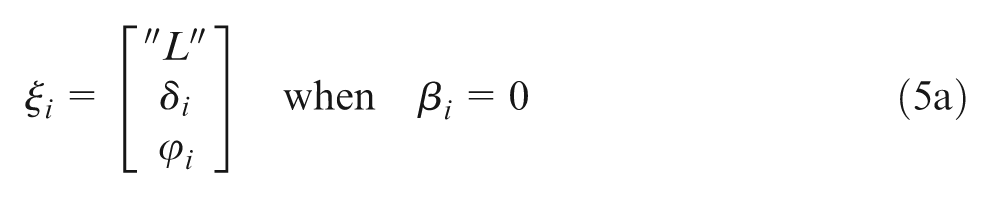
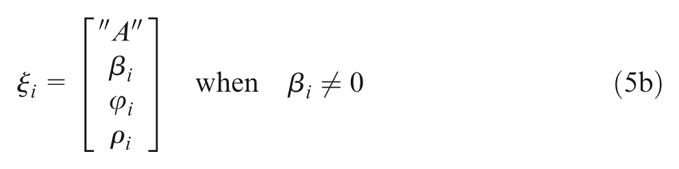
For practical application reasons, we only consider the contour of the shape and define the shape of such a contour by the following formulae
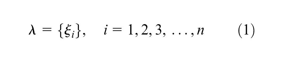
where ξi is the shape component of segment i, which has a format of
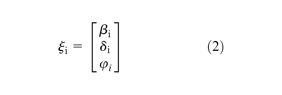
where βi
is the bulge factor of the ith segment, δi
the linear dimension of the segment, and
The bulge factor has been adopted in some CAD systems for defining a “polyline” or “lightweight Polyline.” It is defined to be the ratio of the height of the arc to the chord and the value is related to the included angle of the arc by
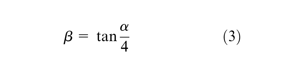
where
The linear dimension of the segment, δ, will be either the length for a line or the radius of an arc.
The rotational angle, φ, has a range from 0 to 2π, starting from the tangential direction of the current segment at its end vertex to that of the next segment at its start vertex while the two vertexes must be coincident with each other.
These parameters of a shape component in equation (2) are invariant when the curve is translated, rotated, or scaled.
In theory, therefore, the shape of a 2D contour can be defined by equation (1), with the start segment being any one. In the implementation of the shape recognition system, we tried to choose a special segment so that the computational time is minimized. The shape definition is independent of the start segment for the reasoning device will recognize the shape by taking each segment as the start one in turn in the worst case.
The system’s implementation
The shape recognition system consists of a preprocessor for extracting shape data, a knowledge base for storing the knowledge of shapes, a shape recognizing device for reasoning, and a post-processor for generating dimensions of the contour. The shape recognition module is also integrated with an auto-dimensioning module for the creation of traditional linear, chamfer, radius dimensions for hundreds of parametric shapes.
The preprocessor
This type of contour may be created in a CAD system by a closed polyline or lightweight polyline entity, as in AutoCAD system. For a profile created by separate lines and arcs, they can be converted into a polyline.
The preprocessor of the system will read in the polyline and analyze its geometric data, making sure it is a closed polyline. The system will stop when it is not found closed. Then, it will check for its direction. 15 If the curve is in the clockwise or negative direction, the extracted data need to be properly reversed and processed. Finally, a list of vertexes and bulge factors is generated for computing the shape data
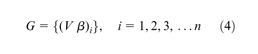
where V is the vertex and β is the bulge factor. From this, the shape value of equation (1) may be generated. In our implementation, we choose a slightly different format of shape data as in equation (2), for convenience in data handling
or
The knowledge representation of shape
The shape code
A shape code is designed to distinguish one shape from another. In addition, it is used for indexing shapes and optimizing the computational algorithm. The shape code consists of a string with six digits. The first two indicate the number of segments, the second two stand for the number of lines to form the contour, and the last two for a serial number for the same category of contours.
For a code 040402, it means that the contour has four segments, all the four segments are lines, and it is the second shape in the knowledge base for its type. Likewise, a code 080604 means that the contour has eight segments, six of them are lines, two of them are arcs, and the shape definition is stored in the knowledge base in the fourth position under the same shape category.
The shape description
Shown in Figure 1 are four typical 2D contours. Six digits are used for the shape code below each.
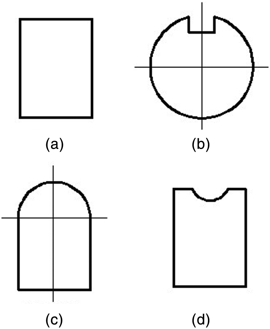
Typical 2D contours: (a) 040402, (b) 040304, (c) 040301, and (d) 060504.
To understand how a shape is described, we take the shape in Figure 1(a), as again shown in Figure 2 where each segment is assigned a number. Using plain English language, we can define a rectangle by the following constraints and rules:
Segment 1 is a line, and it is rotated 90° from segment 1 to segment 2.
Segment 2 is line, and it is rotated 90° from segment 2 to segment 3.
Segment 3 is a line, and it is rotated 90° from segment 3 to segment 4, and the length of segment 3 is equal to that of segment 1.
Segment 4 is a line, and it is rotated 90° from segment 4 to segment 1, and the length of segment 4 is equal to that of segment 2.
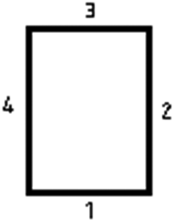
A rectangular shape and its segments.
Since the total rotational angle is a multiplication of 2π, for a closed contour, the rotational condition for segment 4, the last one, is unnecessary.
Which segment is the start one is unimportant when shape description is considered. Let us take into account only the overall shape of the contour, not its orientation. The sequence must be anti-clockwise.
The knowledge about a 2D contour shape is to translate the above plain English description into syntactic rules of the shape that may be retrieved during shape recognition for reasoning
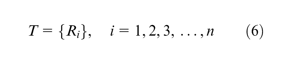
where T is known as the shape template and Ri is the shape constraints or shape rules of the ith segment. For line and arc segments, the shape rules are presented below.
The shape rules of a line segment
The shape of a line segment in the contour is described by a list with three conditions
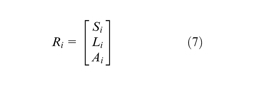
where the parameter S stands for type-of-segment, L for constraint of segment length, and A for rotational condition. Si has a constant value of “L” indicating it is a straight line. When there is no requirement for the length of the line segment, a special symbol, nil, is employed. When two segments are tangent to each other, the rotation reduces to 0. Otherwise, a rotational angle, from 0 to 2π, is specified.
With this convection, we can describe the shape in Figure 2 to be
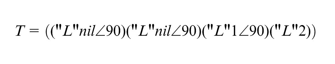
The above description of a shape is called a shape template (T), consisting of a set of constraints or rules. Note that the line lengths of the first and second segments are indicated by nil meaning that they are not constrained. This ensures that the length and width of the shape can be of any value. However, the length of their opposite sides is restrained. In the third set of the rule, it states that the line length is equal to the line length of segment 1. In the fourth set of rule, it says that the line length is equal to that of segment 2. An integer in the rule indicates that it is an equal relation: the current segment length is equal to the segment length so indicated by that integer.
If we are further interested in defining that the length of segments 1 and 3 is longer than that of 2 and 4, the above template will be modified to be
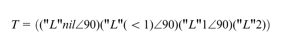
There are several ways to denote the length condition. They are given in Appendix 2. And the expressions for rotational condition of segments are given in Appendix 3.
The shape rules of an arc segment
The shape constraint of an arc segment is described in the format of
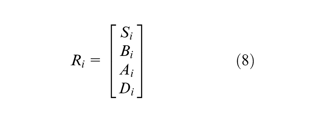
where Si is a constant, which stands for the type of segment and is assigned a string “A” for arc. B stands for constraints to bulge factor of the arc. It can be a “greater than,”“less than,” or “between a lower and upper bound” relation, or an integer to point to the bulge factor of another arc. The detailed specifications for the rules are given in Appendix 4. The rotational constraint, A, has the same meaning for a line segment. The radius constraint, D, in most cases, gives constraints for the relationship of the radius with respect to other arcs.
As an example, the shape in Figure 1(b) can be described by the following template
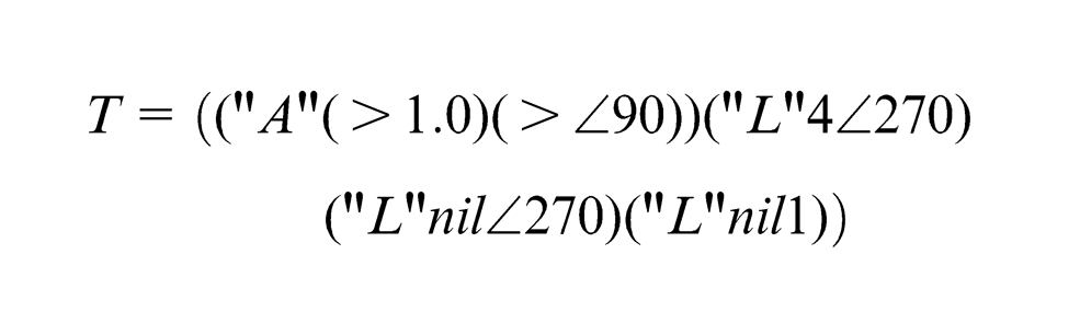
Note that the radius of the arc is free from being constrained. This means that it can be of any value.
Rules for developing shape templates
In developing a shape template, two points must be kept in mind. One is the robustness of the description: a set of rules must uniquely and correctly describe a shape. The other is its efficiency. Although a shape may be described correctly in several ways, the following two rules are to be followed for the consideration of computational efficiency:
Rule 1: when shape parameters of two segments are related, the relation (constraint) should always be given to the one that will first appear in the shape template. This is called the Priority Rule.
Rule 2: whenever possible, we should leave as many as possible parameters unconstrained. This is called the Free Constraint Rule.
Consider an example for using the Priority Rule: if the length of a line segment 1 is constrained to be the same as that of segment 2, (…(“L” 2)(“L”)…) is preferred to (…(“L”)(“L” 1)…). This is because at the time when shape conditions of segment 1 are not satisfied, it has concluded that the shape recognition has been failed. There is no need to test segment 2 anymore. If the constraint is given to segment 2, the same conclusion will be made after testing segment 2, one more step has to be taken.
For applying the Free Constraint Rule, we consider two examples here. Here is example 1: after we say “segment 1 has the same length as segment 2,” there is no need to say again that “segment 2 has the same length as segment 1.” This is because that “A = B” is the same as “B = A.” The same conditions should not be tested twice. Example 2 is like this: not all the rotational angles must be constrained because the total rotational angles for a closed shape will be a multiplication of 2π. One rotational angle can thus be unconstrained.
The library for shape definitions
As Meeran and Taib 11 write, most of the current available tools are based on a lexical form such as grammar or rule sets. In both cases, distinctive feature characteristics are used to identify the features (shapes). Invariably, these methods involve an exhaustive search that leads to an exponential increase in computing time as the number of features increases. To address this, we adopt a special database to store the shape knowledge. The format of the database is first proposed by Dong. 28 The generic format of the database is given in Appendix 5.
As, Bs, and Cs are indexes, and Vij is a set of parameters to be stored. This form of database is very suitable for storing engineering data, such as catalog data. With the present application, parameter A is designed to be the number of segments of contours and parameter B is the number of line segments (it is also possible to be the number of arcs). Parameter C is a serial number. The shape knowledge will go to the position of Vij . During shape recognition, the number of segments and number of line segments will be employed as indexes to retrieve the shape definitions and to allow only a small number of relevant rules to be used for checking.
The shape recognition device
The shape recognition device or the inference engine will read the shape data of a contour, retrieve relevant shape templates accordingly, and perform recognition reasoning by comparing the shape data with shape definitions that specify constraints for shapes. When a shape is successfully recognized, the shape code together with the dimensions of the contour will be returned.
A natural way for the implementation of the recognition device is to adopt the following algorithms:
Retrieve all the relevant shape knowledge or shape templates for a given contour and match the shape data with each of the shape template. This will cause the computational time proportional to M, where M is the number of templates, in the worst case.
For each given shape template, choose the first segment of the contour as the start segment and match the entire shape data with the shape template. This will cause the computational time to be proportional to N, where N is the number of segment.
If the above match fails, choose the next segment as the start segment and match for all the shape conditions of the N segment. This will continue until a shape is recognized or all the segments have become the start segment.
The total computational time is then proportional to MN 2 in the worst case as the brute-force solution to the problem. As discussed by Sedgewick 29 for typical pattern matching algorithms, researchers have proven that it is possible for the maximal running time to be reduced from N 2 to 2N. In the current problem, we too must seek the possibility of reducing the total computational time to 2MN.
The shape of a contour is recognized only when all the segment shape conditions are met with the predefined conditions. Therefore, this loop can never be simplified. The only way of optimizing the algorithm lies in the possibility of removing the loop to take turn for each segment to be the start segment. If and only if the start segment is described by some unique conditions, and it can be identified before matching the shape conditions of the rest N– 1 segments, can the computational time be reduced to 2N in the worst case. A study of the shapes listed in Face catalog for special punches shows that the answer is yes. For each parametric shape, it is always possible to identify one segment whose shape conditions (the relationship between its shape parameters with those of other segments) can be uniquely described against the shape parameters of the rest. If we take the four shapes given in Figure 1 as examples, the shape templates for the efficient algorithm are given in Appendix 6. The shape conditions in the first set of the rules describe the start segment.
Whenever the start segment is not found, the conclusion is made already that the shape parameters fail to match the shape conditions.
Now the improved algorithms become
Make a loop for matching the shape data to each shape template with the running time proportional to M.
For a given shape template and contour, identify the start segment. The running time for this is proportional to N in the worst case. If no start segment is found, there is no need to further verify the shape conditions for other segments. Otherwise, proceed to next step.
Match the next N– 1 shape conditions with the running time proportional to N– 1.
Thus, the total running time will be proportional to M (2N– 1) in the worst case. For large number of segments, we simply say that the running time is roughly proportional to 2MN in the worst case.
The computer algorithm is illustrated in Figures 3 and 4.
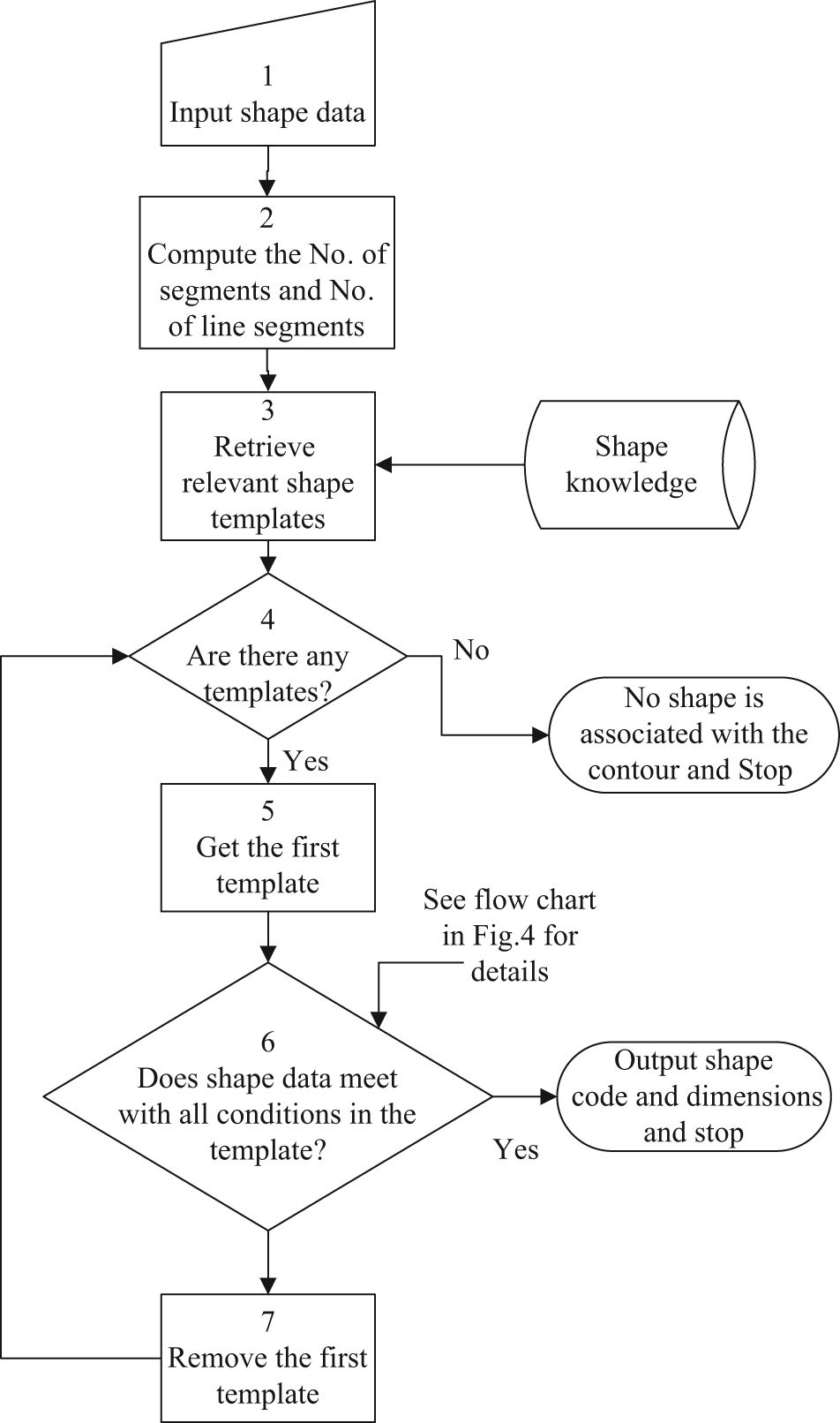
Flow chart of the overall process for recognizing a shape. A loop is made for the number of templates with the current contour.
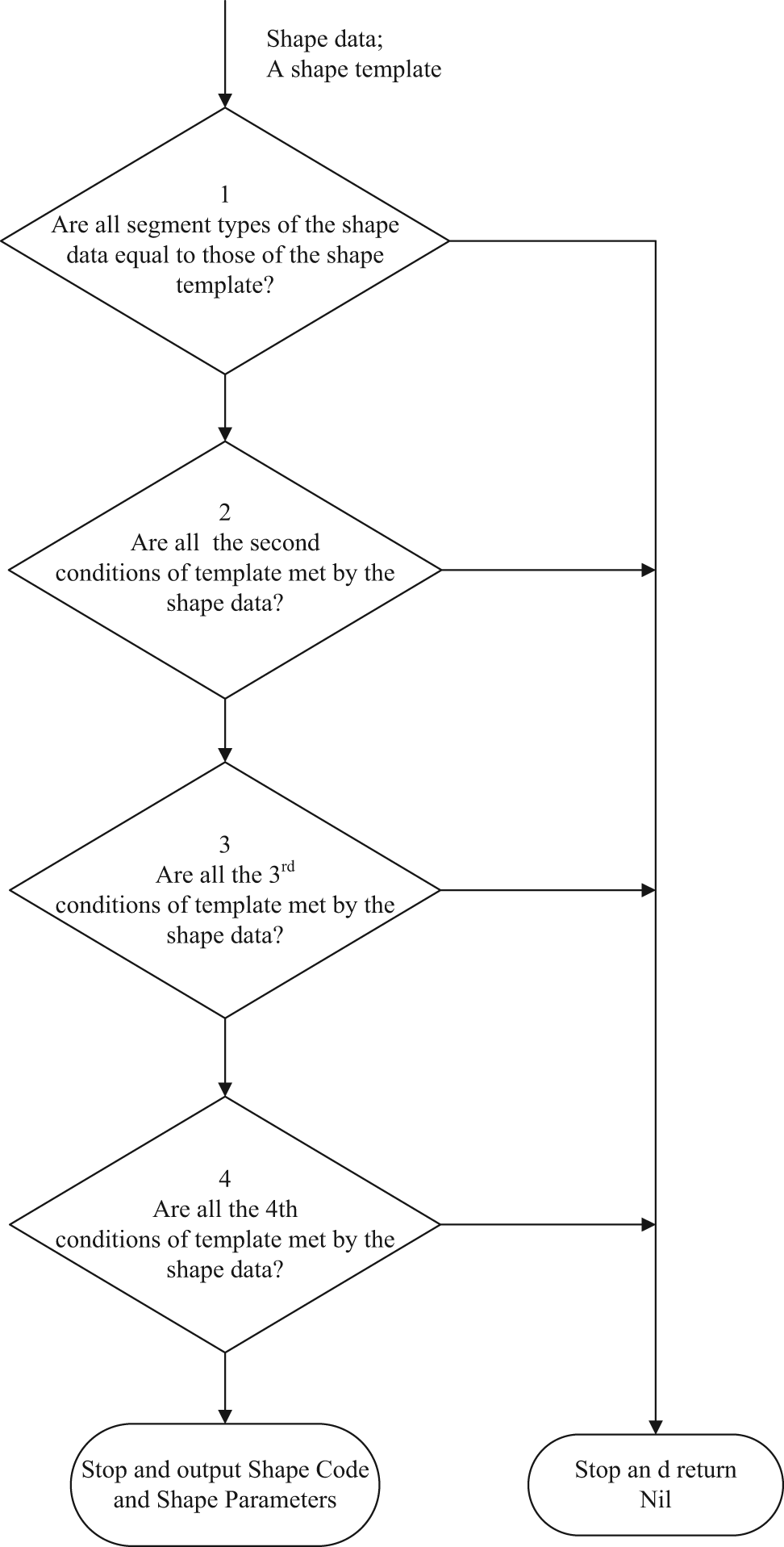
Computer algorithm to verify that shape parameters meet all the conditions of a shape template.
The post-processor
When the shape of a contour is recognized successfully, its shape code and geometric data (a list of vertexes and bulge factors) and shape parameters will be passed to this module for generating dimensional values and the orientation of the shape. Finally, post-processor will return these values for subsequent applications.
The results
The present shape recognition system has been implemented on the AutoCAD platform coded with Visual LISP. Knowledge base of about 120 parametric shape contours has been developed.
Different knowledge bases are developed for different applications. There is a need to assign a particular knowledge as the “current” knowledge. For example, one knowledge base is developed for standard punches, one for special punches, one for bending punches, and one for sheet metal part bending feature recognition. The shape recognition module is incorporated into various applications in order to automate these design processes. To apply the current shape recognition in AutoCAD, one only needs to concentrate on the knowledge of his interested application domains and subsequent design processes.
The present shape recognition module has been built into SMCAD and ComposerCAD for metal stamping dies. These have been widely used by industrial designers and also used as a teaching aid.
Discussion and conclusion
The methodology and advantages of this method
A generic method has been developed to allow automatic shape recognition for 2D contours that consist of lines and arcs in a CAD system. The knowledge about the shape is separate from the inference engine. The system can thus be extendable. The shape description rules can give simple relationships among segments and can also embed complex mathematical relationships. It is thus a more generic method for recognizing predefined shapes for the concerned class of contours. The method could be applied to develop a module for automatic dimensioning of recognizable contours, for recognizing standard punches and special punch shapes, and for recognizing bending profile in unfolding of bent part. These applications will be reported separately.
In this method, the description of the shape of a closed, non-intersecting contour is through a set of rules. They are simple and yet powerful. Essentially, three parameters are needed to control the shape component, which is essentially a vector: bulge factor, linear dimension, and rotational angle from one segment to another. Because the relationship between the segments in their length, included angles, radius, or rotational angles is linked each other, the method is powerful enough to model many practical complex shapes.
A comprehensive study of shape modeling and representation can be found in Cheok et al., 14 where the authors presented a systematic approach for shape representation using a contour-oriented approach. In a CAD environment, however, it is more convenient and straightforward to use the CAD parameters for shape representation. When model-matching technique18,19 is considered, this work has given a precise representation of the shape for piecewise smooth simple closed curves consisting of line and arc segments. That is, the bulge factor, linear dimension, and rotational angle between segments form the shape component for the representation of the shape of a contour.
The shape representation in the present system is achieved by using a set of rules or a shape template. Each template stands for a class of curves with that shape. Furthermore, this method of shape representation is one that allows the shape to be translated, scaled, and rotated. In the recognition process, the shape parameters are compared with the corresponding rules. Several loops are needed during the shape recognition, such as the loop for each segment to be the starting one, and the loop for each relevant template.
We adopt AutoCAD entity data polyline as the source of curves. By default, there are two possible directions for such a curve, clockwise and anti-clockwise. Thus, two definitions have to be used for one shape representation if two directions are considered. To save this trouble, we use an algorithm to ensure that only shape data of anti-clockwise direction are extracted.
Limitations of the shape recognition approach
While the current method is powerful in recognizing any 2D shapes, the shape must be predefined. For applications where the actual shapes can never be predicted, this method will fail to apply. One example is to automatically create intelligent dimensions for any possible irregular shapes. In such a case, we have to focus on recognizing the local features of the curve, such as fillet and chamfers, rather than the overall shape, and generate ordinate dimensions instead of linear and angular dimensions. Shapes must be predefined is a universal limitation of shape recognition approach. The number of shape templates may grow dramatically as more and more shapes are considered. This will eventually slow down the system’s performance. One way of overcoming this problem is to divide a problem to be solved into smaller problems. For each particular problem to be solved, a shape library is developed. At any time, only one shape library is loaded as the current working shape templates. When current high-performance PC is used, then, efficiency does not seem to be a problem anymore.
The following conclusions can be made through this study:
A shape can be defined with a number of rules that consist of a list of symbols, strings, sublists, and numbers. These rules set constraints for and relationships between essential shape parameters such as the bulge factor, segment length, and rotational angle for different segments of a contour.
The shape knowledge and the inference engine can be separated. This makes possible for the system to be extensible for different applications and one only concentrate on the definition of shapes once the inference engine is developed.
The efficiency of reasoning for shapes can be significantly improved when a special format of knowledge base is adopted to allow minimum number of shape templates to be retrieved and by identifying unique shape conditions of the start segment.
Footnotes
Appendix 1
Appendix 5
Acknowledgements
The authors want to thank Prof. Wang Jiaye of Shandong University, China, for his advice in optimizing the computer algorithms in the implementation of the computer system. They are also grateful to Mr Shi Chengfu for his significant contributions in the project as a programmer.
Declaration of conflicting interests
The authors declare that there is no conflict of interest.
Funding
This project was supported by NSTIP strategic technologies programs, under Grant No. 12-INF2816-02, in the Kingdom of Saudi Arabia.