
Abstract
This paper presents dynamic characterization and control of an upper-limb rehabilitation machine aimed at improving robot performance in the interaction with the patient. An integrated approach between mechanics and control is the key issue of the paper for the development of a robotic machine with desirable dynamic properties. Robot inertial and acceleration properties are studied in the workspace via a graphical representation based on ellipses. Robot friction is experimentally retrieved by means of a parametric identification procedure. A current-based impedance control is developed in order to compensate for friction and enhance control performance in the interaction with the patient by means of force feedback, without increasing system inertia. To this end, servo-amplifier motor currents are monitored to provide force feedback in the interaction, thus avoiding the need for force sensors mounted at the robot end-effector. Current-based impedance control is implemented on the robot; experimental results in free space as well as in constrained space are provided.
1. Introduction
The design process of a robotic machine for robot-aided neurorehabilitation develops in a highly collaborative research scenario where roboticists, neuroscientists and medical doctors define system specifications. The main reason for this is that the human subject (i.e. the patient exposed to the rehabilitation therapy) plays a key role in the design in view of the tight and continuous physical human-robot coupling [1]–[3]. The robot helps the subjects to carry out part of the task that they are not able to perform autonomously, with a level of assistance that can be adapted to their residual abilities [4]. Requirements such as accuracy, repeatability, pre-programmed movements and task specificity (typical of industrial or service robots [5], [6]) yield to priorities imposed by the close physical contact with the user, such as safety, reliability, robustness, adaptability and back-driveability (i.e. low mechanical impedance). All these features depend on the robot mechanical and control design [7]–[9] and can be addressed by means of a mechatronic approach, where the optimal combination of mechanics and control is searched for in order to address requirements coming from the specific application context. The same requirements can also be applied to robotic devices used to study human arm stiffness [10], [11].
Several examples of robotic machines for rehabilitation can be found in the literature [20]–[30]. They can be classified into two main groups, according to the followed design approach.
The first one consists of adapting or reconfiguring industrial robots in order to be used in rehabilitation [21]–[23]. This approach has the consequent critical drawback that low impedance comparable to that of the human arm cannot practically be obtained, since these robots are intrinsically position-controlled. Despite the use of active force feedback to enhance robot responsiveness, the backdriveability required to move smoothly and rapidly in compliance with patients' actions [31] is not achieved. High inertia, anisotropy of dynamic properties and low acceleration capabilities are often mainly responsible for that [32], [33].
The second approach consists of designing robots specifically conceived for tight human-machine interaction and includes two main classes of systems [22]:
Class I machines. System backdriveability is achieved through mechanical solutions that aim to minimize the perceived inertia, as for the haptic interfaces [36], [37], [9]. They have low mechanical inertia and friction, fine tuning of the visco-elastic properties, and high cost [34], [35], [38].
Class II machines. They have a simple mechanical structure, no mechanical backdriveability, non-negligible inertia, possible presence of friction and a low cost. Class II machines rely on combined solutions of mechanics and control to overcome such limitations. They are very interesting for their applicability to remote rehabilitation (i.e. tele-rehabilitation)[39], justified by the low cost and the simplicity of functioning mode.
For both Class I and Class II systems, control design typically resorts to traditional approaches, e.g. stiff PID voltage control (i.e. a proportional-integral-derivative action), compliance control and impedance control [40], [41]. By analogy with [5], [53], in this paper the term compliance control is referred to interaction control based on a proportional-derivative action plus gravity compensation; on the other hand, impedance control refers to inverse dynamics interaction control.
Rehabilitation robotic machines can be regarded as a paradigmatic example of mechatronic systems. Nevertheless, quite surprisingly, highly nonlinear phenomena able to strongly degrade robot performance, such as friction, are often neglected in their design.
Friction models proposed in the literature [12], [13] point to the complexity of the physical phenomenon and the variability of its features with temperature and different lubrication conditions. The difficulty in managing this leads to a tendency to neglect it. The main studies on friction compensation are in the fields of industrial and service robotics. Friction can be experimentally identified and compensated by the control [14]–[16], and its variability in the robot workspace can be tackled by the use of adaptive control laws [17]–[19].
In this work, an integrated approach between mechanics and control is proposed for the development of the CBM-Motus, a planar robot for upper-limb rehabilitation [48]. The system aims to go beyond the current state of the art in terms of low and isotropic inertia, still belonging to Class II robots. In other words, the CBM-Motus has a simple mechanical structure and is characterized by inertia ellipses with small radius and unitary eccentricity, which are independent of the robot configuration in the workspace [50], [51]. The CBM-Motus has been conceived for tele-rehabilitation applications, thus aiming to be highly dependable, low cost and portable. The resulting machine is light, compact and robust, designed to be transported and mounted at the patient's site with no or negligible need for specialized skills. However, a complete dynamic characterization of the robot has shown non-negligible friction and reduced capability of visco-elastic regulation. An interaction control able to cope with these two issues is proposed. The key points of the control system (named “current-based impedance control”) are:
Friction compensation and tuning of robot compliance by means of an interaction control law based on inverse dynamics compensation;
Closed-loop control based on measured electric currents (in lieu of traditionally used force sensors) in addition to position feedback. Current monitoring plays a fundamental role in fine tuning of the robot impedance during interaction by providing an indirect force feedback in the control loop.
Previous examples of robot control based on current monitoring or force sensorless approaches can be found in the literature. They resort to artificial neural networks [42] and neuro-fuzzy approaches [43], [44] for current characterization in a structured environment, or else to observers for force/torque estimation [45], [46], and are typically applied to the industrial context, such as for indirect cutting force measurement [42], [43]. Only recently, an extension to force control of a mechanical finger for prosthetics has been published [47].
Here, the use of servo-amplifier motor currents in the control loop is proposed because of the twofold benefit of (i) avoiding an increase of mechanical inertia and wiring problems caused by a force sensor mounted at the robot end-effector; (ii) improving control performance with respect to traditional control based on sole position feedback. A servo-amplifier motor current characterization based on a linear regression analysis is proposed in this paper and an application to impedance control is carried out.
The CBM-Motus mechanical design, kinematics and dynamics are described in Sect. 2. The study of robot dynamic properties through inertial and acceleration ellipses is proposed in Sect. 3. The method, inspired by previous works on the dynamic optimization of robot design [50], [51], allows studying the robot inertia and acceleration characteristics as perceived at the end-effector. Section 4 concentrates on the experimental identification of the static and dynamic friction of the robot; a parameter identification procedure based on a least-squares technique is used to estimate dynamic friction. Section 5 provides the theoretical formulation of current-based impedance control, while Sect. 6 reports data coming from the experimental validation in free and constrained space.
2. CBM-Motus Robotic Machine
2.1. Mechanical Design
The CBM-Motus is a planar robot for the neurorehabilitation of the upper-limb with a workspace of 0.5 × 0.5 m. It has a Cartesian kinematic structure consisting of two modules, each corresponding to an actuated axis [48]. As shown in Fig. 1, each module includes six pulleys with the same radius (R = 0.025 m) and two timing belts (9.4 mm wide, reinforced with a glass fibre cord). Two couples of pulleys (on the left in Fig. 1) are mounted on the same shaft, while one pulley per module is directly driven by the motor with no reduction gearing interposed. Two belts for each module are mounted in such a way that the points along the segments AB and CD move vertically with the same speed. A ground stainless steel bar is fixed to a couple of such points, e.g. P and P' in Fig. 1. The second module is connected to the robot frame with a rotation of 90° with respect to the first module. The end-effector of the robot, i.e. the handle grasped by the patient, is connected to both bars, at their minimum distance points, through a couple of orthogonal prismatic joints, rigidly linked together to make a single compound joint, in the following referred to as double prismatic joint. Friction at each prismatic joint (still remaining non-negligible because of the sliding motion) is reduced by means of linear ball bushings.
Both ends of each bar are connected to the driving belts. The outer prismatic joints (P1,…, P4) correspond to the segments of the belts to which the two bars (1 and 2) are connected (see Fig. 2(a)). The two bars slide through the compound prismatic joint (A + B), to which the end-effector (E) is connected.
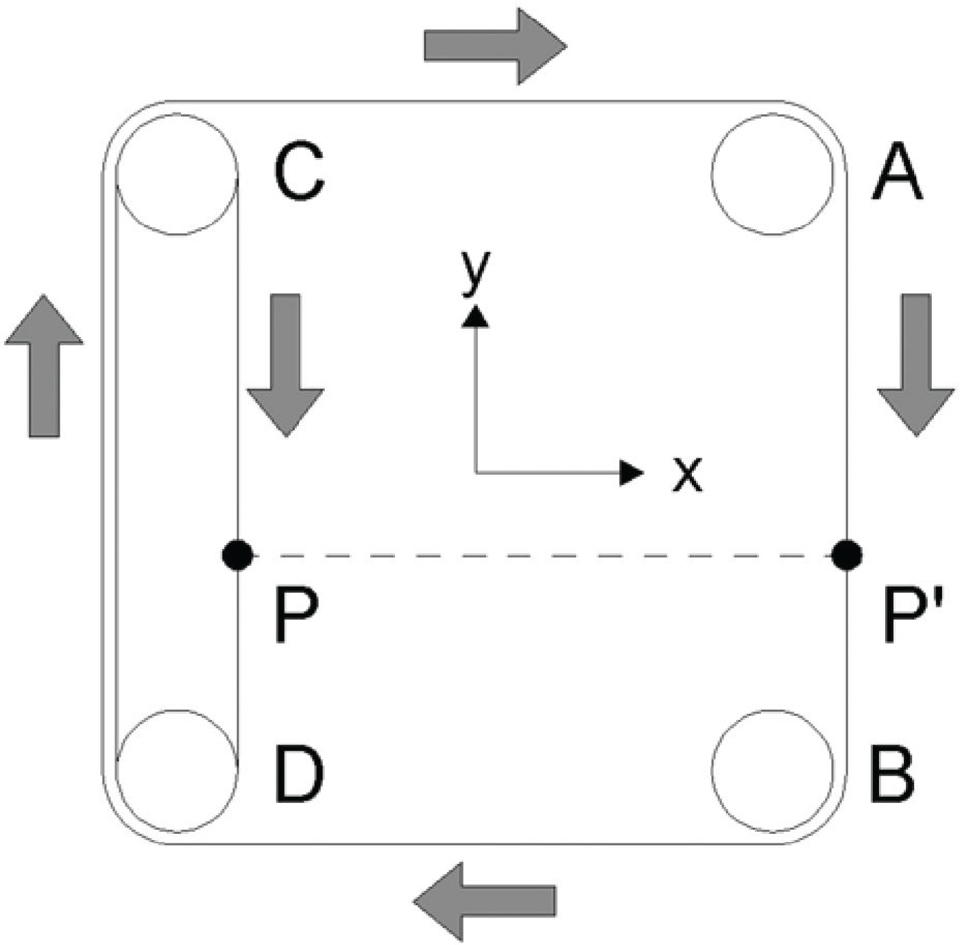
Schematic of a single kinematic module comprising 6 pulleys and 2 belts. P and P' move vertically with the same speed.

(a) CBM-Motus kinematic scheme; (b) Overview of the complete robot.
This patented kinematic architecture [49] has the main feature of ensuring a good rigidity of the robot with relatively small moving masses, because the double prismatic joint assures that only tensile forces are transmitted to the belts. In order to balance vertical loads and axial forces caused by friction in the prismatic joints, the ends of the bars are supported by a ball-bearing slider.
The two modules are directly driven by DC servomotors (Aerotech BM 250) with rated torque of 2 Nm and peak torque of 5 Nm. Being R = 0.025 m the radius of the pulleys, the rated force which the robot is able to exert is 80 N for each axis, with a peak force of 200 N. For safety purposes, the maximum exercisable force was limited via software to 50 N. The overall dimensions of the robot frame are 0.83 × 0.82 × 0.11 m. The total mass (frame and motors included) is less than 30 kg. The overview of the system is shown in Fig. 2(b).
2.2. Robot Kinematics and Dynamics
The CBM-Motus robot can be regarded as a Cartesian manipulator with two linear joints d1 and d2. The kinematic model of the robot (Fig. 2(a)) is very simple. The end-effector Cartesian position and the Jacobian matrix can be expressed as:

The robot dynamic model is given by:

being ξ = τ – Fvq̇ – fs(q, q̇). In particular, τ is the joint torque vector, Fvq̇ is the viscous friction, fs(q, q̇) is the static friction, B is the inertia matrix (independent of the robot configuration), and c(q, q̇) = [0 0] T is the vector of centrifugal and Coriolis torques. Matrix B can be expressed as:

where ml1 and ml2 indicate the translating masses, including bars, belts and handle, and I m 1 = Im + 6Ip with Im2 = Im1 are the moments of inertia due to the two motors and the six pulleys.
3. Inertia and Acceleration Ellipses
The study of the CBM-Motus dynamic properties was carried out through an ellipse-based representation of the robot inertial and acceleration capabilities in the 2D workspace. It resorts to the approach in [50], [51].
This characterization allowed studying the level of isotropy and the magnitude of robot inertia and acceleration in the workspace. For upper-limb rehabilitation the following requirements are necessary:
Motion isotropy: robot dynamic properties (as perceived by the patients) need to be the same in each direction of the workspace; this enables highly repeatable upper-limb training all over the workspace, without additional difficulty caused by the robot anisotropic dynamic features.
Low inertia perceived by the patient: this is one of the fundamental items (together with efficiency) to achieve robot backdriveability. Low inertia is a desirable feature during the two phases of patient therapy and evaluation. Mainly in the evaluation phase, low inertia is strictly related to robot mechanical properties (even if mechatronic solutions can also be implemented). On the other hand, there are not strict requirements on the acceleration magnitude; because of the slow patient motion, high acceleration is not required.
3.1. Inertia Ellipses
Given CBM-Motus inertia matrix B(q) in the joint space, matrix Λ(q), defined as:
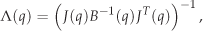
is the generalized inertia tensor [50] and, once a unit vector u along a direction has been assigned, the equation

describes a generalized inertia ellipse (GIE) having the following properties:
- the principal axes are aligned with Λ eigenvectors λ(Λ);
- the length of each principal axis is
The inertial features of the robot are related to ellipse features through
‖Λ‖, which describes the magnitude of inertial properties (the robot design tends to minimize them);
k (Λv) (where k(·) is the matrix condition number), which describes the extent of isotropicity of the inertial properties (when k (Λv) = 1 robot inertia is isotropic).
The CBM-Motus inertia graphical representation is provided for a typical rehabilitation task covering a meaningful portion of the robot workspace; it is the clock task shown in Fig. 3, as typically used for motor rehabilitation therapy [52].

Graphical interface for the rehabilitation clock exercise.
Figure 4(a) shows the inertia ellipses for the CBM-Motus in the nine Cartesian positions (P1,.., P9) that the robot reaches while performing the rehabilitation clock task. Inertia is isotropic (k (ΛvMotus) = 1) and the inertia ellipses become circles. Their magnitude is 2.026 Kg, meaning that the inertia is independent of the robot configuration. Thus, the mass perceived at the end-effector has the same value everywhere in the workspace and is given by 2.026 Kg; it is of the same order of magnitude as that of the MIT-Manus robot (i.e. the golden standard Class I robot in upper-limb rehabilitation) [26], [48].
3.2. Acceleration Ellipses
Given the torque boundary condition

where τbound is the vector of maximum actuator torques, the torque ellipse for linear acceleration is described by:

being

and

with

and

The ellipse is described by the core matrix (EvETv)†, where E†v = (ETvEV)−1 ETv is the right pseudo-inverse matrix of Ev. For details on the theoretical formulation see [51], [48]. The acceleration capabilities of the robot can be evaluated by means of
‖Ev‖, which measures the magnitude of acceleration capability (minimizing it means maximizing the acceleration);
k(Ev), which measures isotropicity of acceleration capabilities, as for the inertia.
Mapping a circle into the square defined by the torque bounds is the best possible situation; it represents an isotropic acceleration capability while most of the available actuator torque capability is used.
Similarly to the inertia analysis, Fig. 4(b) shows the ellipses related to the acceleration in the nine positions of the clock task. CBM-Motus acceleration features are isotropic (k (EvMotus) = 1) with a constant value of ‖EvMotus‖ = 0.41 s2. The maximum acceleration is 3.5 m/s2. This value satisfies the condition of tangency with the square of torque bounds.
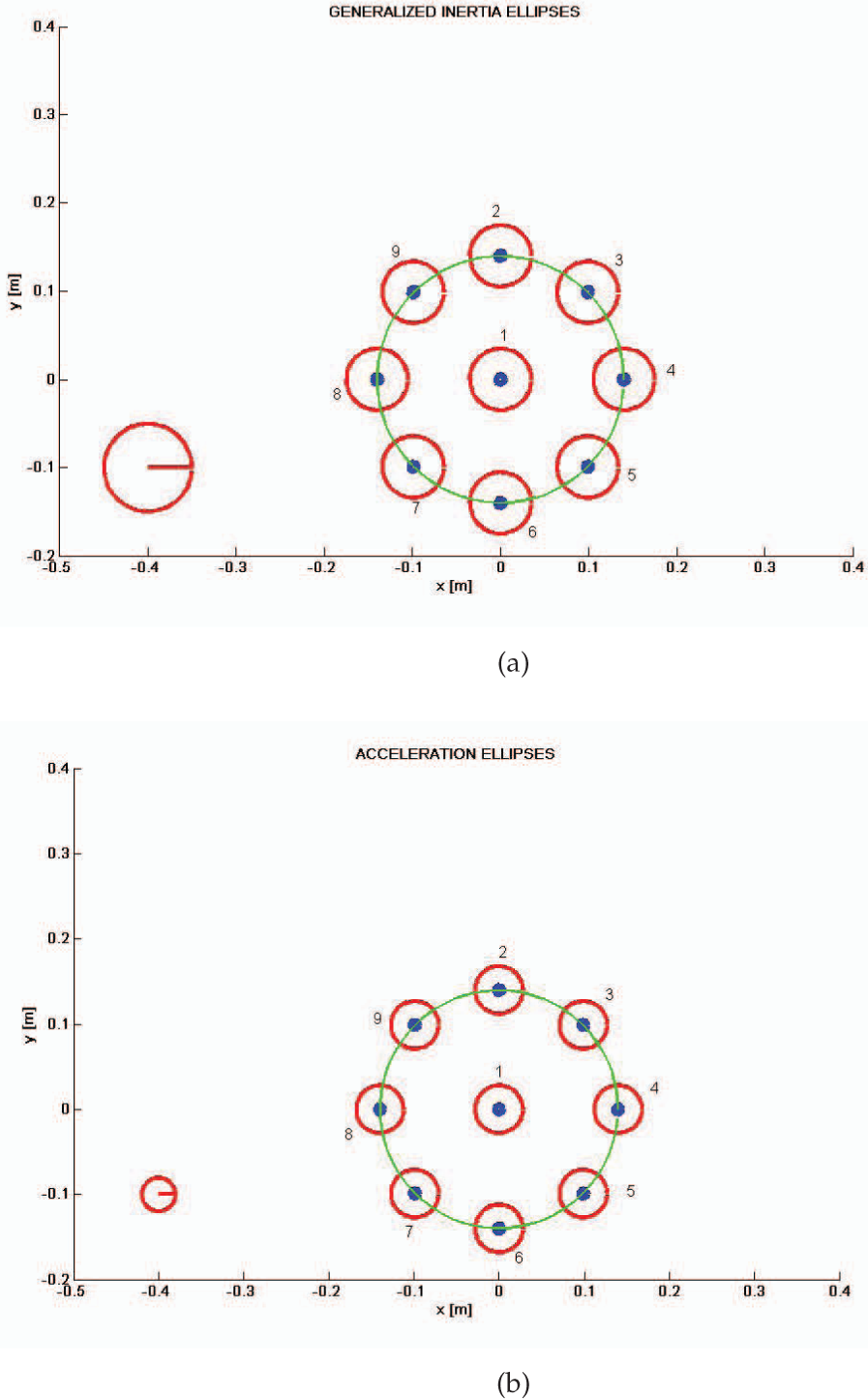
(a) Inertia ellipses for the CBM-Motus robot during the rehabilitation clock exercise. (b) Acceleration ellipses for the CBM-Motus robot during the rehabilitation clock exercise.
4. Friction Identification
The characterization of the robot dynamic properties was completed through the identification of friction; this aimed at verifying whether the hypothesis of negligibility was applicable. To this end, static and dynamic friction forces were experimentally retrieved.
For the static friction, a set of experimental trials in the robot workspace were carried out in order to define the minimum value of the electric currents needed to move the end-effector. For each trial, the value of static friction force for each axis was extracted by means of the following relation:
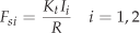
where Kt = 0.19 Nm · A−1 is the motor torque-current constant, taken from the data sheet of the motor, R is the radius of the pulley and I is the current of the actuated motor. Using Student's t-distribution, the confidence interval of friction measurement can be expressed as:

where F̄si is the truemean of the static friction force, σ is the standard deviation and tα,N–1 is t-value for N = 10 trials and statistical significance α = 0.05. For the two linear joints, the following values were obtained:

On the other hand, for the dynamic friction (modelled as viscous friction), a parametric identification procedure based on a least-squares technique was applied [53]. In particular, friction coefficients Fvi of diagonal matrix Fv in Eq. (2) were extracted, given the other robot dynamic parameters. To this end, the linearity property of the robot dynamic model with respect to dynamic parameters was used, as described in the following:
where π is the (p × 1) vector of unknown parameters, τ̄ is the (n × 1) vector of measured joint torques and Y(q,q̇, q̈) is the (n × p) regression matrix, considering that n indicates robot degrees of freedom (i.e. dof) and p the number of unknown dynamic parameters.
For the CBM-Motus, vector τ̄, matrix Y and vector π can be written as follows:

Assuming that Mrepresents the number of trials and N the number of time instants for each trial, Eq. (12) becomes:

being Y˜ a (nNM × p) matrix, and the convergence of the method is guaranteed for nN ≫ p [53]. In order to identify viscous friction coefficients, 20 trials were carried out in the workspace, each lasting 1 s with sample time of 10 ms.
The unknown vector π of viscous friction coefficients was obtained by inverting Eq. (14) by means of the left pseudo-inverse matrix of Y˜, as follows:

thus yielding to the following values (expressed in Ns/m):

As expected, dry friction was non-negligible being the value of static friction around 4 – 5% of the maximum force value that the robot can generate (50 N); it requires 0.25 A along x and 0.30 A along y to be won, which is about 60% of average current values in normal operating conditions during a point to point motion in free space lasting 2 s (mean current is 0.42 A along x and 0.47 A along y). On the other hand, viscous friction reaches 2.1% and 2.7% of the maximum force value along x and y axis, respectively, in normal operating conditions of 0.3 m/s in unconstrained motion.
The procedure was automatized in order to account for the dependence of the friction parameters on environmental conditions. Thus, they are evaluated every time the machine is turned on. However, friction parameters might depend on the force applied to the end-effector and, more in general, on the robot configuration. In order to address this issue by avoiding calculating friction values for each configuration, the identification procedure is carried out in the worst region of the robot workspace, i.e. where friction is the highest, and the obtained values are used in the control scheme for friction compensation. The effect of such a choice on robot control is shown in the experimental section.
5. Theoretical Formulation of Current-based Impedance Control
Notwithstanding the optimal dynamic features of the robot in terms of inertia and acceleration at the end-effector, the presence of non-negligible friction experimentally estimated makes compliance control unsuitable for regulating visco-elastic properties of the robot in the interaction with the patient. Hence, for the CBM-Motus the approach based on impedance control was chosen. However, in order to keep inertia low and solve wiring issues, the use of a force sensor mounted at the end-effector was avoided. Thus, an impedance control based on servo-amplifier current feedback (namely ‘current-based impedance control’) was developed. The measure of servo-amplifier electric current was used as an indirect measure of interaction force and fed back in addition to position readings from the encoders. This approach is particularly interesting as (i) it behaves as an impedance control with force feedback; (ii) it does not require force sensors and solves problems related to the increase of the apparent inertia perceived by a human user (due to force sensor mass), wiring issues and costs of the sensors; (iii) it is general and can be applied to rehabilitation robotic machines with electric actuation, where inertia and acceleration are typically low.
Theoretical formulation of current-based impedance control resorts to the general form of robot dynamics in the interaction with the patient, expressed as:

where JT(q)h is the torque contribution due to the interaction force h exerted by the patient on the robot.
The control law can be written as:

where h(I) is the interaction force extracted from the sensed current I. Thanks to the term JT(q)h(I), replacing (18) in (17) yields to

Adaptation with respect to interaction force is obtained by means of y, which is defined as:

where J is the Jacobian matrix, x˜ = xd – x and
In the interaction with the patient, the behaviour of the robot can be described as follows:

The robot behaves as a generalized mechanical impedance regulated through a mass matrix Md, a stiffness matrix KP and a damping matrix KD. Current-based impedance control can linearize robot dynamics, also in the absence of a force sensor at the end-effector; consequently, patient-robot interaction can be regarded as the parallel of two mechanical impedances (one for the human arm, one for the robot) and at the equilibrium the elastic term of the robot directly balances the force exerted by the patient.
6. Experimental Validation of Current-based Impedance Control
6.1. Identification of CBM-Motus Force/Current Relation
The idea behind current-based impedance control is to measure interaction force by means of current monitoring in place of direct force monitoring. This entails the need for identifying a relation between electric current and interaction force in the whole robot workspace, by distinguishing current values during free motion (i.e. without interaction) from current values in constrained motion (i.e. during interaction).
The experimental trials for force/current characterization rely on the following assumption: current variation from its typical value in free motion is due to a force applied to the end-effector and is an indirect measure of it. Hence, force/current characterization consists of two basic steps: (i) synchronized acquisition of forces and currents in free motion and constrained motion; (ii) correlation analysis of previously acquired current and force data.
The experimental setup consisted of two different data acquisition systems. They were opportunely synchronized and dedicated to measure forces and currents, respectively.
The force acquisition system was made up of a six-axis JR3 force/torque sensor with a full scale of 100.00 N, a resolution of 0.01 N and a mass of 0.30 kg. It was mounted on the double prismatic joint of the CBM-Motus handle and was connected to a National Instruments Data Acquisition card (NI USB 6009). NI LabVIEW SignalExpress® and MATLAB® software packages were used for data acquisition and processing. A low-pass first order Butterworth filter with cutoff frequency of 30 Hz was used for filtering force data, acquired by an NI analogue to digital converter with a sampling frequency of 1 kHz.
On the other hand, current values were acquired by means of the CBM-Motus Digital Servo Amplifiers (Ndrive CP20), with a servo loop update rate of 8 kHz. Robot control was programmed in C language with a time-step of 10 ms and the communication was established through a Ndrive CP20 board via Firewire connection. An overview of the experimental setup is shown in Fig. 5.
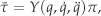
The robot was programmed to perform 500 point-to-point movements along different directions of the workspace, as shown in Fig. 6(a), in conditions of free motion and constrained motion. In the case of constrained motion, the robot was required to perform a point-to-point motion with a known mass applied to the end-effector, by means of a pulley-string system shown in Fig. 6(b). Four different experimental conditions were analysed, corresponding to four different values of applied mass (0.2 kg, 0.4 kg, 1.0 kg, and 2.0 kg), in addition to the case of null mass.

Experimental setup for force and current recordings.
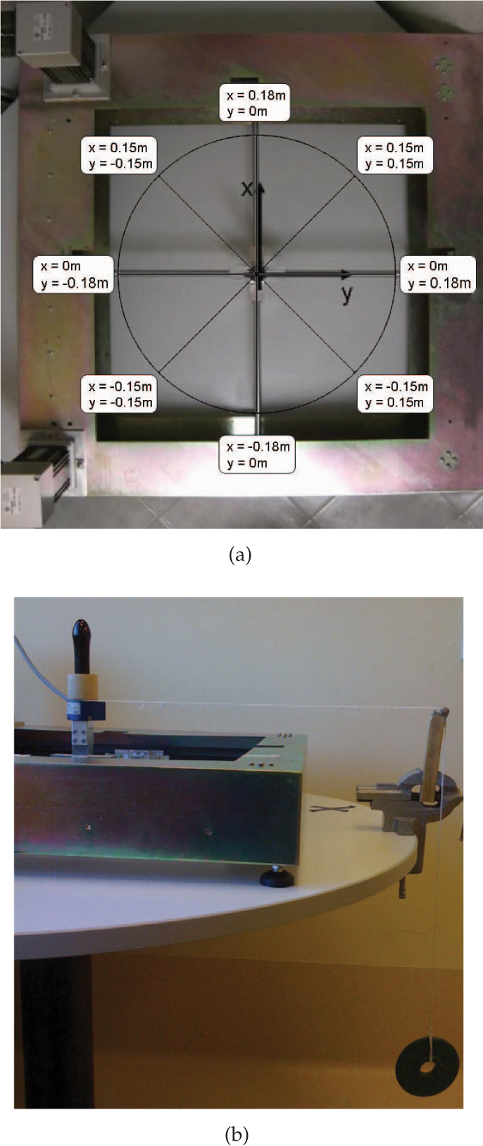
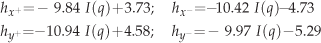
Because of the non-negligible and anisotropic friction distribution in the robot workspace, four separate linear regression analyses were required for directions towards positive and negative x and y axes (i.e. x+, y+, x−, y−) (Fig. 7). Each experimental point represents the mean value of a set of 10 trials for each mass value; x and y axes are referred to joint 1 and 2, respectively.
(a) Motion directions of the CBM-Motus workspace used for the linear regression analysis; (b) Pulley-string system for force/current characterization.
The analytical expressions of the four linear regression functions for each robot configuration are as follows:
where forces are expressed in [N] and currents in [A]. It is worth noticing that they are valid when motion occurs along both axes and the other dynamic terms are compensated. Solving Eqs. (22) with respect to current in the absence of interaction force (hx± = hy± = 0) provides current mean values in the free space for each direction.
On the other hand, when only one axis is commanded to move, the force/current relation for the unmoved axis changes as follows:

Finally, the mean error between the force measured by the force/torque sensor and the force computed by the electric currents is shown in Fig. 8. It was averaged over positive and negative directions of x and y axes and varied in the range [0.30, 1.37] N.
Regression functions for motion directions towards positive and negative x and y axes. R is the Pearson correlation coefficient for each linear function.

Mean error between the force measured by the force/torque sensor and the force computed by the electric current.
6.2. Experimental Results
The experimental session aimed at proving the efficacy of friction compensation in improving robot performance and the efficacy of servo-amplifier current monitoring in regulating interaction forces. To this end, experimental trials in the free space were carried out with and without friction compensation. The robot was commanded to track a minimum-jerk trajectory (i.e. a quintic polynomial function) from P1 to the eight points P2–P9 of the clock exercise in Fig. 4; an inverse dynamics control given by Eqs. (18)–(20) in the absence of interaction was used in the two cases of friction compensation and non-compensation.
Figures 9(a) and 9(b) show the desired and actual end-effector trajectories, position error in norm, recorded electric currents and current-based force when the robot is moving in the free space in the cases of friction compensation and non-compensation, respectively. As expected, the values of static and dynamic friction identified with the procedure in Sect. 3 can notably reduce the position error from a mean value of 0.0145 m to a mean value of 0.0017 m, which is comparable with other robotic machines for upper-limb rehabilitation such as the MIT-Manus [26]. Table 1 reports mean position errors for the eight point-to-point motion tasks in the clock exercise. The error obtained in the case of non-compensated friction is always one order of magnitude higher than the case with compensated friction. Moreover, as expected, the error along y-axis is slightly higher, because of the higher friction.
Furthermore, Table 2 reports: the rated force and peak force enabled by the actuation system, the achievable force (as imposed via software for safety reasons), and the minimum achievable force with and without friction compensation. Note that the value of minimum achievable force, in the case of friction compensation, leads robot impedance close to zero. The upper limit of robot impedance is imposed by the maximum achievable force (i.e. 50 N), which is limited via software.
Additionally, force/current relations in Eqs. (22) were used in Eqs. (18)–(20) to implement and test current-based impedance control. The experimental session aimed to validate the control approach in the interaction with an external environment (i.e. constrained motion) and to verify if the applied forces were compatible with the application addressed (i.e. robot-aided rehabilitation). Friction was compensated in addition to robot inertia.
Mean position error with and without friction compensation during the eight point-to-point motion tasks of the clock exercise.

Robot force performance.

For constrained tasks, the same trajectory as for the free motion was planned and the robot was required to move with a weight constantly applied at the end-effector, as shown in Fig. 6. Different mass values were tested with the control law by varying control gains and measuring the corresponding end-effector position and motor currents. Table 3 reports the maximum values of position error and current-based forces obtained with two different values of control gains for the constrained motion with two different weights applied at the end-effector and for motion in the free space.
Figures 10(a) – 10(b) report the desired and actual end-effector trajectories, position error in norm and recorded electric currents for current-based impedance control, when a weight of 1 kg is applied and two different sets of control gains are chosen (KP = diag{40, 40}, KD = diag{4, 4} and KP = diag{100, 100}, KD = diag{10, 10}). Additionally, force values extracted from the electric currents are shown in Figs. 10(a) – 10(b) (bottom right). As expected, the robot pulls the weight with a level of force that depends on the control gains; however, it is not able to reach the final target because of the applied weight. Control gains were empirically chosen in order to set two different levels of robot compliance within system stability limits. Force values correspond to the average peak force values measured on patients in two typical working conditions in robot-aided rehabilitation, i.e. unperturbed point-to-point motion and resistive motion [54]. It can be noticed that the computed force value is constant as long as the robot end-effector holds the position imposed by the applied weight. A threshold check is made on the electric current, so that when during interaction it goes below 0.57 A for x axis and 0.62 A for y axis (as an effect of the torque control command), interaction force is maintained constant with the position. When the current is beyond the threshold, force values vary according to relations (22). The threshold values correspond to the maximum current values for each axis in free space motion.
Performance of current-based impedance control with different weights and control gains.

Note that, with the same set of gain values KP = diag{100, 100} and KD = diag{10, 10}, current-based impedance control allows ensuring a high level of adaptability to the external constraint (h = 21.41 N in Fig. 10(b)) and, at the same time, a good level of accuracy in free motion (0.004 m is the maximum value of Cartesian position error in Fig. 9(a)). Thus, the proposed control allows compensating for the drawback of friction and preserving favourable robot dynamic features in terms of isotropy and low inertia, also making the system selective with respect to motion direction. Obviously, the better the friction estimation, the better the robot performance.
It is worth noticing that extracting force values from servo-amplifier current measures could cause a slight reduction of system reactivity; the reason for this is that interaction force is perceived when a significant change in current level is induced. This means that perception of the interaction force can be delayed of one sample time in the worst case, corresponding to 10 ms in the performed experiments. However, as experimentally verified in our tests, this is not critical in applications of robot-aided rehabilitation where motion velocity is very low (under 0.2 – 0.4 m/s).
Finally, software safety measures were taken in order to minimize the risk of injury to subjects during the experimental trials, potentially caused by an electrically actuated machine capable of autonomous motion. Specifically, the software continuously monitors torques, velocities and displacements, and disables the system in the case where pre-established limits are exceeded.
7. Conclusions
This paper presented an integrated approach between mechanics and control for the development of an upper-limb rehabilitation machine with desirable dynamic features in terms of human-robot interaction. Dynamic characterization and control of the rehabilitation robot were proposed. Robot characterization through ellipses graphical representation was proposed for inertia and acceleration, while parametric identification was used for estimating friction. An impedance control based on inverse dynamics and electric current feedback was proposed in order to compensate for friction and improve system performance in the interaction with the patient without the increase of moving masses and wiring that would result from the addition of a force sensor.
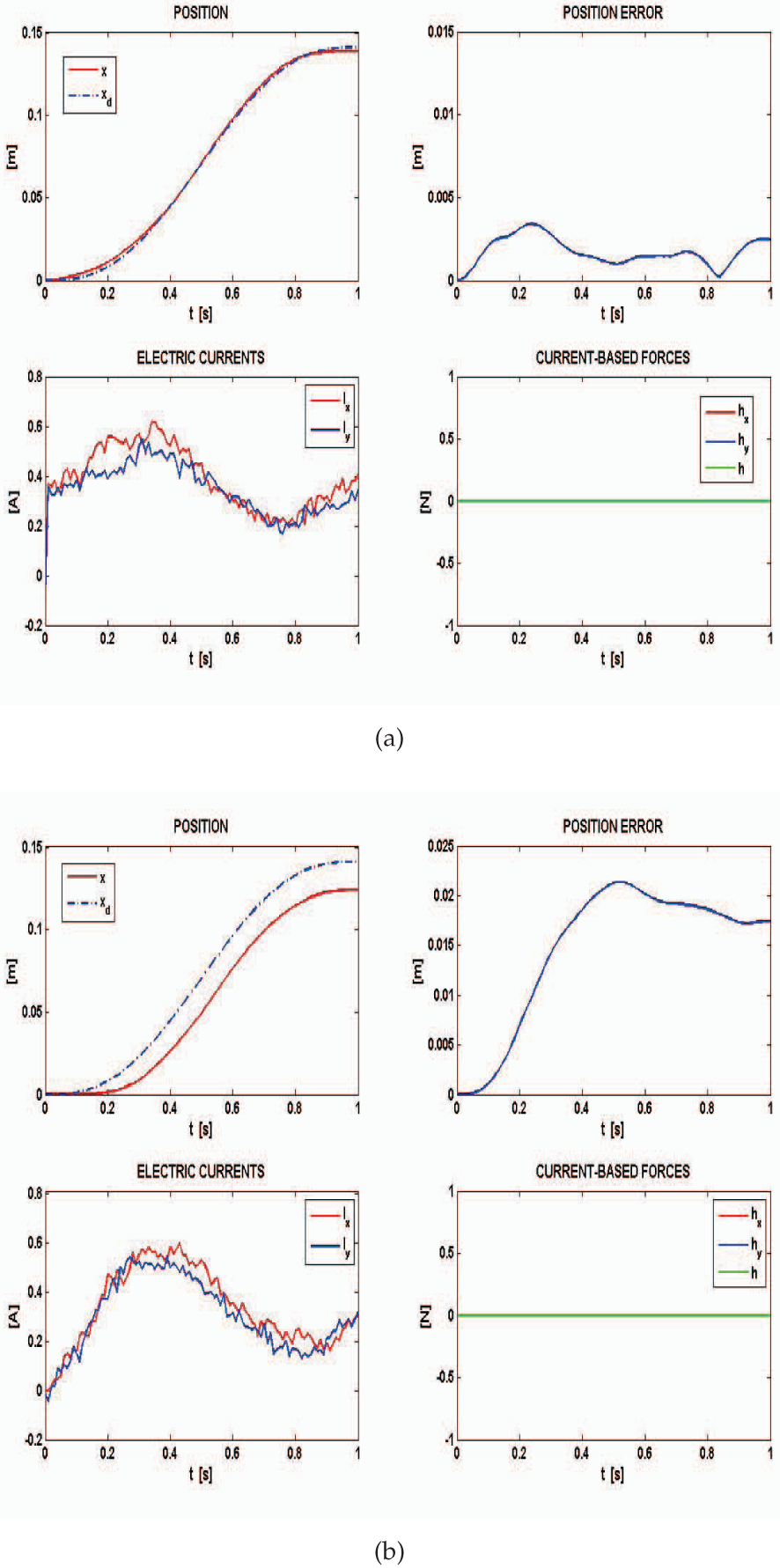
(a) Experimental results for motion tracking with friction compensation: desired and actual end-effector trajectories (top left), position error in norm (top right), recorded electric currents (bottom left), force values (bottom right). Control gains are KP = diag{100, 100} and KD = diag{10, 10}; (b) Experimental results for motion tracking without friction compensation: desired and actual end-effector trajectories (top left), position error in norm (top right), recorded electric currents (bottom left), force values extracted from currents (bottom right). Control gains are KP = diag{100, 100} and KD = diag{10, 10}.
This work demonstrated that current-based impedance control can solve issues related to the degradation of robot performance due to friction, thanks to inverse dynamics compensation, and tune the robot visco-elastic properties, thanks to indirect force measure through electric currents. Compliance regulation was achieved by tuning control parameters, thus achieving force values comparable to those measured on patients in previous clinical studies of robot-aided rehabilitation [54]. Current feedback can play a key role in force feedback and simplify gain tuning, by allowing the same set of PD gains (e.g. KP = diag{100, 100} and KD = diag{10, 10}) to be used in free as well as constrained space with a good level of accuracy (0.004 m is the peak of position error) and force regulation (h = 21.41 N is the peak of interaction force) for the addressed application. The control requires continuously carry out estimation procedures on static and dynamic friction and current threshold, because of their variability with environmental conditions. In our case, this was efficiently achieved by developing an initial robot calibration procedure (running every time the machine is turned on) that was able to automatically implement the friction identification procedure described in Sect. 4, and current threshold identification mentioned in Sect. 6. The calibration procedure is currently running during motion in the free space. It will be extended in order to account for a vertical weight (such as the patient arm) applied at the handle.

Experimental results for the current-based impedance control during a constrained task with 1 kg applied at the end-effector: desired and actual end-effector trajectories (top left), position error in norm (top right), recorded electric currents (bottom left), force values extracted from currents (bottom right). Control gains are KP diag{40, 40} and KD diag{4, 4} in (a) and KP = diag{100, 100} and KD = diag{10, 10} in (b).
This study provides evidence that an integrated approach between mechanics and control can help design Class II rehabilitation robotic machine with features comparable to Class I robots. The proposed interaction control strongly relies on the identification of a force-current relationship and is applied in this work to the robotic machine developed by the authors, which has a simple planar structure. However, it can be extended to more complex robotic structures with electric actuation by means of a multivariate regression analysis. Special care is required for redundant robots, where redundancy needs to be addressed by an inverse kinematics algorithm before applying the force-current characterization procedure. The use of electric currents to detect interaction offers the important benefits of (1) higher reliability than force sensors, notoriously characterized by significant noise; noise is lower in current readings with no need for low-pass filtering; (2) robustness, as the probability of damage to force sensors is higher than that for electric actuators. This is an important achievement in rehabilitation robotics, since it addresses a more general aim of enhancing robot dependability in human-robot interaction.
Future research will further validate the control with an extensive comparative analysis with other sensorless approaches proposed in the literature and finalize system behaviour for extensive use in clinical practice with neurological patients (such as chronic post-stroke, sub-acute post-stroke, brain injured patients). An application of the robotic system to tele-rehabilitation is finally envisaged.
Footnotes
14. Acknowledgement
The authors would like to thank DAS s.r.l., Palombara Sabina (Rome), Italy, for the fruitful collaboration in robot design and fabrication. This work was supported by the national project Industria 2015 - DAHMS (Distributed Architecture Home Modular Multifunctional Systems), CUP B85E10003020008.