
Abstract
The performance of the real-time dynamic force and torque compensation, flexible force interactive control, and the ability to compensate for the defect of the passive rehabilitation training are the important functions within the rehabilitation robot design process. In this investigation, the upper limb rehabilitation robot is designed, and the force sensor is used to measure the joint feedback torque with high precision, high sensitivity, and low cost. In the rehabilitation robot design process, the human–machine adaptability and lightweight flexible driving design are considered, and the static and dynamic moment detection performances of the driving joint are analyzed. Furthermore, the impedance control algorithm is used to control the force output of the single drive joint, and then the sinusoidal force output performance and step force output performance are tested under different amplitudes and frequencies. Finally, the passive rehabilitation mode of the prototype is tested to evaluate the performance of the rehabilitation robot. The results show that the force output accuracy and stability of the driving joint has a good performance, which can satisfy the force-assisted application of exoskeleton.
Keywords
Introduction
There are more and more patients with upper limb hemiplegia caused by stroke. Rehabilitation of the upper limb has been the important problem for hemiplegic patients in the world, and the motor dysfunction of upper limb leads to loss of self-care ability for these patients. 1 , 2 In practice, the clinical rehabilitation training of upper limbs mostly adopts exercise therapy which means long-term repeated exercise on the patient upper limbs by rehabilitation physicians, but the effect of rehabilitation is often influenced by rehabilitation doctors and various subjective factors.3,4
Rehabilitation robot, which is usually used in the rehabilitation training process, is just one of the medical tools, and therefore, its design and optimization would significantly improve rehabilitation efficiency for hemiplegic patients and reduce the burden of rehabilitation doctors. It is interesting to note that the rehabilitation robot has many requirements for hemiplegic patients, such as simple operation, high stability, and low cost.
Rehabilitation robots have been fully developed in the past decades. Mao and Agrawal 5 presented a 5-degree-of-freedom (5-DOF) exoskeleton rehabilitation robot, and rehabilitation training in a wide range of joints can be achieved by the force sensor within the wire rope. He et al. 6 designed a 4-DOF pneumatic muscle-driven exoskeleton rehabilitation robot, which had the advantages of lightweight and high-power quality ratio. The company of Hocoma 7 , 8 developed a 5-DOF exoskeleton rehabilitation robot, and it had the advantages in gravity compensation, enlarging the range of joint motion, and real-time monitoring of patients’ joint status. Perry et al. 9 designed a 7-DOF rope transmission exoskeleton rehabilitation robot, and it had the characteristics of high design flexibility, high stiffness, low inertia, and zero backlash.
Thus, it can be seen that the performance of driving joint is an important reference factor for evaluating the performance of rehabilitation robot. Kim and Deshpande 10 developed an active DOF upper extremity exoskeleton rehabilitation robot, in which each joint was driven by a series elastic actuator (SEA) and the force control of the whole exoskeleton was realized by the torque sensor. They also designed an experiment to observe the frequency response performance of joint output torque, which was measured by spring deformation. However, it has the disadvantage of large weight and poor force control effect. An exoskeleton rehabilitation robot had been developed by Hwang and Jeon, 11 in which the dynamic moment sensor was used to measure and evaluate human muscle moment, and meanwhile, the torque sensor was applied to detect the output torque through micro-deformation. It has a good dynamic performance, fast response, and high detection accuracy, but its application in exoskeleton is limited with its large volume and mass. Capurso et al. 12 presented a rehabilitation robot without force sensor, force and moment sensors were not installed in the each joint, and then the Kalman filter method was used to monitor the current and estimate the joint moment value. The force compensation effect is remarkable, and the system is simple. However, the compensation accuracy of this estimation algorithm still needs to be improved, and its detection is invalid under the condition of zero speed.
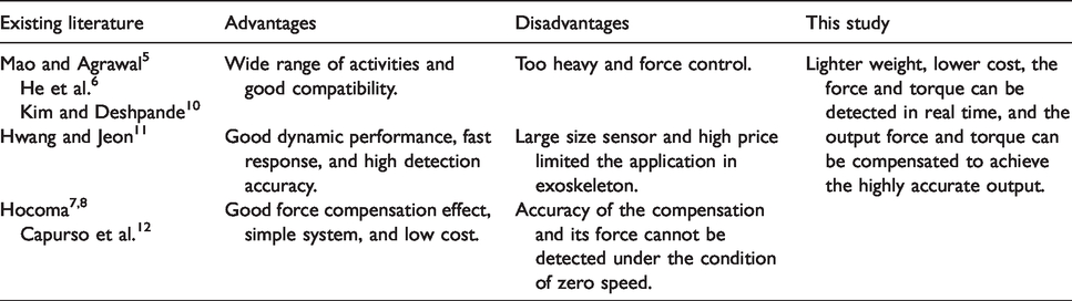
According to the comprehensive analysis of the current joint design of rehabilitation robot, there are still many problems to be solved urgently in upper extremity exoskeleton rehabilitation robot. In this investigation, the man–machine adaptability and lightweight flexible drive design are considered in the rehabilitation robot design process, and the static and dynamic moment detection performances of the driving joint are analyzed from converting the tension value and pressure sensor into the moment value. Furthermore, the impedance control algorithm is used to control the force output of the single drive joint, and then the sinusoidal force output performance and step force output performance are tested under different amplitudes and frequencies. Moreover, the passive rehabilitation mode of the prototype is tested to evaluate the performance of the rehabilitation robot. The main differences between proposed prototype in this study and existing literature are shown in Table 1.
Main differences between proposed prototype in this study and existing literature.
Design methods and principles
Selection of joint freedom and angle
The choice of joint freedom and angle is related to the rehabilitation training range of rehabilitation robot. The larger the range of joints, the more training model the rehabilitation robot provides, but it is more complex. Kinematics analysis of human upper limb joints shows that scapula and clavicle cooperate with each other when the shoulder joints are extensively extended. This is due to the fact that the shoulders are swing back and forth, meanwhile, the center of rotation is float up and down with 5 DOFs. Therefore, the design of 5-DOF shoulder exoskeleton has better compatibility with human shoulder joint. However, the 5-DOF shoulder joint is very complex, and the coordinated movement of scapula and clavicle with upper limb is difficult to be replaced by mechanical movement. Moreover, three distal joint movements associated with the forearm and wrist joints increase the burden on the upper limb root actuators. According to the characteristics and power–mass ratio of various actuators, this layout reduces the ability of the robot to assist the shoulder and elbow joints. Therefore, the joint angle should be selected by considering the safety, mechanical characteristics, and symptoms of hemiplegic patients. The main reference points are as follows:
Hemiplegic patients need only part of the normal range of functional activity training. Due to the fact that the excessive deviation of the rotation center of the shoulder joint leads to patient discomfort and injury, thus the shoulder joint with 3 DOFs should not have extensive extension. When shoulder abduction occurs, robot should avoid collisions with human heads. During rehabilitation training, the manipulator arm avoids collision with the trunk. Considering the safety factors, mechanical hard limit and program soft limit should be adopted to limit the range of structural activity within a reasonable range.
Dimension parameters of upper limb
The compatibility of different patients should be considered in the size selection of rehabilitation robot. Considering the safety and health of human body, P99 and P1 are selected as upper and lower limit size of the rehabilitation robot. These sizes can be used for 98% of the population. 13 The human body sizes of male and female are listed in Tables 2 and 3, repectively. 14 , 15 According to Tables 2 and 3, the dimensions of exoskeleton robots should be followed are shown in Table 4.
Measurements of males aged 18–55 years.

Measurements for females aged 18–55 years.

Adaptation dimensions of robots.

Considering the safety and health of human body, P99 is chosen as the reference value of the upper limit of size, which means that these rehabilitation robot sizes can be used for 99% population. The size of the adaptation is shown in Table 5. According to Table 5, the diameter of the upper arm and forearm bandage is 121 mm, since the size of the upper arm circumference and forearm girth is similar. In order to be easy to wear and adapt to different sizes of hand, the inner diameter of the grip is designed as 95 mm.
Adaptation dimensions of robots.

Joint torque and velocity factor
Joint moment and velocity are important parameters to evaluate the performance of driving joint. Table 6 shows the basic torque and speed parameters for the shoulder and elbow joints.
Auxiliary torque and speed of shoulder and elbow joints.

Structural design of the whole machine
Figure 1 shows the structure of the upper limb rehabilitation robot. There are 4 DOFs in each side, including 3 DOFs in the shoulder and 1 DOF in the elbow. The single joint drive unit is adopted in each joint drive mechanism. In fact, different patients have different body sizes; thus, the length of shoulder joint, arm, and forearm can be adjusted. In order to fix the patient conveniently, a strapping device is installed in the middle of the upper arm and forearm, and a grip is arranged on the end of the forearm. A control box is arranged on the back to install controllers, drivers, and related electronic components. The integral device is mounted on the mobile car and its height is adjustable. Overall, the mobile rehabilitation robot is easily adapted to rehabilitation training of different heights and postures.

The overall structure of the upper limb exoskeleton.
Design of single joint structure
According to the actual demand, the single joint module of the rehabilitation robot should have the capability of force interaction control, and can be used to provide enough auxiliary force. The joint assistant moment and velocity range for major joints of hemiplegic patients are shown in Table 6. Since the requirements of moment and speed of each joint are similar, the same size of the actuator is applied from the idea of modularization.
The SEA is chosen as the driving unit, the macroscopic deformation of elastomer is detected by encoder, and then the output torque is measured. As shown in Figure 2, the drive component is composed of a direct current (DC) brushless motor and a harmonic reducer through the adapter disk, which is fixed on the connecting rod of the adjacent joint. Harmonic reducer and load connecting rod rotate coaxially. The output link of the reducer and the fixed block of the sensor are connected with the tension pressure sensor in series; thus, the force and moment feedback of the joint output can be obtained. For the sake of safety, the mechanical stop block is arranged to prevent the rotating joint from overrunning.
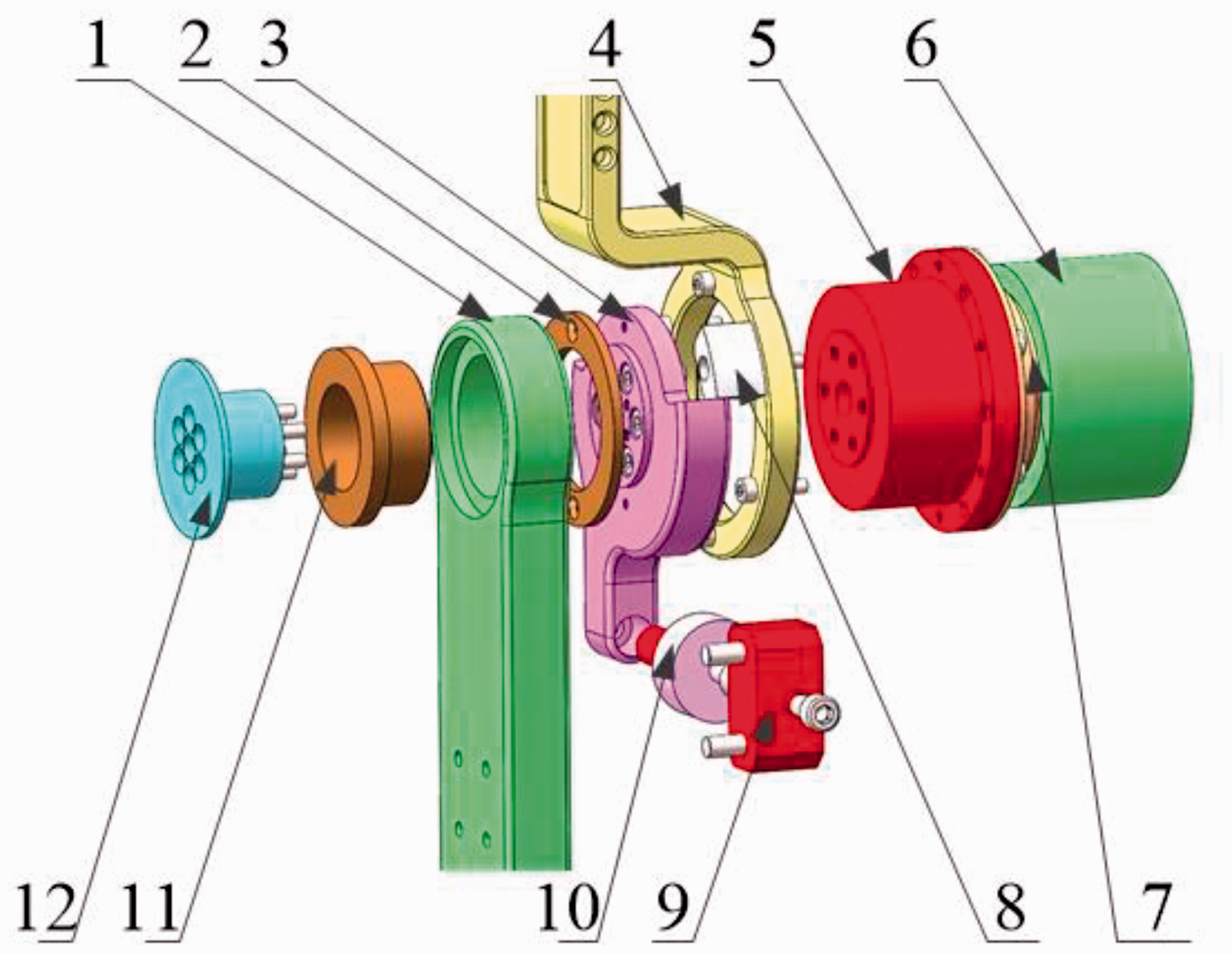
Three-dimensional view of single joint structure.
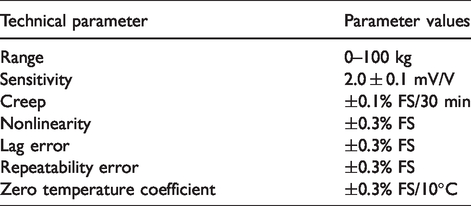
In order to reduce the weight and control performance of the rehabilitation robot, the DC brushless motor and harmonic reducer are selected in the drive system, and the tension–compression sensor is selected. Although the performance of the tension–compression sensor is slightly poor, it satisfies the requirements of the drive system. The tension–compression sensor parameters are shown in Table 7. The kinematic performance parameters of the single joint are shown in Table 8.
Technical parameters of tension–compression sensor.
Single joint motion performance parameters.

Experimental test and analysis
In the process of rehabilitation, the single joint output torque of rehabilitation robot is divided into static torque, dynamic torque, sinusoidal torque, and step torque. In this section, the response performance of single joint to them needs to be tested in turn. Finally, the passive rehabilitation performance of the whole machine is tested.
Joint static torque detection
As shown in Figure 3, the elbow joint is in a horizontal state, the motor shaft is in a mechanical locking state, the electronic dynamometer is fixed under the vertical skeleton of the forearm, and the serial line under the dynamometer is connected to the computer so that the dynamometer can read the load data in real time. Based on the above arrangement, load data and force sensor measurement data can be read and compared simultaneously to verify the effectiveness of joint moment detection. The different fixed loads are applied on the electronic dynamometer, and the parameters of dynamometer and force sensor are collected and converted into torque. The results are shown in Figure 4.

Method of torque detection.

Static torque test.
From Figure 4, it can be seen that the actual error and measurement error of static load moment are less than 1.5%. When the moment is large, the error increases obviously. Due to the fact that the error source from the processing accuracy of mechanical structure and the small deformation of parts after loading, this error is normal in the measurement process.
Joint dynamic torque detection
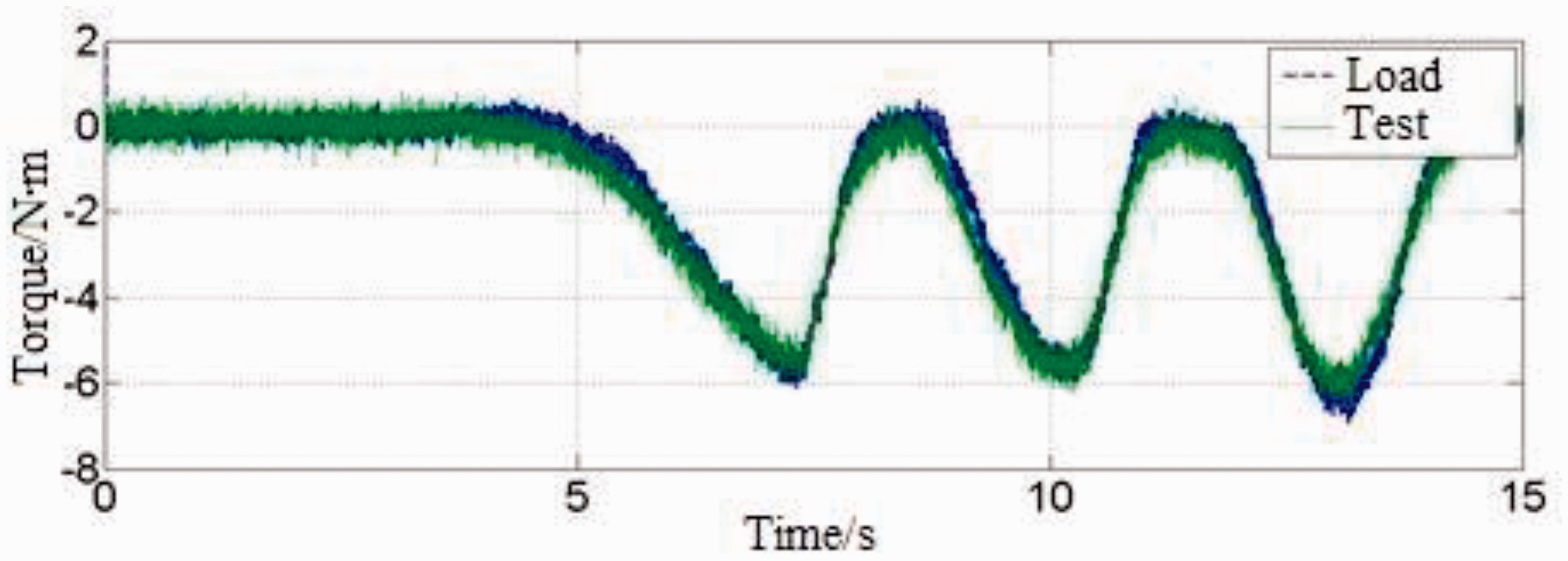
To verify the validity of single joint dynamic moment detection, the dynamic load is applied manually and randomly by an electronic dynamometer at the beginning of the test. At the same time, the load torque curve of the electronic dynamometer and the measurement moment curve of the force sensor are obtained. Figure 5 shows the measurement results. The difference curves between the measured moment and the load moment are shown in Figure 6.
Dynamic torque curve.

Dynamic torque difference curve.
From Figure 5, it can be seen that the dynamic measurement moment basically reflects the dynamic load moment, and the difference is very small. From Figure 6, the dynamic moment errors are very small in most states, but the dynamic moment errors increase significantly when the part of the load is large or change quickly.
Joint sinusoidal torque output response test
The single joint force control performance has a great influence on the rehabilitation training of patients. In this investigation, the driving joint force control experiment is carried out to test the single joint force control performance, as shown in Figure 7. The joint fixing rod is fixed on the base, the load rod is connected with the dynamometer, and the dynamometer is fixed on the base. The control of driving joint motor and the acquisition of force sensor signal are realized by ARM and FPGA. ARM and FPGA are monitored by personal computer (PC) in real time. The measured value of dynamometer is transmitted to PC through serial port line.

Schematic diagram of joint test system.
The test parameters are set as sinusoidal reference curve, and the reference amplitudes of the curves are (±5 N m) and (±10 N m) moments with frequencies of 1, 0.5, 0.25, and 0.125 Hz, respectively. The response bandwidth of the force sensor is 1 kHz. As shown in Figure 8, it can be seen that some vibration occurs during the start-up stage of the experiment, and then it enters the steady state. After entering the steady state, the maximum error is controlled in the range of (±1 N m). Moreover, it can be observed that there are obvious differences in tracking performance under tension and compression, the error range is less than 1 N m at the tension stage, and the error range is less than 0.5 N m at the compression stage. By comparing the experimental data of different groups in Figure 8, it can be found that the tracking effect is better with the decrease in the moment frequency, and the error is smaller, which is consistent with the basic facts. With the increase in the moment amplitude, the error increases, but the error ratio decreases gradually. When the amplitude of the curve is 10 N m and the frequency is 0.125 Hz, the error rate is less than 3%.

Sinusoid torque responses under the different operating conditions.
Output response test of joint step torque
The joint fixing rod and output rod are fixed, and the step moment of 0–5 N m is selected as the initial reference value. The response bandwidth of the force sensor is 1 kHz. The results are shown in Figure 9; the joint output response occurs fluctuation 2 N m in the initial stage, which tends to be stable within 1 s. Therefore, single joint has better response performance to step moment.
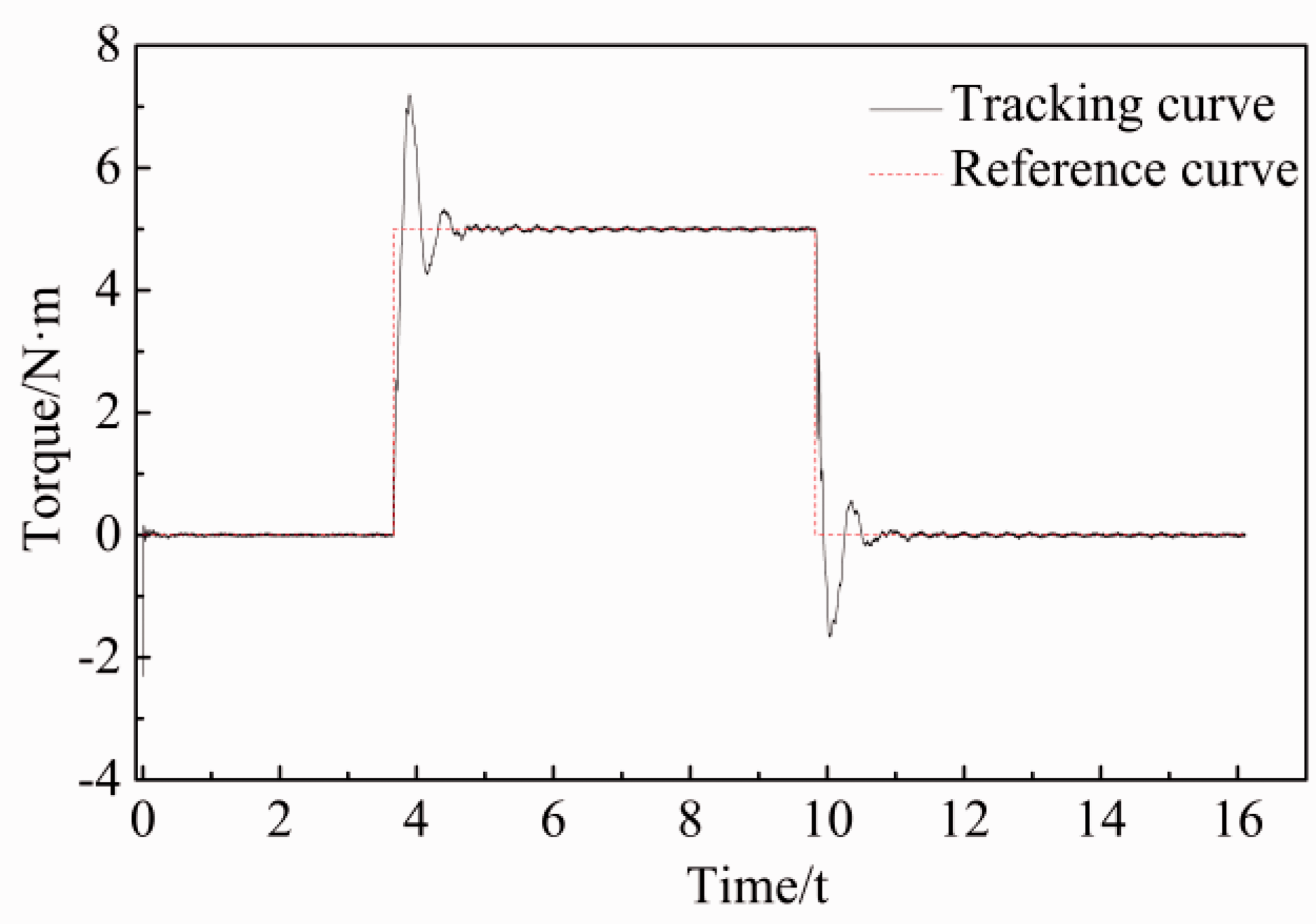
Step torque responses.
Whole machine passive rehabilitation test
Before the start of the experiment, the human body size is measured, and then the size of the corresponding parts of the exoskeleton is adjusted to facilitate the fixing of the upper arm and forearm of the human body. Finally, the human body can relax its upper limbs naturally.
In the process of rehabilitation, different rehabilitation exercises have different exercise cycles. In this article, the motion cycle of each joint is distinguished and tested. The following exercises are performed on the right four joints: the position curve of joint 1 is a sinusoidal curve with an amplitude of π/5 and a period of 8 s; the position curve of joint 2 is a sinusoidal curve with an amplitude of π/5 and a period of 7.5 s; the position curve of joint 3 is a sinusoidal curve with an amplitude of π/4 and a period of 10 s; and the position curve of joint 4 is a sinusoidal curve with an amplitude of π/3 and a period of 9 s. The right exoskeleton velocity error curve is shown in Figure 10, and the position error curve is shown in Figure 11.
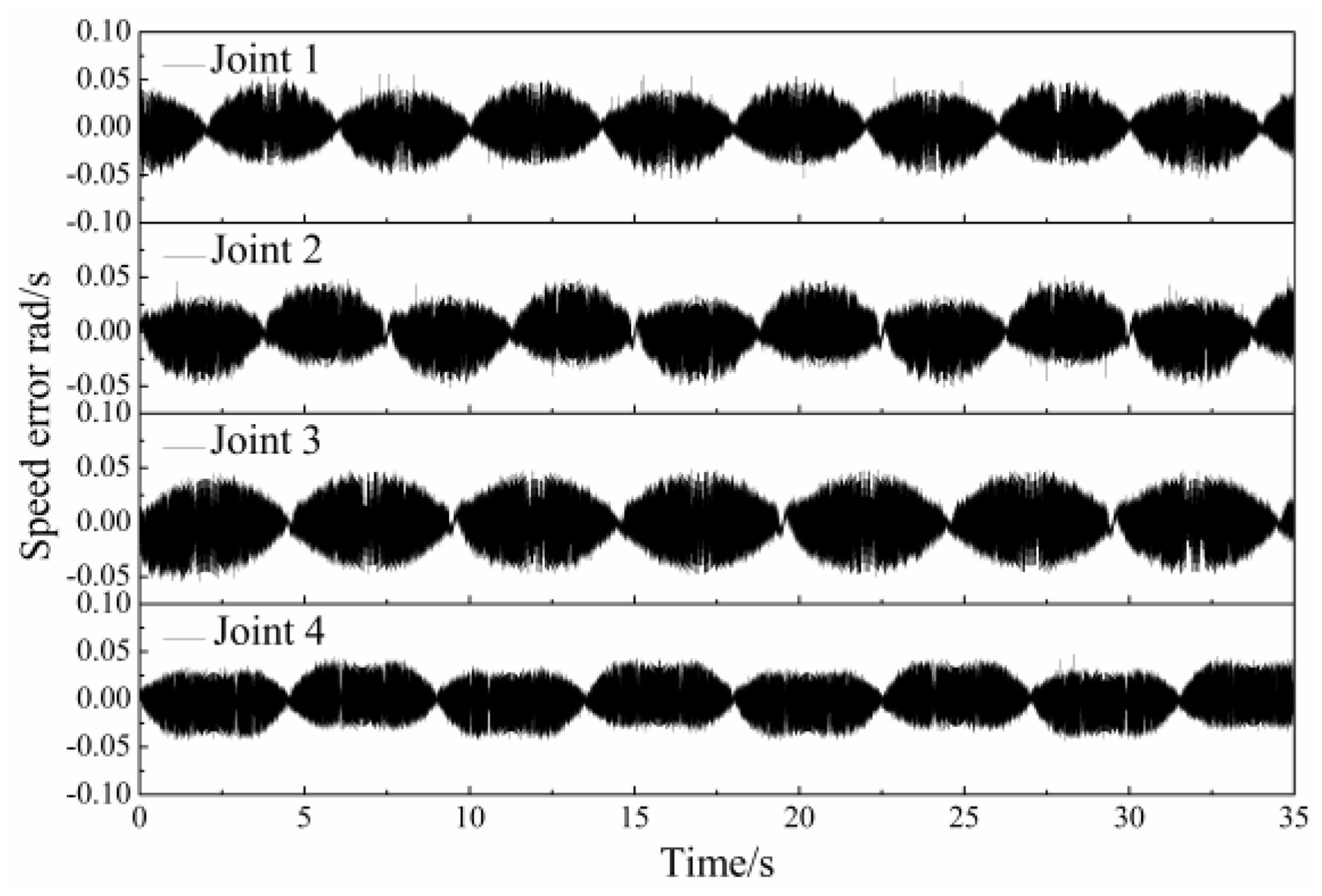
Velocity errors of joints.

Positional errors of joints.
According to Figures 10 and 11, the velocity and position tracking curves of the right exoskeleton joint show good tracking accuracy, and the performance of the passive training mode is stable. At the same time, the joints of the human body can stretch naturally without obvious pain and discomfort, and the upper arm and forearm bandages can be effectively fixed.
Conclusion
It can be seen from the results and discussion above that:
The experimental results show that with the decrease in torque frequency, the force sensor tracking performance is getting better and the error is getting smaller. With the increase in torque amplitude, the error increases, while the error rate decreases. Under the condition of amplitude 10 N m and frequency 0.125 Hz, the error is within 3%, which means that the structure satisfies the actual requirement. The speed tracking curve and position tracking curve show good tracking accuracy, and the performance of passive training mode is very stable. During the passive rehabilitation test process, the patient’s joints have the ability of stretch naturally without obvious pain and discomfort.
It was, therefore, concluded that the driving joint design in this article has the potential to be used in rehabilitation robots. The proposed design method in this article can combine some modeling and estimation algorithms16–17 to study the model-based predictive control approaches of different dynamic systems such as rehabilitation robots.
Footnotes
Handling Editor: James Baldwin
Declaration of conflicting interests
The author(s) declared no potential conflicts of interest with respect to the research, authorship, and/or publication of this article.
Funding
The author(s) disclosed receipt of the following financial support for the research, authorship, and/or publication of this article: This research was financially supported by the China National Science Foundation (project no. 61603127) and the Natural Science Foundation of Hubei Province (project no. 2016CFB513).