
Abstract
A bedside rehabilitation robot is developed to address the challenge of motor rehabilitation for patients with lower limb paralysis. Firstly, based on the principles of physical rehabilitation, a two-link planar robot model is used to simulate both the robot and human lower limbs, and the coupling characteristics between the human and robot are thoroughly analyzed. Then, the lower limb rehabilitation robot, fitted with an end-effector and ankle wearable feature, is designed according to the structural parameters. To enhance patient safety during rehabilitation, the device incorporates a freely rotating leg support mechanism that reduces the load on the ankle due to gravitational forces, and a two-stage series elastic mechanism is integrated below the foot support to provide a passive compliant output of robot power, allowing for more natural movement and reducing the risk of injury. Secondly, dynamic modeling is used to determine the dynamic parameters of the robot by conducting simulation calculations based on the inertia parameters of the human body and the robot model design parameters. Finally, an experimental platform is established using the structural and dynamic parameters, and the robot’s reliability is validated through experimentation. Results indicate that the robot can accurately complete passive rehabilitation training tasks, and the dynamic parameters meet the expected requirements.
Keywords
Introduction
Lower limb paralysis has become increasingly prevalent in recent years due to frequent occurrences of strokes and traffic accidents. Strokes, a common clinical disease, have shown a trend of increasing prevalence in recent years. The disease is life-threatening in the early stages of its onset, and with the development of medical care, the mortality rates have been decreasing significantly and the survival rate is increasing, but many survivors will suffer from lower limb paralysis. 1 According to neuroplasticity, the post-stroke rehabilitation process is divided into three main phases: acute, subacute, and chronic, of which the acute phase has the best rehabilitation effect. 2 The subacute phase is the most effective, but it is also the most difficult phase to treat. 3 Comprehensive rehabilitation is required during the chronic phase, especially for the lower extremities, as it determines the patient’s quality of life. Traditionally, rehabilitation treatments require a physiotherapist to help patients perform motor function training. The rehabilitation effect is determined by the physiotherapist’s clinical experience and operation technique, leading to high costs for rehabilitation. Furthermore, this method of rehabilitation requires significant physical effort and effort from the therapist and can be a painful process for the patient, often requiring the therapist to provide guidance and psychological support to achieve optimal rehabilitation outcomes.
Rehabilitation robots are a product of interdisciplinary collaboration between various fields, including robotics, rehabilitation medicine, and sensor technology. These robots have been developed to aid in the rehabilitation training of limb motor functions. Advances in this area have led to the creation of numerous lower limb rehabilitation robots that have been successfully applied in clinical settings. These applications have been widely recognized by both patients and doctors, with some studies showing very good rehabilitation outcomes achieved by utilizing these rehabilitation robots. 4,5
Lower limb rehabilitation robots can be classified into two main types: wearable and end-effector, based on their coupling form with the human lower extremities. Wearable robots are primarily designed to restore the patient’s gait and need to work with weight reduction systems, such as LOKOMAT, 6 ALEX, 7 and LOPES. 8 Some wearable lower limb rehabilitation robots are designed in a sitting or lying position, such as MotionMaker, 9 iLeg, 10 and RECOVER. 11 End-effector lower limb rehabilitation robots achieve rehabilitation by exerting traction on the soles of the feet or ankles. For example, Haptic-Walker 12 and Bo et al. 13 guided the patient’s ankle for motor rehabilitation using a Stewart parallel robotic platform in the standing position. Traction rehabilitation is necessary when the patient is in a supine position, especially in the early stages of rehabilitation of stroke patients, where the affected limb is weak and unable to stand. NEUROBike 14 is one of the end-effector lower limb rehabilitation robots developed for patients in the supine position. The device features two linear guides that pull the sole of the foot in the sagittal plane, a rotary motor at the end that allows for ankle abduction and adduction, and a pulley frame to lift the knee joint and maintain the correct position during rehabilitation. The pulley frame also reduces the weight of the lower limb, which helps prevent ankle injury. ViGG 15 is a four-degree-of-freedom robot that pulls the sole of the foot through the end, and it is allowing the trajectory to be planned according to height and weight characteristics. In addition, some rehabilitation devices 16,17 achieve lower extremity rehabilitation by using a rope to provide traction to the ankle. These devices take advantage of the flexibility of the rope, making the rehabilitation process safer.
Based on an extensive literature review, it has been determined that the ankle is the most effective point of traction for lower limb rehabilitation in patients lying in a supine position. In addition, support or weight reduction is necessary for the lower leg to prevent excessive strain on the ankle joint during rehabilitation. To address these needs, this article presents a novel four-degree-of-freedom bedside lower limb rehabilitation robot. The robot not only facilitates rehabilitation training in the sagittal plane of the lower limb but also enables abduction and adduction of the ankle by supporting the lower leg to reduce strain on the ankle joint. Furthermore, the sole of the foot is equipped with elastic support to protect against the impact of robot motion during therapy. To ensure optimal human–robot coupling, a customized lower limb rehabilitation motion trajectory planning method is designed based on human joint motion angles, enabling the robot’s motion trajectory to conform to the natural human movement pattern. In addition, power parameters for the robot are optimized and designed according to the dynamics model to meet the power requirements of the human-robot interaction.
The second section of this article presents the specific structure of the lower limb rehabilitation robot. The third section presents the human–robot coupling motion characteristics. The fourth section presents the dynamics modeling of the robot and human lower limb. The experiments and results are displayed in the fifth section, followed by conclusions in the second section.
Structural design of lower limb rehabilitation robot
As shown in Figure 1, the lower limb rehabilitation robot has four rotary joints that are driven by servomotors. The motor output is transmitted via a timing belt to the harmonic reducer, excluding of the first joint. The first and second links are of equal length, the third link is an L-type link, facilitating convenient placement of the fourth rotary joint, which is independent from the other three joints. In addition, the robot includes a leg support mechanism and a footrest, with a passive compliant mechanism designed between the footrest and the fourth joint. The incorporation of a passive compliant mechanism featuring two degrees of freedom in the robot is intended to reduce discomfort and minimize strain for patients undergoing rehabilitation. Overall, these design elements facilitate improved rehabilitation outcomes while optimizing patient comfort.
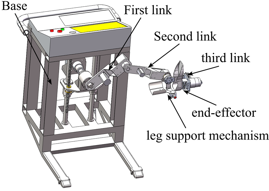
The 3D model of lower limb rehabilitation robot.
The passive compliant mechanism of the rehabilitation robot is composed of two stages in series: the sagittal-axis-guided spring and the crown-axis-guided spring, as illustrated in Figure 2. The first stage of sagittal-axis-guided springs comprises four groups, which ensure the stability of the spring compression direction by means of sliding bearings. This design element prevents spring compression inability resulting from friction with the guiding axis. Since the foot is secured to the footrest with straps, the impact of the robot on the lower limb occurs in a unidirectional manner in the sagittal plane. Therefore, all first-stage springs are unidirectional compression springs. In contrast, the second-stage coronal-axis-guided springs consist of two groups, each group with two unidirectional compression springs arranged on both side of the middle flange. When the intermediate flange slides along the coronal-axis guide, one side compresses while the other uncompressed. During ankle joint adduction and abduction movements, the fourth joint output force is passively compliant output through the second-stage spring. Meanwhile, the robot achieves passive compliant force output through the first-stage spring during hip, knee and ankle flexion and extension movements.

Exploded view of the elastic cushioning mechanism. 1 – footrest, 2 – footrest flange, 3 – crown shaft guide rod and bilateral spring, 4 – intermediate flange, 5 – sagittal shaft guide rod and spring, 6 – fourth joint output flange, 7 – fourth joint harmonic reducer and fixing plate.
Human–robot coupling motion characteristics research
Human lower limb kinematics and workspace
The lower limbs play a critical role in human movement, and the hip, knee, and ankle joints are widely recognized as key points for rehabilitation physiotherapy. As such, research efforts related to lower limb rehabilitation robots have tended to focus on these three joints. In this article, we homed in on the flexion and extension movements of the hip, knee, and ankle joints. More specifically, we modeled the kinematics of the human lower extremity by treating the thigh as the first link and the hip as the first rotational joint. Subsequently, the calf was regarded as the second link, with the knee joint acting as the second joint, and the foot as the third link, with the ankle joint serving as the third joint. By using this approach, we were able to conceptualize the human lower limb as a three-link plane robot. Consequently, we were able to derive the following kinematic equations 18

where l
1, l
2, and l
3 denote the lengths of the first, second, and third links;
Careful observation of physical rehabilitation therapy conducted by a therapist with a patient in a supine position reveals that the flexion and extension of hip and knee joints can be achieved more effectively through traction on the ankle. Often, the therapist will usually hold the ankle with one hand and the foot with the other hand while performing ankle flexion and extension exercises. This approach is preferred due to the anatomical structure of the ankle joint. The joint is composed of the talus and tibiofibular, resembling a mortise and tenon construction capable of withstanding substantial pressure but not too much tension. Therefore, traction applied to the foot can lead to ankle dislocation, making traction on the ankle is a more viable option when designing a lower extremity end-effector rehabilitation robot. This means that only the kinematics of the thigh and calf need to be considered, so that the lower extremity kinematic model can be simplified into a two-link model, as follows

The workspace of lower limbs can be obtained from the simplified kinematic model. To this end, we used human dimensions standards 19 and selected the male body dimensions with a male percentile of 50 in the 18–60 year-old age group. Specifically, we selected a thigh length of 0.465 m and calf length of 0.369 m. The range of joint movement was determined based on the normal human lying posture, and the relevant details are shown in Table 1. Utilizing this pertinent information, we then analyzed the lower limb workspace using the Monte Carlo method. Through this analysis, we were able to obtain the human lower limb workspace, which is presented in Figure 3.
Range of motion for flexion and extension of each joint of the lower limb.


Human lower limb workspace. A two-link model represents the thigh and lower leg, where the blue link represents the thigh and the red link represents the lower leg. The origin of the model is on the axis of the hip.
In our human model, we have defined the distance between the ankle joint and the sole of the foot as the third link. This distance can be calculated by determining the difference between the height of the tibial point and the length of the lower leg. In the case of the male percentile of 50 within the 18–60 year-old group, data from human dimensions standards 18 indicate that this distance is 0.075 m (The human tibial point height for the male percentile of 50 in the 18–60 years group is 0.444 m and the calf length is 0.369 m, which yields 0.075 m from the sole of the foot to the ankle joint), which is significantly smaller than the length of the lower leg. Based on this observation, we can conclude that the flexion and extension movements of the ankle joint can be treated as independent movements. Therefore, it is possible to design a separate rotation mechanism for the ankle joint, which can be operated either independently or in conjunction with the hip and knee joints. This approach can be effectively utilized in the design of lower limb rehabilitation robots.
Design of robot structural parameters based on human–robot coupling motion analysis
The human–robot coupling structure of the end-effector lower extremity rehabilitation robot is relatively simple, but it is important to consider the position relationship between the patient and the robot. To achieve an optimal overlap between the robot end-effector and the human ankle, we have designed a two-link series robot model wherein the two links are of equal length. This design ensures that the workspace of the lower limb is completely covered, and the robot’s workspace is maximized. Considering that the robot will be placed next to the bed and the robot’s workspace is planar, we have chosen point A (in Figure 3, at this point the knee is flexed −120° and the hip is extended 90°) as the origin for the robot’s base coordinate frame and have calculated the coordinates of this point for the smallest person dimensions using the parameters outlined in human dimensions standards 18 for the female group aged 18–55 with percentile 1. Here, the thigh length was determined to be 0.387 m and the calf length was 0.3 m, yielding coordinates of point A as (0.2598, 0.237). Based on these calculations, we have determined that the distance of the robot’s base coordinate origin from the human hip joint can be set at 0.26 m in the horizontal direction and 0.23 m in the vertical direction. These values will ensure that the rehabilitation training is optimized for patients of varying heights and will facilitate effective and efficient rehabilitation outcomes.
After determining the base coordinate frame relationship between the human–robot model, calculating the link length for the robot becomes easier. Since the robot is placed on the side of the bed, the first link cannot move under the bed, restricting the range of motion of the first joint angle of the robot to [−20°,180°]. In addition, the second joint should be limited to [−180°, −5°]. To determine the workspace of the robot and the human lower limb model, we have used the Monte Carlo method, as shown in Figure 4. The robot’s workspace in the figure completely covers the workspace of the lower limb model. The total length of the robot’s link should be greater than or equal to the lengths of its base coordinate origin (approaching point A at (0.26,0.23)) to the upper and lower right corner points in Figure 3. The upper corner point represents 90° hip flexion and 0° knee flexion, whereas the lower right corner point represents 0° hip flexion and 0° knee flexion. We determined the length of the thigh to be 0.465 m and the length of the lower leg to be 0.369 m. From point A to the upper corner point, the distance was calculated as 0.703 m, while the distance to the lower right corner point was 0.527 m. Therefore, the length of the robot link is 0.36 m, and the total length of the link is 0.72 m, which is greater than the distance from the origin to the upper corner point and the lower right corner point of the lower limb model movement space.

The two-link series robot model workspace and human lower limb model workspace. The red presents lower limb model workspace, and the blue presents robot model workspace.
To facilitate effective plantarflexion–dorsiflexion motion of the ankle joint, a rotational joint is added to the end of the second link of the robot. To ensure the coupling of the third rotational joint of the robot with the ankle joint of the human body, it is necessary to design a leg support mechanism. Regarding the adduction and abduction motion of the ankle joint, which occurs in the coronal plane, unlike the plantarflexion–dorsiflexion motion, which occurs in mutually perpendicular planes, these two motions are independent of each other. Consequently, another rotational joint is tandemly connected to the third link of the robot. Importantly, this additional rotational joint should be designed such that its motion plane is perpendicular to that of the third link motion plane. So, we can get a four-degree-of-freedom lower limb rehabilitation robot.
From the above analysis, it is clear that the first and second rotary joint of the lower limb rehabilitation robot resemble a planar two-link robot, which facilitates the flexion and extension movements of the human lower limb’s hip and knee joints through ankle traction. In contrast, the other two rotary joints are analogous to a wearable ankle rehabilitation robot, whereby the foot is fastened to the output end of the fourth rotary joint with straps. The third rotary axis is designed to coincide with the plantarflexion–dorsiflexion axis of the ankle. To maintain the above axes’ coincidence during the exercise, a leg support mechanism is devised such that it is free to rotate. The rotation axis of this mechanism coincides with the third rotation axis, enabling it to reduce the pulling force applied to the ankle by the leg’s weight while in the supine position. Moreover, the leg support mechanism protects the ankle joint during rehabilitation process, allowing for independent and effective rehabilitation of the ankle joint consistent with the rehabilitation techniques prescribed by rehabilitation physiotherapists.
The length of the third link in the lower limb rehabilitation robot is primarily determined by the distance between the ankle and the sole of the foot. As previously mentioned, human dimensions standards 18 provide guidelines for determining this distance, which ranges typically between 0.064 m and 0.079 m. It is noteworthy that this distance does not vary substantially among individuals of different heights, thus making 0.08 m a reasonable design standard. Therefore, we have selected an ankle-to-sole distance of 0.08 m as the design standard for the lower limb rehabilitation robot’s third link length.
Passive rehabilitation motion trajectory planning
Rehabilitation robots are increasingly being developed as a means of supplementing or replacing the intervention of physical therapists to facilitate the rehabilitation process for patients. This type of training is commonly referred to as passive rehabilitation training. To ensure effective and efficient rehabilitation training, rehabilitation robots must be designed to customize a suitable motion trajectory based on each patient’s lower limb joint movement abilities. By adapting the motion trajectory in this manner, the rehabilitation robot minimizes any discomfort and distress caused to the patient, thereby enhancing the overall quality of the rehabilitation program for the lower limbs. It is worth noting that the tailored trajectory design should take into account the patient’s unique physiological characteristics and medical history, as well as their specific rehabilitation goals. Therefore, the development of an appropriate motion trajectory for rehabilitation robots is critical to achieving optimal rehabilitation outcomes for patients.
The analysis of human–robot coupling motion has revealed that the hip and knee joint’s flexion and extension motion are related to the fore two joints’ motion in the robot. Similarly, the ankle’s flexion/extension and the adduction/abduction movement correspond to the latter two joints’ motion in the robot. To illustrate this relationship, Figure 5 presents link models of the human lower limb and the lower limb rehabilitation robot. The lower part of the figure illustrates the human lower limb link model, while the upper part shows the robotic link model. It is interesting to note that the third link of the robot overlaps with the human foot’s link model, emphasizing its critical role in the rehabilitation process. Through this coupling analysis, we can design the robotic motion trajectory to mimic the natural movement pattern of the human lower limb effectively. This approach leads to better rehabilitation outcomes, as the rehabilitation robot’s movements can closely match the physiological characteristics of the human body.

Sketch of human–robot coupling relationship. The black links present lower limb model, and the blue links present robot model.
To concise the coupling motion between the human lower limb and the rehabilitation robot, it is necessary to establish two base coordinate frames: {O2} for the robot model and {O1} for the human lower limb model. The origin of {O2} is set on the axis of the first rotational joint of robot, while the origin of {O1} is set on the hip joint rotation axis of human model. The coordinates of any point in the two coordinate frames are related via a specific coordinate transformation determined in the previous section. This transformation enables the precise determination of the position and orientation of each point relative to the corresponding coordinate frame. The coordinate relationship between any points in the two coordinate frames can thus be expressed

where (x 1,y 1) is the point in the coordinate frame {O1} that lies in the XY plane; (x 2,y 2) is the point in the coordinate frame {O2} that lies in the XY plane.
Inverse kinematic solution of the robot model

where (x
2,y
2) denotes the position of the third rotational joint axis in the robot base coordinate frame;
Inverse kinematic solution of the human model

where (x
1,y
1) represents the position of the ankle in the body base coordinate frame;
The ankle plantarflexion–dorsiflexion motion angle is denoted by

The angle of the ankle joint adduction and abduction is equal to the rotation angle of the fourth joint of the robot. Considering that the movements cannot be performed simultaneously with the hip and knee flexion and extension movements during rehabilitation training, the rehabilitation robot generally controls this joint alone. Since the third and fourth joints are like the wearable ankle rehabilitation robot, the simultaneous movement of both joints will make the ankle rehabilitation more flexible without increasing the design difficulty of the robot.
In the passive rehabilitation training, the rotation angles of the hip and knee joints of the lower limbs can be set first, and the positions of the human ankle joints under the base coordinate frame of the human model can be obtained through the positive kinematics of the human lower limb model (equation (2)), and the rotation angles of the first and second joints of the robot can be obtained through the coordinate position transformation (equation (3)) and then according to the robot inverse kinematics (equation (4)). When the hip and knee joints need to be trained, the ankle joint angle needs to be substituted into equation (6) to obtain the motion angle of the robot’s third joint, regardless of whether the ankle joint performs plantarflexion dorsiflexion motion. This is because the robot third joint angle needs to change in real time so that the ankle can be in the set state. Due to the human–robot coupling characteristics, this forward and inverse kinematic trajectory planning by two models makes the robot motion trajectory completely in the reachable range of the lower limb motion, which ensures the safety of the rehabilitation movement.
For example, we set the flexion and extension movements of the hip joint to range between 10° and 90°, while those of the knee joint ranged from 0° to −120°. And planning the joint movement trajectory of the lower limb using a cubic polynomial, the total duration of the movement was set to be 2 s
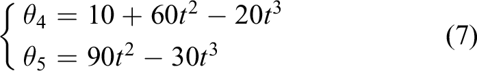
Based on the planning joint trajectory, we were able to obtain the corresponding motion curves of the hip and knee joints. Specifically, Figure 6 displays the joint motion angle, Figure 7 presents the joint motion angular velocity and Figure 8 shows the joint motion angular acceleration.
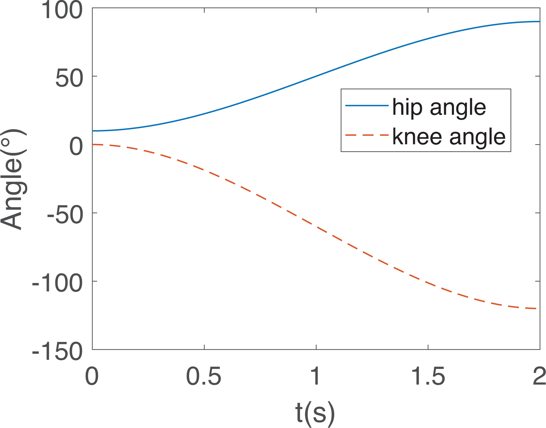
Hip and knee joint motion angle.

Angular velocity of hip and knee motion.

Angular acceleration of hip and knee motion.
In turn, the robot joint trajectory can be derived from the motion trajectory planning of the lower limb. The resulting values of the joint angles, angular velocities, and angular accelerations of the first and second joint of the robot are presented in Figures 9 to 11.

Robot joint movement angle.
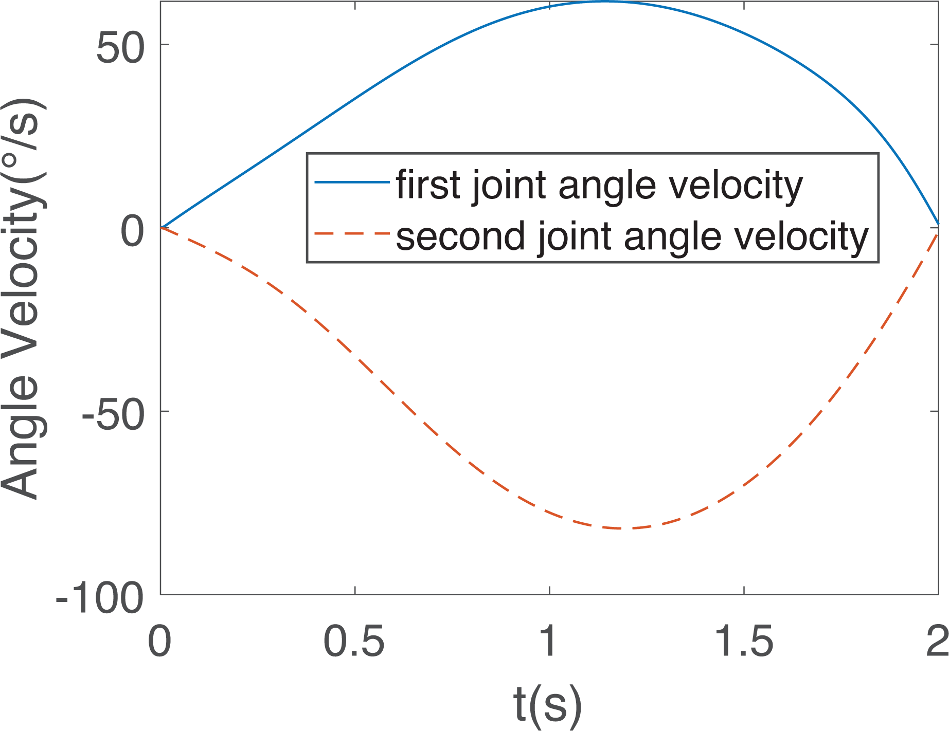
Angular velocity of robot joint motion.

Angular acceleration of robot joint motion.
Human–robot dynamics study
Dynamic modeling is a critical aspect of the design and control of rehabilitation robots. By the dynamics simulation calculation provides the theoretical basis for the lightweight design and servo control of the robot. The methods of dynamic modeling typically include the Newton–Euler method and the principle of virtual work. The former requires the establishment of the motion relationship of each joint, followed by the recursive extrapolation of the torque of each joint. However, this method is not commonly used in two-degree-of-freedom models due to the large number of solved equations required.
On the other hand, the principle of virtual work method offers a more intuitive approach to understanding the relationship between force and motion. This method considers the system’s energy perspective and establishes the differential equation of system energy to system variables using the Lagrangian formulation. The principle of virtual work method is easy to understand and is suitable for modeling the dynamics of two degree-of-freedom robot.
Human lower limb dynamic modeling
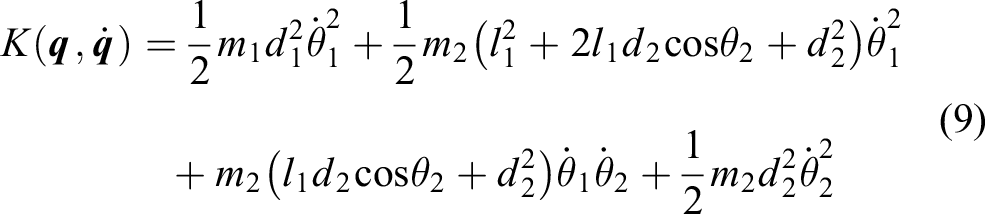
The human body model is considered as a two-link model in which the mass inertia parameters of the foot and lower leg are combined. From the Lagrangian formulation, we obtain

where
The kinetic energy of the system of the two-link model is
The system potential energy is

The joint torque of the two-link model is

where
Design of robot dynamic parameters based on dynamics simulation
The appropriate setting of robot joint dynamic parameters is crucial in the design and control of rehabilitation robots. In the context of the human–robot coupling relationship, the rehabilitation robot provides power for the movement of the human lower limb. To ensure proper and efficient operation of the robot, it is necessary to ensure that it can provide sufficient power.
In this article, a rehabilitation robot was developed to aid lower limb rehabilitation by utilizing a combination of servomotor and harmonic reducer to provide power to the robot. To determine the parameters of the servomotor rated torque and reducer reduction ratio, the maximum torque required for the first joint and the second joint of the robot was calculated through a dynamics model.
The generation of motion in the human body is intimately connected to the application of force. In this context, it is possible to infer the magnitude of force by observing motion. To understand the relationship between force and motion, we may consider the example of lower limb flexion and extension movements involving the hip and knee joints.
In this article, we referred to the inertial parameters of adult human body 20 to obtain important information about the mass and center of mass of each segment of the human lower limb. Specifically, Table 2 presents the ratio of the mass of each lower limb segment to the overall mass of human body, while Table 3 provides the relative position of the center of mass for length of each body segment.
Ratio of the mass of each body segment to the overall mass of the human.

Ratio of the relative position of the center of mass of each body segment to the length of each body segment.

For our study, we considered an adult male with a mass of 70 kg. Based on the information from Table 2, we were able to calculate that the mass of the thigh was 9.933 kg, the mass of the calf was 2.569 kg, and the mass of the foot was 1.036 kg.
To determine the relative position of the center of mass for each segment, we utilized the information presented in Table 3. Specifically, we found that the distance from the center of mass to the hip joint was 0.211 m when the thigh length was 0.465 m. Similarly, the center of mass to the knee joint of the calf was 0.156 m when the calf length was 0.396 m, while the distance from the center of mass to the ankle joint was 0.036 m for a foot length of 0.074 m. After merging the length of the lower leg and foot, we calculated the distance from the center of mass to the knee joint as being 0.235 m. The total mass was determined to be 3.605 kg.
We employed a cubic polynomial motion trajectory and the kinetic parameters of an adult man weighing 70 kg to calculate the torque values of the hip and knee joints during human movements. By comparing with the influence of body segment’s gravity, we generated Figures 12 and 13. As evident from both figures, the effect of gravity on the joint torque is significant. Therefore, when dealing with human–robot coupling dynamics, it suffices to take into account the total weight of the lower limbs that can be loaded at the robot’s end.

Hip joint torque.

Knee joint torque.
In the context of human–robot coupling analysis, it is established that the weight of the human lower limb predominantly loads onto the end of the second link of the robot. Thus, to calculate the torque of the first and second joints of the robot, we can regard the weight of the human lower limb as a load at the end of the second link. From the principles of robot statics, it is known that the gravitational force acting on the end can be translated into joint torque by means of the robot Jacobi matrix.
The robot dynamics model also uses the two-link model. Assuming that the weight of the first and second links in the model is 10 kg, and since the length of the links is 0.36 m, it is assumed that the distance from the center of mass of both links to the joint axis is 0.2 m. Furthermore, the end of the two-linked robot was loaded with a total weight of 13.538 kg of lower limb. By calculating the joint torque of the robot, we generated Figures 14 and 15. As depicted in both figures, gravity comprises a significant portion of the robot’s power, including both the robot’s own gravitational force and that of the end load.

Torque of the first joint of the robot.

Torque of the second joint of the robot.
Regarding the joint torque values, it is noteworthy that the first joint torque had a maximum value of 127.6 Nm and a minimum value of −57.67 Nm, while the second joint torque had a maximum value of 75.25 Nm and a minimum value of 39.87 Nm. These results provide important insights and can inform the design and optimization of related robotic systems.
To drive the first and second joints of the rehabilitation robot, we have opted for 200 W medium inertia servomotors with a rated torque of 0.64 Nm. It was necessary to use a harmonic reducer with a reduction ratio of 200 for the first joint to achieve a rated load torque of 128 Nm. This choice helps ensure that the maximum torque of the first joint remains within the rated torque of the servomotor. Similarly, for the second joint, a harmonic reducer with a reduction ratio of 160 was used to achieve a rated torque of 102.4 Nm, which is greater than the maximum torque of 75.55 Nm predicted by the simulation.
The third and fourth joints, which are less affected by the gravity of the human lower limbs due to the placement of the lower leg support mechanism at the third joint, were selected to be driven by 100 W medium inertia servomotors with a rated torque of 0.32 Nm each. As a result, harmonic reducers with a reduction ratio of 100 were used for both joints, resulting in a joint load torque of 32 Nm. These motors and reducers provide sufficient power to drive the ankle in plantarflexion and dorsiflexion, as well as adduction and abduction.
Experiment under the action of human–robot coupling
The proposed lower limb rehabilitation robot is designed to be positioned beside a hospital bed for use, as presented in Figure 16. The patient is lying in bed, and initially, the robot needs to extend its robotic arm. The physiotherapist then places the lower limb that need rehabilitation on the robot. Subsequently, passive rehabilitation training and lower limb size parameters are set according to the specific requirements of joint rehabilitation. The robot is capable of executing various lower limb rehabilitation training, such as bicycling, as well as common supine position movement patterns for humans, like straight leg lift. Moreover, since the leg support mechanism on the robot reduces the weight of the lower extremity, there is less power requirement on the motion of the robot’s rear two joints. As such, it is no longer verified whether the latter two joints can provide sufficient power.

Working diagram of the lower limb rehabilitation robot.
The experiment involved using the robot to perform passive rehabilitation training on a healthy male subject, standing approximately 1.75 m tall and weighing around 73 kg. During training, the subject’s lower limbs remained completely relaxed. The robot controller generated joint trajectories obtained from inverse kinematics, which were subsequently sent to the driver for execution. The driver used pulse commands to operate the servomotor, while an encoder attached to the motor provided real-time feedback on its angle of rotation. The current of the servomotor was monitored in real time by the driver and converted into a voltage signal to represent motor output torque. This voltage signal was collected via a data acquisition card and transformed into joint torque values based on the joint reducer ratio.
The rehabilitation robot utilized industry-standard servomotors and drivers. The driver is configured to operate in position mode, so the results demonstrate that the actual motion trajectory of the robot closely aligns with the planned trajectory, as depicted in Figure 17. It represents the trajectory of the end of the robot’s second link in the robot coordinate frame. It should be noted, however, that the human body is flexible and not tightly coupled with the robot, and lower limb joint movement angles have a degree of error. The lower limb joint angles were measured using a goniometer, and while the measurement accuracy was not found to be high, the joint angles were observed to be close to the planned angles (Figure 18). The range of motion of the hip joints during the experiments was found to be between 11° and 87°, while the range of motion of the knee joints was between 0° and −113°. These observations indicate that the robot system is capable of effectively achieving lower limb rehabilitation motion.

Actual and desired trajectory of the second link end of the robot in the base coordinate frame.

Measurement of actual motion angles of lower limb hip and knee joints.
The results of robot joint torque are presented in Figures 19 and 20, where the maximum torque value for the first joint was found to be 136.7 Nm, with a minimum value of 27.7 Nm. Similarly, the maximum torque value for the second joint was found to be 34.14 Nm, with a minimum value of −29.08 Nm.
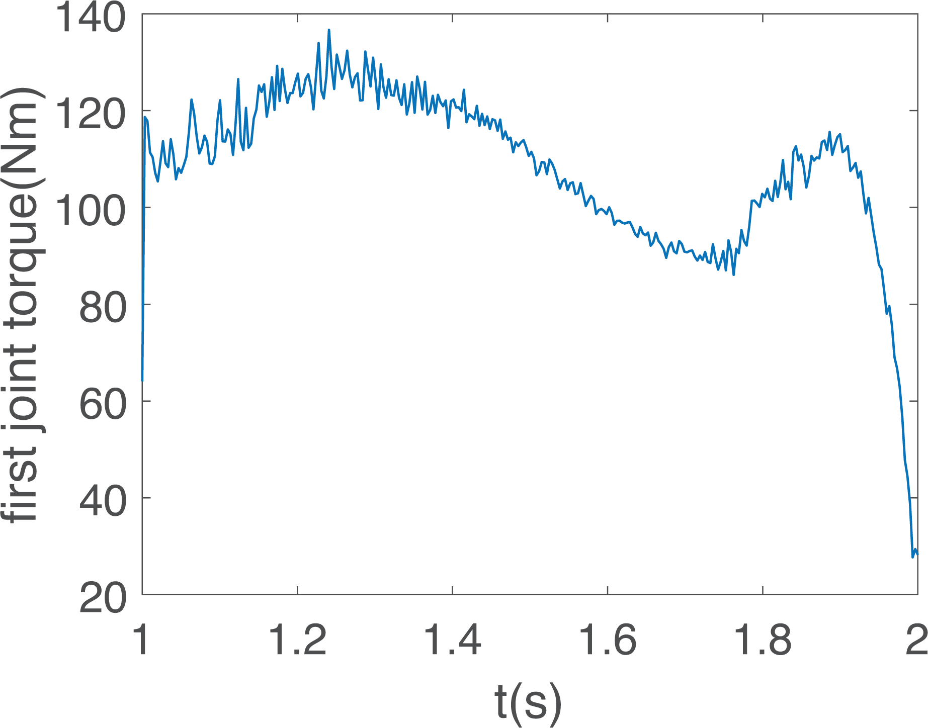
Actual working torque of the first joint of the robot.

Actual working torque of the second joint of the robot.
The simulated maximum working torque value of the first joint of the robot was found to be lower than the actual measured value due to the absence of friction in the simulation. Friction, which is typically modeled as Coulomb friction and viscous friction, has a significant influence on the joint torque of the robot. The experimental results showed that the presence of friction in the robot’s joints had a considerable impact on the overall performance. The higher value of joint torque observed during the experiments can be attributed to two main factors. Firstly, the robot design utilized a belt drive system. Since the belt is driven by friction and is inherently flexible, power losses occur due to deformation. Moreover, the friction force is further increased, and the power loss is augmented due to the installation error of the belt pulley and the varying degrees of tension.
Secondly, the choice of harmonic reducer with a large reduction ratio can also affect the robot’s performance. The efficiency of the harmonic reducer decreases as the reduction ratio increases. Moreover, the overall system reduction ratio becomes too large, which results in an increase in the rotational inertia ratio of the system, causing the robot to have a high starting torque.
Despite these challenges, it is noteworthy that the robot designed in this study does not require continuous high torque output. Furthermore, the peak torque of the servomotor is typically more than three times the rated torque. Therefore, although the system is subject to high starting torque due to the large reduction ratio of the harmonic reducer, the designed robot is capable of performing normally, and the peak torque of the servomotor can satisfy the requirements of the robot’s operation.
Conclusion
In this article, a passive compliant lower limb rehabilitation robot was designed to facilitate the lower limb rehabilitation training of patients in a supine position. The robot allows for the flexion and extension movements of the hip, knee, and ankle joints, as well as the adduction and abduction movements of the ankle. In addition, the incorporation of two degrees of freedom in the ankle joint enables the robot to function as a wearable ankle rehabilitation training device, thus promoting comprehensive lower extremity rehabilitation training.
The structural parameters of the robot model were designed based on the establishment of a human–robot kinematic model and an analysis of human–robot coupling characteristics. The dynamic simulation of the robot model was performed based on the human lower limb inertia parameters and the target inertia parameters of the robot. This allowed for the completion of the design of the robot power system.
To ensure that passive rehabilitation training is safe and comfortable, a coupled transformation process from human lower limb motion trajectory planning to robot trajectory planning was designed. This process ensures that the passive rehabilitation training trajectory aligns more closely with the lower limb motion law, while further reducing the impact of the robot on the lower limb through the use of a passive compliant mechanism. Through this approach, the safety of the rehabilitation process can be enhanced. In the future, we wish to apply dynamics modeling to robot control and achieve active rehabilitation.
Footnotes
Declaration of conflicting interests
The authors declared no potential conflicts of interest with respect to the research, authorship, and/or publication of this article.
Funding
The authors disclosed receipt of the following financial support for the research, authorship, and/or publication of this article: This work was supported by the Project of science and technology of Henan Province (212102310890) and (212102310249).