
Abstract
Landmine detection capability of metal detectors is very sensitive to the gap between buried landmines and the sensor heads. Therefore, human deminers manually scan ground surface with the metal detectors in such a manner that the sensor heads follow the ground surface. In case of robots assisted landmine detection, this function can be performed accurately and safely by controlling the gap and attitude of the sensor heads. In this investigation, the effectiveness of the gap and attitude control of the sensor head by some mechanical manipulator on the landmine detection performance has been addressed quantitatively. To this end, the paper describes the development of a Controlled Metal Detector (CMD) for controlling the gap and attitude of the sensor head. The CMD generates trajectories of the sensor head from the depth information of the ground surface acquired with 3-D stereovision camera in order to avoid any obstacles and possible impact with the ground, and then tracks the trajectories with a trajectory-tracking controller. The effectiveness and the impact related to the gap and attitude control on the landmine detection performance of the CMD have been demonstrated by experimental studies.
Keywords
Introduction
Millions of landmines are still buried under the ground surface all over the world causing threats to the lives and economy of mine-affected nations. Humanitarian landmine detection and removal has become a serious global issue. In order to make this mission successful, landmine detection and removal rate should be nearly 100%. The manual landmine detection and removal is still carried out for reasons of the reliability, however it is very slow method. In addition, the detection rate is very poor and at the same time, it is very dangerous for the life of the operating personnel. Our research team has developed a robot assisted mine detection method that is safe, more accurate and faster than manual method (Nonami, K. et al. 2003).
Metal detectors are considered as the most reliable sensors for mine detection work. However, landmine detection performance of the metal detectors is highly dependent on the distance between the sensor heads and the buried landmines. Therefore, the landmine detection performance of the metal detectors could be substantially improved if the gap and attitude of the sensor heads can be controlled. In case of robots assisted land mine detection, this function can be performed in a convenient manner where the sensor heads should accurately follow the ground surface maintaining almost uniform gap between the ground surface and the sensor heads by controlling the gap and attitude of the sensor heads.
Few mine detection robots that have the capability to recognize ground surface and can control the gap and attitude of the sensor heads are reported in (Armada, M.A. et al. 2005), (Chesney, R. et al. 2002), (Nonami, K. et al. 2003).
However, to the best of the knowledge of the authors, no research work has been reported in the literature that quantitatively addressed the relationship between the landmine detection performance and controlling the gap and attitude of the sensor head to the ground surface.
In view of the above, authors' research group has developed a Controlled Metal Detector (CMD) having 3-DOF for any arbitrary positioning of the sensor head. The CMD system can generate 3-D high-speed mapping of the ground surface and can generate trajectories of the sensor head with 3-D stereovision camera. 3-D stereo vision is now being widely used for 3-D mapping and robotics (Clark, F. et al. 2007), (Rochaa, R. et al. 2005), (Xiao, D., et al. 2004) for their powerful sensing capability than other range sensors.
The CMD system adopts 3-D stereovision camera rather than LASER scanning as a range sensor because 3-D stereovision camera can capture color information also. Ground of real minefield may have substantial amount of vegetation. Therefore, some image-processing algorithm could be applied with the color images captured by the CCD cameras for recognition of the vegetation to autonomous operation of the CMD in vegetated minefield in future work.
The trajectories are generated by the CMD in such a manner that any obstacle or possible impact with the ground can be avoided. The CMD then tracks the generated trajectories by a trajectory-tracking controller so that the sensor head can follow the ground surface. The effectiveness and the impact related to the gap and attitude control on the mine detection performance of the CMD have been demonstrated by experimental studies.
The rest of the paper is organized as follows. The description of the controlled object has been presented in section 2. The kinematic analysis of the CMD has been presented in section 3. The description of stereovision camera has been presented in section 4. The description of trajectory planning has been presented in section 5. The results of experiments of trajectory tracking have been presented in section 6. The results of experiments of mine detection have been presented in section 7, 8. The conclusions have been presented in section 9.
Controlled Object
The controlled object of this research is called Controlled Metal Detector (CMD). It consists of the two-coil metal detector and a 3-DOF mechanical manipulation mechanism driven by electric motors. The overview of the CMD system is shown in Fig. 1. The experimental setup is composed of the main body of the CMD, two PCs, 3-D stereovision camera and a XY-stage as shown in Fig. 2. The XY-stage can perform the two-dimensional motion in horizontal directions.

Overview of CMD system

Architecture of CMD system
The schematic diagram of the CMD is shown in Fig. 3. The CMD has 3-DOF composed of three motorized linkages (Link 1, Link 2, and Link 3). The ball screws on these links convert the rotational motion into translation motion. The gyrations of pitch and roll, and movement in vertical direction of the sensor head are performed by controlling the lengths of the Link 1, Link 2 and Link 3. The right-handed coordinate system {Ob Xb Yb Zb} associated with the CMD is described in Fig. 3. The lengths l1, l2 and l3 (of Link 1, Link 2 and Link 3 respectively) are measured with encoders installed in each link. The calculation methods are described in next section.

Configuration of CMD
The CMD is mounted on the horizontal positioning arm of the XY-stage at the point Pa. Therefore, the point Pa does not move vertically. After the synchronization of the CMD and the horizontal positioning arm of the XY-stage, it is possible to make the sensor head to follow the target trajectories generated with 3-D stereovision data. Moreover, the CMD has no metallic parts within 600 mm from the sensor head; this practically eliminates any chance of interference on the metal detector. Table 1 shows the specifications of the CMD.
Specifications of CMD

The movements of Link 1 and Link 2 are restrained in the perpendicular plane because there is a ditch on the ball joint Pb. The geometrical relationship between the lengths l1, l2 and the pitch angle θx, roll angle θy of the sensor head shown in Fig. 4. In the CMD system, in order to ensure that the sensor head follows the ground surface without any collision, the trajectory of the attitude of the sensor head and the required change in l3 are calculated with 3-D vision data. Then the changes in lengths l1, l2 are calculated from the inverse kinematics as shown below (1) and (2).

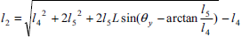
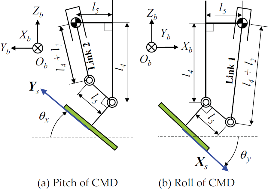
Geometry of CMD
Moreover, the direct kinematics is as follows.


Where l4 and l5 are lengths of links, and
The commercial stereovision camera, called Bumblebee (Point Grey Research Inc.), has been used for 3-D stereovision based ground mapping. This stereovision camera uses a parallel stereo method. Table 2 shows the specifications of the stereovision camera. Where the coordinate system consists of: the original point and the Zc axis are taken the optical center and the optical axis of the left camera, the Xc axis and the Yc axis are taken the horizontal axis and the vertical axis of the left image, is defined as the camera coordinate system {Oc}.
Specifications of stereovision camera
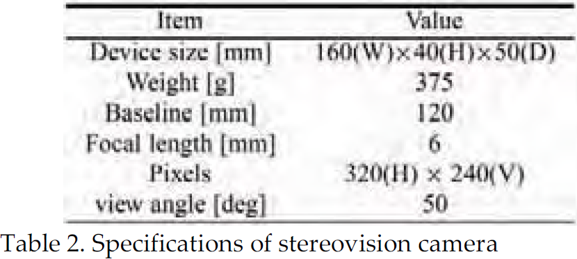
Specifications of stereovision camera
The stereovision algorithm searches for correspondence points between the left image and the right image acquired with the stereovision camera by the template match. The camera coordinate [xc, yc, zc]T of point P in the 3-D space is decided from correspondence points p, p′ in the right and left images as follows.

Where the positions of correspondence points p and p′ on the right and left images are defined as (xl, yl), (xr, yr).
As a result, geographical features information in the camera coordinate system is acquired. Therefore, depth information fa(x, y) on the ground surface in the base coordinate system is generated with the coordinate conversion. Here a photograph of the detection area as an example is shown in Fig. 5, and the 3-D geographical features map is shown in Fig. 6.

Detection area

3-D mapping
The trajectory planning is produced by the off-line. Namely, at first, the 3-dimensional map for the detection area like 1m × lm will be produced by means of the stereovision based image processing, and then, the trajectory planning will be automatically done.
The target trajectory has been generated from the depth information acquired with 3-D stereovision. However, the raw depth information from the stereovision camera contains large data volume and also noise. This large volume of data is inconvenient for the trajectory planning. Therefore, a working depth information f(n1, n1) has been generated from the original depth information fa(x, y) provided by the stereovision camera after sampling it at a grid interval dg. Thus, the working depth information f(n1, n2) can be written as:

Where n1 and n2 are assumed integers.
This working depth information f(n1, n2) on the grid has been used in the trajectory planning algorithm.
Fig. 7 shows the trajectory of the mounting point Pa of the CMD on landmine detection area (lx × ly). The point Pa moves parallel to the Xb - Yb axis with velocities vx and vy respectively. Here, it is necessary to change the velocities of the point Pa depending on the ground surface. However, during the experiment the velocities vx and vy are kept equal because of the technical limitations of the XY-stage.

Trajectory of XY-stage
During the trajectory planning, first the position and attitude angles of the sensor head are decided on each grid point of f(n1, n2); then these discrete points in the space are connected by straight lines to generate a continuous trajectory. The following objectives are to be satisfied during the trajectory planning:
The sensor head keeps itself approximately parallel to the ground surface. The collision between the sensor head and the ground surface is avoided.
The target attitude angles θx and θy of the sensor head that fulfill the first objective stated earlier can be obtained from the depth information as the inclinations of the ground surface. The Xb axial inclination at the grid point (n1, n2) of the ground surface is decided by the least square method as follows.
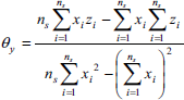

θx is similarly decided. Where ks is defined as an inclination coefficient of determination. However, the target attitude angles are decided in restrictions. One of the restrictions are is the movable ranges of the mechanism. Another one is the limits of attitude movements θdx and θdy between each grid point that consider the passing velocity, vx and vy, of the point Pa. The limits of the attitude movements θdx and θdy are shown below. Where ωMAX shows the maximum angular velocity.

Length l3 of Link 3 that fulfills the second objective stated earlier is decided with the attitude angles. When the position of the point Pa is Pa = [n1dg, n2dg, Paz]
T
, the position of the center point of the ball joint Pb is Pb = Pb = [n1dg, n2dg, Paz – dz – l3]
T
. Where the fixed height of the point Pa is assumed to be Paz. Moreover, the distance between the point Pa and the point Pb in the basic stance is assumed to be dz. Where position S at the center point S on the sensor head's bottom is as follows with attitude vectors Xs and Ys on each grid point.
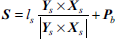
Where ls is defined as the distance between the point Pb and the point S. At this time, all the points on the sensor head's bottom keep a distance more than a safety allowance lmar to the ground surface. Therefore maximum length l3 is decided as filled above. However, l3 is decided in the restriction of the movable range of the mechanism.
Because this trajectory planning targets at minefield, the length l3 of Link 3 is decided again so that the sensor head does not touch the ground surface in spite of the delay is caused in each response of the Links.
On the ith grid point of the trajectory that XY-stage passes, the position of the point Pa is assumed to be Pa(i) = Pa = [n1(i)dg, n2(i)dg, Paz]T, the pitch angle and the roll angle of the sensor head are assumed to be θx(i), θy(i) and the length of Link 3 is assumed to be l3(i).
In the present research, the CMD does the following three operations at the same time.
Attitude changes of the sensor head Vertical motions of the sensor head Xb and Yb axial motions by XY-stage
Here the length l3(i) of Link 3 is decided again so that the CMD safely accommodate the time delay caused by these three operations. Here, these three operations are assumed to be completed by the arrival time dg/vx, dg/vy to the next grid point.
The length l3(i) is decided again so that all the points on the sensor head's bottom may keep the gap to the depth information on the grid point more than the safety allowance lmar as shown in Fig. 8, evenif the points Pa is at Pa(i−1) and Pa(i+1) with the target attitude angles of the sensor head of the m grid point. Thus, the collisions with the ground surface caused by the delay of the response can be avoided. However, l3(i) is decided in the restriction of the movable range of the mechanism and the limits of the expansions ldx and ldy between each grid point that consider the passing velocity, vx and vy, of the point Pa. The limits of the expansions ldx and ldy are shown below. Where vMAX is assumed the maximum expansion velocity of Link 3.


Decision of l3
Fig. 9 shows an example of the generated target trajectory at the center of the sensor head's bottom.

Trajectory generation
The trajectory following experiments of the CMD are conducted over the detection area (600 mm × 40 mm) shown in Fig. 10. 3-D range information of the detection area is acquired with the stereovision camera in the experiment and the target trajectory is generated using the methods stated earlier. Here each control input to the motor drivers of the CMD is generated with PID controller of feedback control system so that each expansion of the Links follows to the target trajectory. Where the sampling frequency is taken as 50 Hz. Moreover, each gain of the PID controller is shown in Table 3, and each parameter in the trajectory planning is shown in Table 4.

Detection area for experiment
Gain of PID controller

Parameters of trajectory generation

Fig. 11 showed the generated target trajectory and the result at the center of the sensor head's bottom in the experiment. Fig. 12 showed the time change of the vertical minimal gap between the sensor head's bottom and the ground surface. Fig. 12 shows not real data, but the final data after signal processing in the PC. In addition, these spike peaks are caused by the discrete data like Fig. 8. Moreover, the target trajectory and the response of each expansion of Link 1, Link 2 and Link 3 from the experiment beginning for four seconds are shown in Fig. 13.

Trajectory of sensor head

Gap between sensor head and ground surface

Trajectory responses of links
From Fig. 11, it is obvious that the sensor head follows the generated target trajectory very well. In addition, the sensor head almost keeps the gap more than the safety allowance lmar (Fig. 12) during the detection work, and the trajectory that fulfills the target specifications without contact with the ground surface has been achieved. The safety allowance defined 3.S lmar = 10 mm was appropriate in this experiments. Moreover, each link has an excellent trajectory following performance with a small overshoot and delay respectively as shown in Fig. 13.
Methods of Estimating the Position of Buried Landmines
Estimating the position of the buried landmines with the data of landmine detection sensors is important in detection work by mine detection robots. The metal detector used in this research has a property that the frequency of the output changes before and after the metal detector mounted on the CMD is passing over a buried metallic object. By using this property, the output signal from the metal detector is converted to a negative value when a landmine exists on the right side from the center of the sensor head along the Xb axis, and to a positive value when a landmine exists on the left side from the center of the sensor head along the Xb axis. The position of the buried landmine is estimated with the processed output of the metal detector. This section shows the method of estimating the buried position that is confined to the case of the detection area with only one buried landmine.
The sensor head is scanned Xb axially in N times in each landmine detection experiment in this research as shown in Fig. 7. In each Xb axially scanning, the strength of the metal reaction: mi and candidate position of the buried landmine: [xi, yi] are decided with the output of the metal detector. After all (N times) scanning finished, the estimated position of the buried landmine is decided with each strength of the metal reaction and each candidate position of the buried landmine as follows.

Where in the ith scanning, the candidate position of the buried landmine [xi, yi] is decided as the middle point of the positions in which the metal reactions pass the threshold Vd[V] or -Vd[V] along the Xb axially with keeping the output increases. In addition, the strength of the metal reaction mi is assumed a difference between the maximum and minimum values in neighborhood at the candidate position as shown in Fig. 14. Where it is assumed that Vd = 0.2 V and N = ly/yd + 1 in this research.

Definitions of the candidate position (ith scanning)
Various roughnesses are given to detection area (lx × ly) of sands shown in Fig. 10, and the landmine detection experiments by the CMD are conducted. The position of the buried landmine is estimated with acquired data of the metal detector, and effectiveness of the gap and attitude control of the sensor head to landmine detection performance is verified. Here the control method is assumed same to the experiments of trajectory tracking in section 6.
Experimental Conditions
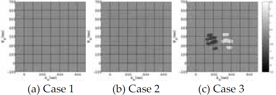
Three kinds of trajectories are defined in this experiment to verify effectiveness of the gap and attitude control to landmine detection performance and they are compared. Where Case 1 is a target trajectory that fixes the sensor's posture horizontally with keeping the safety allowance lmar to the highest point of the detection area. Case 2 is a target trajectory that fixes the sensor's posture horizontally, and controls only the gap between the sensor head and the ground surface. Case 3 is a proposed target trajectory that controls the gap and attitude of the sensor head to the ground surface.
The buried landmines are the mostly antipersonnel landmines all over the world, PMN2 (φ 125 mm × 54 mm), made of plastic in Fig. 15 (a) and have some metallic parts. Depths of the buried landmines are defined as the distance between the ground surface and the upper surface of the landmines as shown in Fig. 15 (b). In addition, the buried position was assumed to be [x, y] = [300 mm, 300 mm] on base coordinate system.

Target mine
About conditions concerning the ground surface, a smooth ground surface is defined as area A, the ground surface, where the position of the buried landmine is slopes, is defined as area B and the ground surface, where it is the valley part of two mountains, is defined as area C. Moreover, roughness of the ground surface is assumed to be shown in based on the roughness of the extent that the sensor head can accurately follow. The depth information f(n1, n2) on the grid is assumed an original curved surface. Moreover the curved surface obtained from the original curved surface with the lowpass filter, the cutoff wave length 40 dg [mm], is defined as the average curved surface W(n1, n2). Therefore, the root-mean-square roughness Rs in the ground surface is defined as follows.
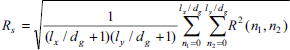
Where lx/dg, ly/dg are made to become to the integer and rough curved surface R(n1, n2) is defined as follows.

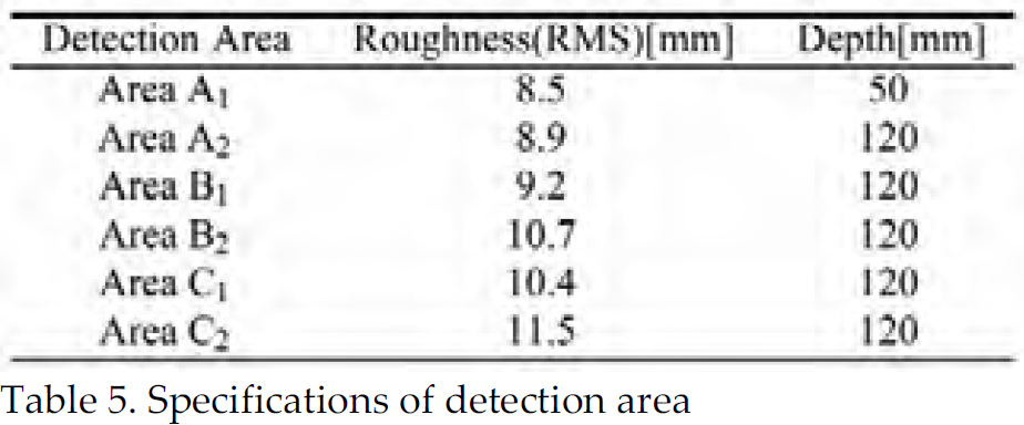
In this experiment, the range of the detection area is assumed to be lx = 600 mm and ly = 600 mm, and each parameter is assumed to be same shown in Table 4. Table 5 shows the root-mean-square roughness Rs and the depth of the buried landmine in this experiment.
Specifications of detection area
The results of the landmine detection experiments in each detection area were shown in Fig. 16–21. In these figures, the processed outputs of the metal detector were plotted at the trajectory of the center of the sensor head's bottom. The larger absolute values of the outputs showed that the distances between the sensor head and the buried landmines were shorter.

Area A1

Area A2

Area B1
Area B2

Area C1

Area C2
Moreover, the estimated positions of the buried landmines in each detection area by the method of the description in section 7, were shown in Table 6. In addition, in Table 7, these values were the integrated absolute values of the outputs of the metal detectors at the detection time to show the effectiveness of the gap and attitude control. Where relative values were indicated, in which the values of Case 3 were assumed 100.
Estimated position of landmine

Numerical integration value of metal detector

In the detection areas except Area A1 where the depth of buried landmine is shallow, the metal reactions of Case 1 without the gap and attitude control are small, so the landmine detection performance is obviously inferior. It is clear that the gap control of the sensor head is necessary and indispensable in mine detection robots.
In the following, Case 2 and Case 3 are considered. The attitude change in Case 3 is small in a smooth ground surface, so the difference in the detection performance according to two methods, is small as shown in Fig. 16, Fig. 17 and Table 7. The buried position of both Case 2 and Case 3 can be estimated with good accuracy.
If the roughness of the slope is small, the result of Case 3 resembles a metal reaction in a smooth ground surface as shown in Fig. 18. Because the sensor head becomes parallel on the slope in Case 3.
When the ground surface is rough as shown in Fig. 19–21, the metal reaction is lost in Case 2 that is not able to change the attitude. While the metal reaction is clear in Case 3. It is shown to be able to estimate the position of the buried landmine.
As for this result, effectiveness of the gap and attitude control to the landmine detection performance is clearly shown also in Table 7. However, the error is greatly caused in the estimated position of the buried landmine according to the result of Area C2. Because the gap is greatly caused at the center of the sensor head's bottom, when the attitude angle grows. It is a disadvantage in the attitude control.
Conclusions
In the present investigation the development of a Controlled Metal Detector (CMD) for controlling the gap and attitude of the sensor head has been presented. The trajectory planning of the sensor head with 3-D stereovision has been carried out for controlling the gap and attitude of the sensor head to the ground surface. The safety margins considered during the development of the trajectory planning algorithm makes it robust against any accidental collision of the sensor head when it is intended to scan an uneven mine affected area. The trajectory planning algorithm makes all efforts to control the gap and attitude of the sensor head such that it follows the uneven ground surface that is conducive for the mine detection by the metal detector. The experimental results presented in this paper exhibit the effectiveness of the CMD for buried landmine detection over uneven ground.
Footnotes
10. Acknowledgements
The authors would like to thank Japan Science and Technology Agency for sponsoring this research.