
Abstract
Equipping autonomous robots with vision sensors provides a multitude of advantages by simultaneously bringing up difficulties with regard to different illumination conditions. Furthermore, especially with service robots, the objects to be handled must somehow be learned for a later manipulation. In this paper we summarise work on combining two different vision sensors, namely a laser range scanner and a monocular colour camera, for shape-capturing, detecting and tracking of objects in cluttered scenes without the need of intermediate user interaction. The use of different sensor types provides the advantage of separating the shape and the appearance of the object and therefore overcome the problem with changing illumination conditions. We describe the framework and its components of visual shape-capturing, fast 3D object detection and robust tracking as well as examples that show the feasibility of this approach.
Introduction
Robots, whose niche is located in home or office environments, are in need of sensors providing robust information about its current position as well as the objects it can handle. Vision is the richest of human senses and therefore predestined to be used in robots as well. Our long-term goal is a robot that is capable of doing well in a scenario like this: The object of interest is shown to the robot once, e.g. my favourite coffee mug that is currently with me in the kitchen. Later on, say, sitting in front of the TV-set, I tell my robo-friend « Please, bring me my cup! ». Now, it should be able to search potential object places like kitchen boards and, of course, my computer desk where I left it, in order to detect the cup it was shown before. Tracking is needed for the subsequent visual servoing during the grasping task. Bringing me the cup will therefore only afford a single task by me: Just telling the robot what I want. This, of course, implies the need for a suitable object representation in the robot. A lot of techniques regarding object detection, tracking and learning for acquiring the necessary data about objects have been published in the last decades. However, the bottom line is that usually human interaction between the single phases is needed when these techniques are integrated in a physical robotic system. Often, the object descriptions are retrieved by expensive off-line learning such as providing a huge database of views for the training images or – in a simplified manner – by hand-coding the wire-frame model of the object.
Furthermore, the significant drawback encountered when working with cameras is their dependence on the lighting conditions. The representation of objects in terms of their visual appearance assumes similar lighting conditions in the later processing. Restrictions to controlled environments are often the consequence. For a more detailed review of related approaches please refer to Sec. 1.1.
To put it in a nutshell, robotic research has increasing demand for vision sensors providing different functionalities (representation of objects, detection and tracking) working seamlessly without user interaction in a robust manner. In Sec. 2, we will introduce the concept of our vision system in detail and the two main techniques used, Superquadrics and interest point tracking. The Concept is devised to overcome the problem of appearance differences during a first shape-capturing phase and the subsequent detecting and tracking phases. It is also developed to avoid user interaction between the phases for achieving an automated system applicable in robotics. We will show that one simple fact helps exploiting the advantages of both shape- and appearance-based descriptions to be used as internal representation of objects in the robot: Everyday objects that are prone to be handled by service robots tend to consist of primitive convex geometrical shape, especially rectangular boxes and cylinders and can therefore be described by a Superquadric model which is shortly explained in Sec. 2.1. Such a description is purely shape-based and therefore not influenced by illumination conditions when being retrieved, but the richness of the appearance information of the object can nevertheless be exploited when coming to the detection and tracking phase – in our case in form of interest points described in Sec. 2.2. Sec. 3 gives a first implementation of this concept and describes how the Superquadrics and the interest point tracking technique are combined to automatise the procedure of the three phases of shape-capture, detection and tracking. To enable the integration of these phases the calibration of the sensors used is necessary and outlined in Sec. 3.4. Finally, Sec. 4 shows experiments performed with our setup and different everyday objects.
Related Work
In (Kragic, D. & Christensen, H.I., 2002), the importance of combining shape and appearance is stated for robotic servoing and grasping tasks, because the robustness of model based techniques for tracking line features of highly textured objects is lacking. Their solution to overcome these problems lies in the usage of training images with subsequent projection into eigenspace, which only slightly reduces the sensitivity to illumination conditions in open environments.
Information about the objects of interest for the different tasks is currently often provided off-line by manually storing them in a database. For example, (Han-Young, J. et al., 2005) use complete solid model representations in an object database for all objects that can be manipulated. The SIFT features that describe the objects and graspability or accessibility information are stored therein as well. In (Sungho, K. et al, 2003), off-line computed Zernike moments around interest points are stored in a database for later being matched via a probabilistic voting during the on-line process. Additionally, recognition is verified by aligning model features to the input scene.
Concerning learning, pioneer work for 3D object recognition has been done by (Mukherjee, S. & Nayar, S.K., 1995); (Salganicoff, M. et al., 1996) provided an approach for active learning for robot grasping in a vision-based fashion.
(Krivic, J. & Solina, F., 2004) perform object recognition with Superquadrics by using a recover-and-select paradigm, which affords a previous segmentation of the scene. The consistency of the match is checked using a set of constraints to determine part similarities. Regarding tracking, a lot of different methods have been introduced, similar to the system at hand is the work of (Krivic, J. & Solina, F., 2003) who also do monocular Superquadric tracking. Their approach is to extract edges in the image, then fit the projection of the Superquadric model onto the image and minimise a cost function. A recent paper by (Youngrock, Y. et al, 2005) shows a combination of a laser scanner and a camera for tracking complex objects (e.g. a toy lorry). However, the selection of line features needs to be done manually from the range image.
A system similar to the setup proposed here has been presented by (Taylor, G. & Kleeman, L., 2004) and consists of a laser range scanner and stereo cameras. Detection of geometrically primitive objects (boxes, bowls, cylinders) is performed without previous learning and requires a previous scene segmentation using surface curvatures.
Problem Description and proposed solution
The system proposed aims to solve a twofold problem. First, databases with the descriptions of known objects shall be avoided as this impacts the flexibility of the robot. Additionally, previous off-line learning is often time-consuming. And second, shape and appearance representations of the object shall be combined, as this would enable the difficulties with each of them to be minimised. Being more concrete, shape information discards a very rich channel of object descriptions, namely all surface texture information that everyday objects tend to contain. Appearance information, on the other hand, poses the problem of dependence on the illumination conditions.
We found that the combination of these two different vision functionalities can be nicely achieved by combining two different types of vision sensors, a laser range scanner (for the shape) and a colour camera (for the appearance). As object description, Superquadrics are used that describe the object to be handled in a straight forward and compact manner. This object information is generated when needed, without being predefined in a database. The rich appearance information is then exploited on the Superquadric just when it is needed – in the concrete tracking situation in the scene. This bypasses the problem with different illumination conditions during shape-capturing and tracking. In the following, this concept is described in a more detailed manner.
Design of the system
Fig. 1 shows the overall conceptual design of the system. In the first phase, the object of interest is shown unoccluded to the system. The laser scanner derives the necessary parameters for the later re-detection and tracking phase. As this phase captures size and shape rather than appearance information, we refer to it also as the shape-capturing phase. Note, that this shape-capturing is a special form of learning and different to usual visual learning techniques (see Sec. 3.1).

Conceptual Design of the system: Capturing the shape and size parameters (phase 1) of the object as well as detection in the scene (phase 2) is done by the laser scanner; the colour camera is liable for the tracking part (phase 3)
The second phase, the detection phase, takes place in an everyday cluttered scene where the object is re-detected by the laser scanner using the parameters derived before. Sec. 3.2 describes this phase in detail.
With the information from these two phases, the third and last task can be performed: in the tracking phase the object in the scene is followed for a grasping approach or other purpose (e.g. for visual servoing) – see Sec. 3.3.
The rationale for using a simple shape-capturing phase lies in the avoidance of databases of predefined objects.
The retrieval of the object geometries takes place when needed. Superquadrics, described in Sec. 2.1, are a good means for such a description as they are compact (using a sparse parameter description) and provide the possibility to describe a large number of different shapes. Everyday objects have the tendency to consist of basic geometric shapes, which can be described very well by this model.
As said, the usage of a laser scanner and a colour camera allows the separation of shape and appearance information. A laser scanner provides a three-dimensional point cloud of the (visible) surface of the object, independent of its appearance information. With other words, scanning the object in different illumination conditions delivers very similar results. This is why we use a laser scanner for shape-capturing and detecting the object. Showing the object to the robot in the kitchen (under, say, neon lamps) thus allows a redetection of the same object in the garden without getting confused by the different appearance of the object due to different illumination conditions.
However, shape information is - especially for tracking – not always the best choice. Often, edges are used, but with highly textured objects the amount of spurious edges can get high, making tracking almost impossible, see for example (Kragic, D. & Christensen, H.I., 2002) and (Vincze, M. et al., 2005). In such a case, appearance information that exploits textured surfaces is much better suited. Therefore, the tracker is initialised by the position and orientation delivered by the detection phase, but uses this information not to detect the edges but uses the shape information to search the surface for retrieving interest points. These points are tracked and the model is fitted using a projection of these points to the shape model. The output of the tracker is the current pose of the object of interest throughout the input frames. Interest points will be outlined in Sec. 2.2 and the particular implementation of the tracker used for our experiments in Sec. 3.3.
The system proposed needs a single parametric description that can easily be passed along the different phases. Multiple parametric models have been introduced to 3D computer vision with Superquadrics being very popular because of their small set of parameters but providing a large variety of different basic shapes at the same time. Recovery of Superquadrics is a well-studied problem and global deformations can be easily adopted, too (Solina, F. & Bajcsy, R., 1990). It may seem unwise to use a model description that is bound to basic and symmetric shapes. Our experience showed, however, that objects involved in manipulation tasks in home robot scenarios consist to the largest extent of such shapes. Examples are commodity items of typical box shape or cups, which are predominantly cylinders except for the handle, which could either be ignored or modelled by a second Superquadric. Another advantage of using this type of model description lies in its delivery of a closed surface. This is exploited by the appearance-based tracker like the one used in this system when computing the 3D coordinates of an interest point by intersecting the line of sight with the model. Sec. 3.3 will further elaborate on this.
Superquadrics are a family of parametric shapes, which have been first introduced in computer graphics by (Barr, A.H., 1981). They can be classified into Superellipsoid, Supertoroid and Superhyperboloid with one and two parts. In this work we focus on Superellipsoids that are proper for a volumetric part-based object description because of their compact shape and closed surface.
The spherical product of two parameterised quadric curves defines the surface of a Superquadric and its explicit equation is given by

where ɛ1 and ɛ2 are the shape parameters, ranging from 0.1 to 1, and a1, a2 and a3 are the scale parameters along the x, y and z-axis of the Superquadric. Substitution of η and ω in equation (1) leads to the implicit Superquadric equation which we refer to as inside-outside function.

If F(x,y,z) = 1, a given point is on the Superquadric surface. If F(x,y,z) < 1, the point is inside the Superquadric and vice versa. An overview over the most important shapes as well as a depiction of the subgroup of shapes used in our system is shown in Fig. 2.

Basic Superquadric shapes as function of shape parameters ɛ1 and ɛ2. The subset used in this work is marked
A laser scanner captures shape as stereovision is usually prone to show weak accuracy, and is therefore not suited for scenarios of robotic manipulation tasks like the one described in the Introduction. For the tracking part, however, a colour camera is needed when we decided to use a feature point tracking approach. Tracking line features on a shape-based approach has one significant flaw: Highly textured objects lead to a great number of spurious edges, making tracking difficult.
Interest points are gaining popularity in computer vision; typical applications are stereo matching and object recognition tasks. The latter is related to the tracking approach we chose (see Sec. 3.3).
The before mentioned difficulty of edge detection on textured objects can be overcome by using interest points localised on the object's surface. Of course, this approach fails with non-textured objects, as no interest points would be found. However, most everyday objects have enough texture to be tracked via interest points. Alternatively, model-based trackers, e.g., (Vincze, M. et al., 2005) could be employed if not sufficient texture is detected within the given shape boundary.
Hence, feasible points of interest for tracking have to satisfy the following criteria: They need to have good repeatability, this means, the majority of the points found in the first frame needs to be refound in the second. This also implies the second demand, namely invariance regarding rotation and scaling. The reference work on comparing different detectors is (Mikolajczyk, K., 2006). Every point found must be somehow characterised by properties as unique as possible. This is done by a so-called descriptor – for an excellent survey, see (Mikolajczyk, K. & Schmid, C., 2005). Experiments with different descriptors (namely the ones evaluated in the before mentioned publication) showed the highest stability and repeatability when using the scale invariant feature transform (SIFT) introduced by (Lowe, D., 2004). The timing behaviour, which is also important in a tracking application, does not object the decision to use SIFT, as no particular differences could be seen (see Fig. 3). As the original work of David Lowe uses the Difference of Gaussians (DoG) for locating interest points, we decided to use the combination DoG – SIFT, too, for our tracking purpose.

Timing behaviour of different descriptors on a list of interest points generated using a simple Harris affine detector on a set of 640×480 pixel images
This section presents how describing an object with Superquadrics is combined with interest point tracking in the three phases of the approach. Following the concept described in the section above, the first two phases (shape-based) rely on a laser scanner, the last phase (appearance-based) on a colour camera. Our experimental setup is shown in Fig. 4 where we arranged the sensors along with the scene in a sensor cell.

Experimental setup: The sensors (top image) are mounted on top of the sensor cell (below) that contains the experimental scene. During a laser scan, the measurement table containing the object is moved with a linear axis through the laser plane
The shape-capturing phase is performed in order to capture the shape model of an arbitrarily shaped convex object of interest. To acquire the necessary model information we propose learning by showing the object the system and extracting its geometric properties. Using stereovision is not appropriate for our purpose because of the poor accuracy and problems with not or weakly textured objects. Hence, we use a laser range scanner in order to acquire a range image in which the 3D shape of the objects has to be directly recovered. As mentioned in Sec. 2.1, we use the Superquadric model to recover the object's shape. This requires that the objects to be handled by this system are describable by Superquadrics. Least-squares fitting is the standard technique to recover the object's model. So we implemented the approach pro posed by (Solina, F. & Bajcsy, R., 1990), but note that the point cloud for shape-capturing must be visible with as many sides as possible in an uncluttered scene, otherwise several scans must be obtained and registered. The more precise the model obtained in this phase, the better for the subsequent phases. On the other hand, real world objects often do not uniquely consist of basic geometric shapes; hence it is not possible to precisely model a complex shaped object with a single Superquadric. The learned model consists of 11 parameters that describe the approximated overall shape of the object– shown in Fig. 5 for the case of a computer mouse. This approximation is sufficient for a robust re-detection, as results in Sec. 4 will show. The interface for the subsequent detection process of the captured object is a set of parameter describing the size and shape of the Superquadric recovered. The tracker takes the parameters of this model and uses it for initialisation and pose estimation.
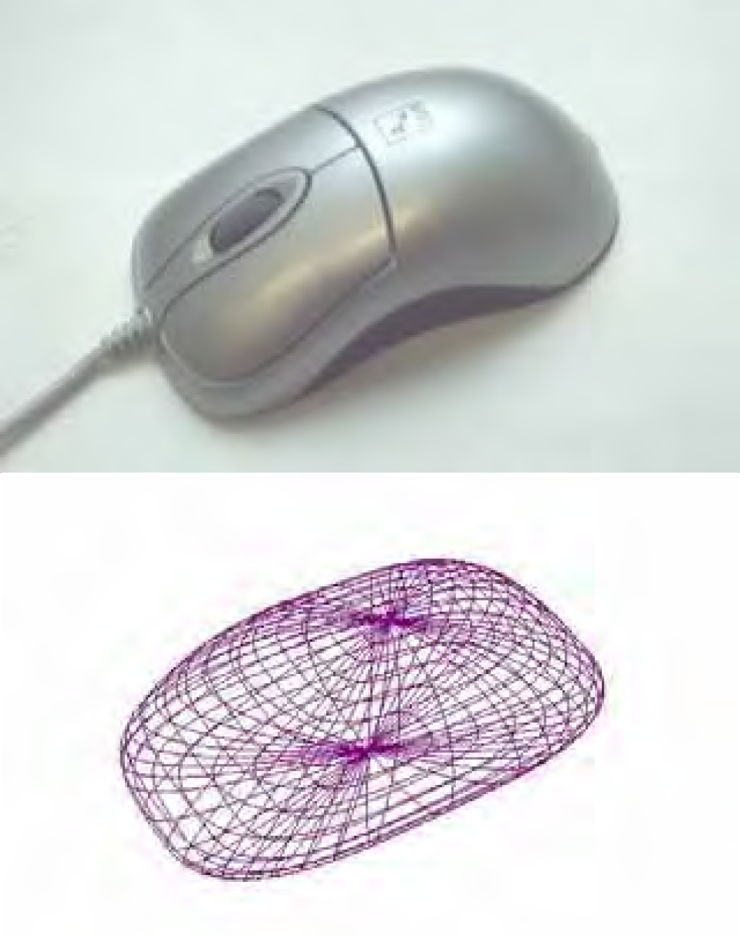
Example of a learned computer mouse approximated with a tapered Superquadric
The detection phase takes place in the cluttered everyday scene. The robot scans scenes in order to find the object of interest. Occlusion is likely to happen, so the detection method must be robust in the case of sparse data. A probabilistic approach is chosen for this purpose in a hierarchical two-level process. This helps keeping the computational effort low. The input for this phase is the range image of the current scene and the object model acquired in the shape-capturing phase (see Fig. 1).
First, a RANSAC-based low-level search is performed (Fischler, M.A. & Bolles, R.C., 1981) on sub-scaled raw data using a Superquadric recovery with Levenberg-Marquardt minimisation (Moré, J.J., 1977). A refining of the best low-level search result concludes this step.
Second, a high-level selection (pose verification) is performed because of possible faulty detections on the first level. Therefore, a ranked voting of the pose hypotheses (Parhami, P., 1994) is applied considering three constraints. Additionally to the standard quality of fit constraint, two constraints have been introduced to achieve superior results on sparse data from scannings with one view only: the number of points on the Superquadric surface and the number of the points inside the Superquadric (ideally zero, of course). A treatment on these constraints and a performance evaluation of the detection results is given in (Biegelbauer, G., 2006).
Using this hierarchical detection algorithm, fast and robust results are achieved in cluttered scenes. Fitting a known object (from shape-capturing) to local surface patches and verifying them globally within the refinement step, overcomes occlusions. For more details on this algorithm, please refer to (Biegelbauer, G. & Vincze, M., 2007).
Tracking the object
The shape of the object of interest (from shape-capturing) and its pose (from detection) are the initialisation for the object tracker. The tracker might then be used e.g. for visual servoing – exploiting the appearance of the object under the current illumination conditions. The Superquadric model is projected into the first camera image. Using Superquadrics, it is straightforward to compute the convex hull of the object, which provides the boundary of the projected object and within which interest points are searched. Each point found by the DoG algorithm is described using a SIFT descriptor. In contrast to using pre-computed points from a learning phase, the illumination conditions of the concrete situation are now used for finding and tracking the interest points. This means, the step from shape to appearance is performed now – in the actual scene. Using appearance information for tracking enables the use of rich texture information. Another possibility would be to use successive laser scans with subsequent pose estimations as described in 3.2, but frame rate issues is an argument against this approach. For usage of 3D tracking, the location of the detected interest points have to be computed in 3D model coordinates. Here, the strength of using Superquadric, raised in Sec. 2.1, stands out: Superquadrics describe closed surfaces, hence, the model coordinates of an interest point in the 2D image along with the information about the 3D pose of the object can be obtained by simply intersecting the ray of sight through the interest point with the model. This leads to the association of each 2D interest point (of the camera image) with a 3D model point (on the Superquadric).
The tracking loop works in the following manner: In each frame, interest points are detected in the neighbourhood of the points in the previous frame (tracking inherently assumes smooth and little movements of the object). The descriptions of the newly found points are compared with the description of points in the previous frames, delivering an association of new 2D points with old 3D model coordinates. These sets of associated points are input to the pose estimation algorithm. In our setup, we use the algorithm of (Lu, C.P. et al., 2000), because it is perfectly suited for this problem formulation. To overcome the problem of pose ambiguities, the algorithm of (Schweighofer, G. & Pinz, A., 2006) is applied. This way, pose estimation shows good results especially on planar targets that may occur in the case of box-like objects (see Experiment 1 in Sec. 4). Due to the fact that not all point matches are correct, pose estimation is done with a subset of points, using again a RANSAC-based approach. Wrong results can arise either because two points have a similar description or because a point does not belong to the object. The latter can happen as all interest points within the projected boundary are assumed to lie on the object, which is obviously wrong in the case of occlusion. The probabilistic approach now takes a couple of times a few of the strongest matches and computes the pose. For the computation of the pose, theoretically four points are enough, more points lead to increased accuracy. We are using four to eight points. Then, all remaining points vote for the correctness of this pose (or against it). Finally, the pose with the best voting result is taken, in case that there are equal votes, the mean of these votes are considered as best result.
The final task is to re-project all interest points of this frame again onto the model (in the new pose) and compute the object 3D coordinates again. The reason is that in this way, rotations can be handled: the overall number of points changes throughout the tracking sequence, new points appear and others disappear (they may get occluded or belong to a side of the object that gets invisible due to rotation, etc.). Using all interest points of a frame for matching with the next frame, no matter whether they assisted in finding the current pose, enables us to seamlessly integrate new points.
One drawback of this tracking approach shall not be concealed: Timing behaviour is rather poor as the detection of interest points is quite slow with the current implementation, especially on large objects. The disadvantage of faster detectors lies in the lower accuracy, which is unfeasible for tracking. Additionally, the pose estimation consumes a lot of time, which is due to the needed RANSAC iterations as well as the special consideration of estimating the pose from a planar target. However, as our main goal was to show a concept of separating shape and appearance, we did not investigate this matter further.
Calibration
Measurements in camera images are always very sensible to camera distortions. Therefore, the sensors have to be calibrated individually for the sake of accuracy, and afterwards, the two discrete coordinate systems of laser scanner and colour camera have to be registered onto each other in order to be able to compute the pose of the object (acquired with the laser scanner) in coordinates of the colour camera (for tracking). Providing all these variables for a given system (a robot or a sensor cell in the case of our experimental setup), allows the execution of an automatic sequence without user interaction between the different phases.
The calibration of the laser scanner is accomplished by the geometrical approach, where a three-dimensional calibration plate with markers (say, ellipses) on at least two different planes. Using the algorithm described in (Haverinen, J. & Röning, J., 2000), the pose of the laser plane and the extrinsic parameters of the laser camera can be calculated with this setup.
The colour camera for the tracking part is calibrated using the calibration tool Camcalb, introduced in (Zillich, M. & Al-Ani, E., 2004). Showing a calibration plate of ellipses in a few frames delivers the intrinsic camera parameters for calculating rectified camera images. Additionally, the extrinsic parameters for a given position of the camera plate are delivered, which helps for performing the last important calibration step: the coordinate matrices of the laser scanner and the colour camera are registered via transforming their respective world coordinate systems into one reference coordinate system.
Experiments
Fig. 6 and 7 show the three phases exemplified on the example of handling a rice box. The first row of Fig. 6 shows how shape-capturing of the original object (Subfig. 6a) is performed: After acquiring a range image (Subfig. 6b), a Superquadric is fitted (Subfig. 6c). The second row shows a cluttered scene (Subfig. 6d) of which a range image is taken (Subfig. 6e) where the Superquadric is located (Subfig. 6f). Fig. 7 represents the tracking phase.

Example 1: The first two phases of the automatic handling of an everyday commodity box. In the first row, the steps of the shape-capturing phase, in the second row the steps of the detection phase are depicted. Note that for shape-capturing, three sides of the object are visible (i.e. the maximum number for one view), whereas during detection, only two sides are in sight of the laser scanner

Example 1: Tracking phase (phase 3) of the automatic handling of an everyday commodity box. The starting pose (Subfig. g) is given by the detection phase, Subfig. h shows a matching example from one frame to another. The direction of the motion can be seen. The last Subfigures show some frames of the tracking sequence, the position of the Superquadric model (recovered by the interest point matches) is depicted in green. Note the dynamic occlusions first by the hand, then by the tin can and the mallet
The starting pose of the object (depicted as green mesh grid of the Superquadric) is retrieved from detection (Subfig. 7a). Subfig. 7b shows a matching example of interest points from one frame to another: The location of points from the first frame is depicted black, the current location white. A white line shows if corresponding points have been found and how much the respective point has moved from the last image. Note that some points have no line to a black point (on the right). This means they could not be matched – the reason is obvious in these cases: They were detected due to the occluding mallet shaft, therefore there is no point with a similar description from the previous frame. The last rows finally show some of the tracking frames (Subfig. 7c).
Table 1 summarises the parameters found by a single run of the shape-capturing phase of the rice box compared to the manually measured ground truth.
Summarised captured vs. true Superquadric size and shape parameter of the rice box of Experiment 1
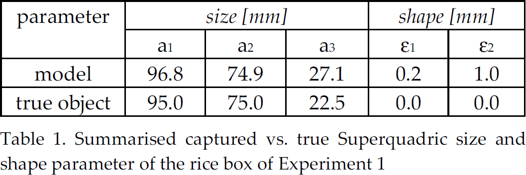
The comparison with the bottom line reveals that on the shortest side (a3), the recovery of the Superquadric is rather poor. However, due to the chosen tracking approach, this does not affect tracking very much. Using a line tracker would lead to a line search at the wrong position, resulting in an incorrect pose. Using interest points, however, tracking is not affected as the main surface for the points needed is independently useable for locating tracking points no matter how thick the box is assumed. Note the particularities of this example: First, the object of interest is partially occluded by the white bowl, the tin can and the mallet shaft. The occlusion by the mallet is furthermore dynamic throughout the tracking sequence due to the motion of the box. Additionally, the hand coming from the left also occludes (first dynamically, then statically) a part of the box. Finally, even the visible number of faces of the box changes from three to two. Nevertheless, the pose can be recovered. All this is possible because of the chosen tracking approach that is able to integrate newly appearing points into the process. However, in the case of 100% occlusion from one frame to the next, tracking could not be regained as this algorithm only uses information from the previous frame. A re-initialisation would be necessary. In other words, as long as enough (i.e. at least four) interest points can be linked with interest points found in the previous frame, tracking is not affected.
Fig. 8 and 9 show a second experiment we conducted, this time the object of interest is a cylinder in terms of a spray can of glue. Again, the first row of Fig. 8 depicts the shape-capturing phase, the second the detection phase, Fig. 9 shows some tracking frames.
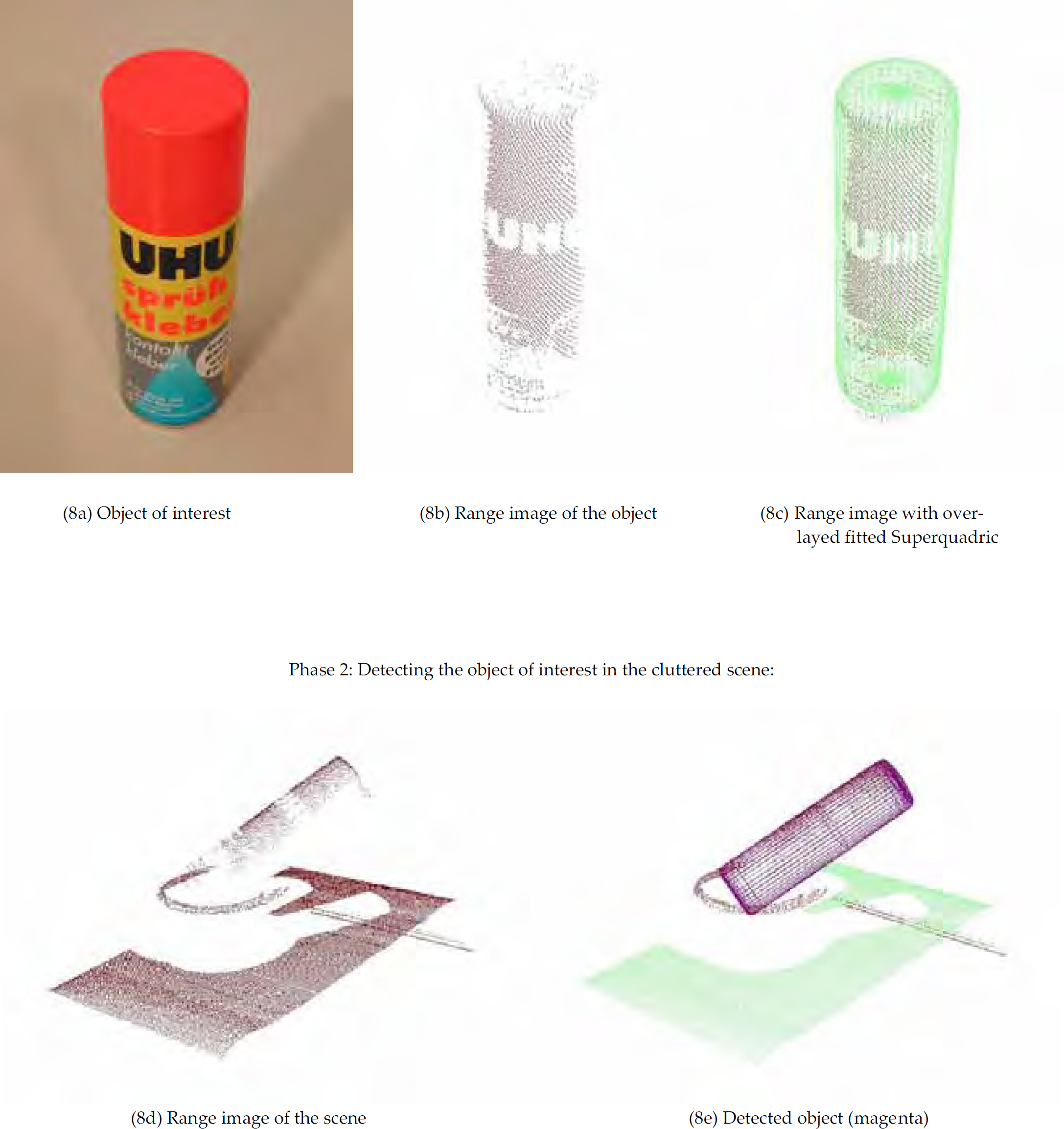
Experiment 2: First two phases of processing a spray can. Again, in the first row, the shape-capturing is depicted. Despite sparse data at the bottom of the can, a suitable Superquadric is fitted. In the second row, the detection in the cluttered scene can be seen
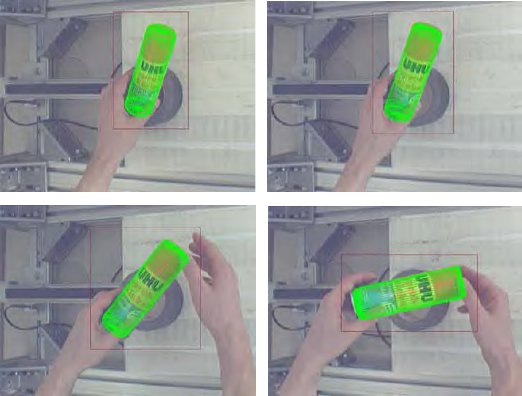
Experiment 2: Some frames of the tracking phase of processing a spray can. The motion of the object comprises translations and rotations
Table 2 depicts the parameters retrieved by the shape-capturing in a single run, again in comparison to the (manually measured) true values.
Summarised captured vs. true Superquadric size and shape parameter of the spray can of Experiment 2

This paper presents an automated approach using two vision sensors for shape-capturing, detecting and tracking of a convex object. The solution proposed is based on an approach for combining shape and appearance information in order to exploit both of their respective advantages. For modelling the object as well as for re-detecting it in a cluttered environment, shape is used due to its persistence under different illumination conditions. In particular, a hierarchical two-step method is introduced to robustly detect the object in cluttered scenes and from a single view. In the final phase, tracking, appearance information is exploited.
The rationale is that everyday objects have sufficient texture that can be exploited and the illumination conditions vary locally in a manageable way (as opposed to the different illumination conditions at the time of acquiring the model). With this integrated approach, the transition to appearance is taken in the actual scene and at the actual location of handling under constant illumination conditions.
The application that we have in mind is a robot that is able to find and handle an object that it has once been shown in an arbitrary environment. The experiments shown in Chapter 4 demonstrate that the usage of a laser scanner along with a colour camera for the tracking part is a viable vision solution for this purpose.
As further work, a faster implementation for the tracking part would be wishful. Our main focus until now was to provide the working integration of the three phases of the approach, but our implementation lacks of performance. Concretely, the pose estimation and also the location of the interest points are far away from working at camera frame rate, which hinders the use on a real robot at the moment. Necessary changes would comprise a faster implementation of an interest point detector and descriptor as well as a very fast and robust pose estimation with as few RANSAC iterations as possible.
Additionally to performance increase, another possible extension is the use of compositions of Superquadrics in order to handle more complex objects, such as the mallet that can be seen in Experiment 1. These objects may be expressed by a composition of several Superquadrics, which requires a learning process that parses subparts of an object automatically, such as shown in (Leonardis, A. & Jaklic, A., 1997).
To arrive at a more complete system it is necessary to study the accessibility and grasping approaches. While presently grasping points are linked to the captured object, it might be interesting to derive them from the generic object description or from the Superquadrics.
Finally, if it is detected that an object contains little texture or no good quality interest points can be found, the usage of additional cues for the tracking phase could be integrated. For example, features such as edges coulbe switched on automatically in such situations, e.g., (Vincze M. et al., 2005). As any tracker algorithm might be used within this concept, this would also further improve robustness.
Footnotes
6. Acknowledgement
This research work was supported by the Austrian Science Foundation grant S9101–N04.