
Abstract
It has been proven that fuzzy controllers are capable of controlling non-linear systems where it is cumbersome to develop conventional controllers based on mathematical modeling. This paper describes designing fuzzy controllers for an AC motor run mechanism. It also compares performance of two controllers designed based on Mamdani and Takagi-Sugeno with the conventional control scheme in a short track length, following a high disturbance. Fine and rapid control of AC motors have been a challenge and the main obstacle in gaining popularity in use of AC motors in robots actuators. This chapter reviews how use of intelligent control scheme can help to solve this problem.
Introduction
Until recently direct current motors were the most widely used actuators in industrial control systems. The popularity of the DC motors roots from DC power system in the US in early years (Chapman 2002-a). At present time, DC machines are still the best option for some applications. DC machines are the dominant electric drives in automotive, and aircraft industry as they operate by DC power systems. In robotics manipulators and machine tools, where accuracy, speed and torque are of prime importance, DC motors are the dominant drive, due to their particular characteristics such as speed controllability over a wide range, speed-torque performance, and high torque. On economic scale, the least effect of the complexity of the design of DC motors results in their high price (Bose 97-a, Cathey 2001-a, Chapman 2002-b).
AC motors are rugged, robust and low cost. The power electronics advances led to high power solid-state switching devices that can be employed in AC induction motors. Induction motors with solid state drive packages are preferred over DC motors for speed control applications that require only a gradual change in speed. Generally, besides cost advantage of such AC drives over their DC counterparts, these motors have less maintenance, smaller motor size, and improved reliability. However, these drives fall into category of general-purpose AC drives where speed can be regulated with less precision. These drives can be used in mechanisms in which the transient response and low-speed performance are not critical. Typical application areas are restricted to fan, pump, and compressors which require limited control flexibility. (Cathey 2001-b, Chapman 1999). There are similarities in construction of speed-controllable DC and AC motors. The angular speed of asynchronous AC motors may be controlled using variable frequency of AC power supply. The solution requires a very expensive electronics, overcoming the price of motor itself. In general, there are many constructions of AC motors and some are not faster in reaction as compared with DC motors.
More precise drives are needed for machine tools, robots, spindles, and the like. These mechanisms have more sophisticated requirements and as such until recently, these tasks were unachievable by AC motors, or required complexity in their design and were mainly the domain of DC motors. With advancement in microelectronics and appropriate control, these complexities are rapidly overcome. The precise control of sensitive parameters such as speed, position, acceleration, and torque is made possible by field oriented controllers or flux vector control AC induction motors. As such the gradual replacement of DC drives for high performance applications has already started. In design of flux vector control induction motors drives the concept of torque control in DC motors are replicated. Therefore, in an analogy with the action of commutators in DC machines in holding a fixed, orthogonal spatial angle between the field flux and the armature magneto motive force, in induction motors stator current is adjusted with reference to rotor flux to achieve independent control of flux and torque. This innovation began by Blaschke's work (Blaschke 1972) in Siemens Labs. Flux vector control AC induction drives decouple flux and torque components of motor current. This in turn improves speed-torque controllability of AC induction motors. Performance of Field oriented induction motors match that of DC motors. Intelligent control and in particular fuzzy logic control began by Mamdani's work (Mamdani 1974) in using fuzzy logic theory to control of dynamic process. Further research (Takagi 1985) examined suitability of fuzzy controllers in controlling complex process. This paper presents the refinement achieved by fuzzy control to the performance of flux vector induction motor. It will demonstrate that incorporation of fuzzy controllers will make the transient shorter and the response more stable.
Cart and Pendulum Problem
Design and implementation of a system is followed by vigorous testing to examine the quality of the design. This is true in the case of designing control systems. A classical system that is used to test quality and robustness of a control scheme is inverted pendulum. In recent years, the mechanism of an inverted pendulum on a moving cart has been used extensively and in many different types. The cart and pendulum mechanism has become even more popular since the advent of intelligent control techniques. This mechanism is simple, understandable in operation, and stimulating. It has a non-linear model that can be transformed into linear by including certain condition and assumption in its operation. For the above reasons, inverted pendulum's performance has become a bench mark for testing novel control schemes. In this chapter the focus is on the driving power in balancing the inverted pendulum which is an electrical motor. Traditionally, DC motors are used for this type of tasks. In this paper the focus is on AC electrical motors for producing the torque required for the horizontal movements of the inverted pendulum. A simplified control model for the AC motor is used which includes the motor's equivalent time constant as the crucial parameter in producing rapid responses to the disturbances. In the modeling of fuzzy controllers for the inverted pendulum, the input to the pendulum block is considered to be a torque. This torque is produced by an electrical motor which is not included in the model. That is, the torque is output of the motor. A disadvantage in this modeling is that the electrical motor dynamics is not built-in in the control system independently. On the other hand, not including the electrical motor in the control scheme of the pendulum mechanism provides the freedom to alter the electrical motor and examine the performance of the pendulum with different types of the drive. Here, a simplified model of an AC electrical motor is incorporated into the system. The electrical motor receives its inputs as current or voltage and produces a torque as output to control the balance of the mechanism. The new approach in modeling a fuzzy control system assists in achieving a number of goals such as: examining use of AC motors in producing rapid response, selecting sensitive parameters for an optimum high performance electrical motor capable to stabilize the inverted pendulum system, designing a Takagi-Sugeno type fuzzy controller, and comparing the effectiveness of inclusion of fuzzy controller along with the conventional control scheme.
Conventional Controllers & Fuzzy Controllers
The conventional approach in controlling the inverted pendulum system is to use a PID (Proportional, Integral, and Derivative) controller. In order to model the system the developer would have to know every technical detail about the system and be able to model it mathematically. Fuzzy Logic control (FLC) challenges this traditional approach by using educated guesses about the system to control it (Layne & Passino 2001). Passino states that differential equations are the language of conventional control (PID), while “rules” about how the system works is the language of fuzzy control (Passino and Yurkovich, 1998).
Fuzzy logic has found its way into the everyday life of people, since Lotfi Zedah first introduced fuzzy logic in 1962. In Japan, the use of fuzzy logic in household appliances is common. Fuzzy logic can be found in such common household products as video cameras, rice cookers and washing machines (Jenson 2005). From the weight of the clothes, fuzzy logic would be able to determine how much water as well as the time needed to effectively wash the clothes. Japan developed one of the largest fuzzy logic projects, when they opened the Sendai Subway in 1987 (Kahaner 1993). In this subway, trains are controlled by fuzzy logic.
Fuzzy Logic is a subset of traditional Boolean logic. Boolean logic states that something is either true or false, on or off, 0 or 1. Fuzzy logic extends this into saying that something is somewhat true, or not completely false. In fuzzy logic there is no clear definition as to what is exactly true or false. Fuzzy logic uses a degree of membership (DOM) to generalize the inputs and outputs of the system (Lin and Lee 1996). The DOM ranges from [0 1], where the degree of membership can lie anywhere in between.
The majority of Inverted pendulum systems developed using fuzzy logic, are developed using a two dimensional approach, where only the angle and angular velocity of the pendulum's arm are measured. The following research will show why this method is insufficient for the development of an inverted pendulum on a limited size track. To have an efficient fuzzy controller for an inverted pendulum, the system must also include inputs for the position of the cart that the pendulum is balanced upon and the velocity of the cart. Two-dimensional fuzzy controllers are very simple examples of fuzzy control research. Many of them will balance the inverted pendulum, but are not in control of the cart's position on the track. Adeel Nafis proposed a two-dimensional fuzzy controller to balance the Inverted pendulum on a track (Nafis 2005). Tests showed that the controller would balance the pendulum but neglected to control the position of the cart and eventually the cart's position would exceed the length of the track. Another FLC was proposed by Passino; again this cart had the same result as the previous FLC (Passino and Yurkovich, 1998). Control of the system requires that the cart holding the pendulum be moved by some mechanism. For simulation purposes, in this experiment a field oriented AC motor was used (Bose 1997-b).
Effect of Number of Inputs on Designing Fuzzy Logic Controllers
In a simple control mechanism there is one input and one output. Fuzzy Logic Controllers can have more than one input. Two-input FLC's are easy to implement and receive great performance responses from simulations. Layne (Layne & Passino 2001) modeled a fuzzy controller that had great performance balancing the pendulum but the cart's positioning was unstable, making it an impractical rule set for real life implementation. Two-input FLC's are the most commonly researched inverted pendulum systems. One of the most commonly researched types fuzzy controllers is two-input inverted pendulum systems. The 2-input system receives angle θ and angular velocity ω as its inputs. The system uses 5 membership functions for each input, and another 5 for the outputs which is the Force. The system consists of 25 (that is 5 to power 2; 52) rules. Table 1 shows the rule base for the inverted pendulum system. According to Table 1 a value of NL represents a negative large angle or angular velocity, and PL represents a positive large angle/angular velocity. As Table 1 indicates; if there is a situation where the angle is Zero (ZE) and the angular velocity is PS then the rule NS will be fired. Where, NL, NS, ZE, PS, PL are linguistic values of negative large, negative small, zero, positive small, and positive large.
Rule-base Matrix for the Inverted Pendulum

Rule-base Matrix for the Inverted Pendulum
A simulation that runs for 2 seconds is shown in Figure 1. The pendulum has an initial angle of 0.2 radians (dashed line). When the simulation is run, the angle of pendulum balances quickly, in about 1 second, but the position of the cart is not controlled (continuous line) so the cart's position will eventually drift off into the end of the track, even though the pendulum's arm is balanced.

Variation of angle θ (rad) and position X (m) of pendulum vs. time t (s)
The benefit of adding two more inputs to the system to control the X-position of the cart and the velocity of the cart will greatly benefit the stability of the system.
There is a cost for better stability; this is a greater computation time, and greater complexity in the model. The cost of adding more inputs increases exponentially with the number of inputs added. The above two-input system used five membership function for each input used; this resulted in a 25 (i.e. 52) rule base. By adding two more inputs to the system, the systems rule base would grow to 625 (i.e. 54) rules. Development time for a rule base this size can be very time consuming, both in development and in computational time. Bush proposed using an equation to calculate the rules, rather than taking the time to develop the rules individually (Bush 2001). The system was a 54 system with 17 output membership functions (OMF). The equation used was:

This equation results in values ranging between 1 and 17. This corresponds to the OMF that is to be used in the calculation of the output. The performance of the system using this approach is not consistent with that of the original simulation, given by the author of the above Equation 1 (Bush 2001). The force given to the cart holding the pendulum was found not to be enough to balance the pendulum and the system failed within a small amount of time. It can be concluded that this system would be a good starting point for one to base a large rule set on, but the system would need some tweaking of the rules and membership functions to get to balance the system effectively.
The final FLC controller that was modeled for simulation was a Takagi-Sugeno type fuzzy controller. All the previous FLC's modeled were of Mamdani type. A Takagi-Sugeno type fuzzy controller (Mathswork, 2002), (Liang & Langari, 1995), (Johansen et al. 2000), (Tanaka et al. 2003) varies from the traditional Mamdani type controller by using linear or constant OMF's instead of triangular, trapezoidal, Gaussian or any other method the developer decided to use. The system uses 4-inputs with only 2 input membership functions for each. This resulted in a 24, 16 rule system. The linear output membership functions (OMF) are calculate using the equation

Where Cn is the parameters of the OMF, and xn is the values of θ, ω, X and linear velocity V respectively. The system modeled here uses fuzzy logic toolbox of Matlab (Sugeno 2002).
Figure 2 is the result of the simulation. The pendulum is started with an initial disturbance of 0.2 radians. As shown, the fuzzy controller overcompensates for this initial disturbance and sends the pendulum's angle (dashed line) in an opposite direction in an attempt to balance it, this is the overshoot. It takes approximately 5 seconds for the pendulums arm to balance.

In adjusting the balance of pendulum angle θ (rad), and position X (m) changes with time t (s)
The motor chosen for the simulation is an AC motor. The motor is modeled, Figure 3, using field oriented control scheme (Bose 1997-b).


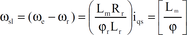


Where: τ r = L r /R r is the rotor time constant.

Magnetic Flux Control Scheme in Induction Motors
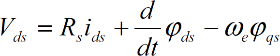
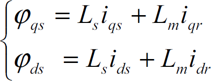
The field-oriented scheme makes control of AC machine analogous to that of DC machine. This is achieved by considering the d-q model of the AC machine in the reference frame rotating at synchronous speed ωe. In this model ids and iqs are current components of the stator current on d-q axis, where ids component is aligned with the rotor field. The rotor flux and torque can be controlled independently by ids and iqs, shown in Figure 4. The electric torque Te is proportional to the quadrature-axis current iqs, component of the stator current Is, and the rotor flux ψr can be controlled by the direct-axis current ids, of Is, where: Is = ids + J iqs.

iqs and ids components of Is on a d-q axis
The transfer function of this AC motor yields angular velocity (ω) as the motor shaft output. In the simulation, ω was easily converted into the force on the cart. The motor responded well, reaching its maximum force exerted on the cart in less than 2.5 seconds.
The simulation consists of four main components, the fuzzy controller, AC motor, the cart and the inverted pendulum, Figure 5. The cart passes the fuzzy controller four parameters θ, ω, X, V. Based on these four parameters the fuzzy controller outputs a voltage to the motor. The motor in turn calculates the force that will be exerted on the cart. The system then calculates the new values for parameters θ, ω, X, V and the cycle will be repeated.

Schematic diagram of fuzzy controller for the inverted pendulum
The fuzzy controller used in the simulation, with the AC motor included, is a 24 FLC as described above. The system runs identical to the 24 system only the settling time for the simulation, with the motor included, is larger. Figure 6 shows the results of the simulation using the same fuzzy controller as (Sugeno 2002) with the AC motor included in the simulation.

Variation of angle θ (rad) and position X(m) of the pendulum with time t(s)
The AC motor has a delay, where it takes the motor a given time to reach a maximum force. This in turn causes the simulation take longer to reach steady state. Parameters used in the simulation of the motor are listed in Table 2.
Parameters of the Modeled Motor

Figure 6 shows that it takes approximately 12 seconds for the pendulum's angle to become steady, and even longer for the cart's position to stabilize. The difference in the response time of this system can be found in the motor. The motor has a time constant which delays the motor's response time to an inputted voltage. A typical AC motor has a time constant larger than that of a DC motor. The shorter the time constant of the motor, the quicker the system will respond. Therefore, it can be expected that it takes longer for AC motor to balance the pendulum.
The simulation shows that the system responds well even with a motor attached to the system. The cost of implementing a motor into the simulation is response time for the pendulum to stabilize. Simulations done without the addition of the AC motor can not be considered for real life implementation because the motor is needed to investigate the response time that the system will observe in real life.
In a series of tests carried on without the use of fuzzy controller, it was revealed that the pendulum can hardly overcome any disturbances. If the disturbance is very small, it takes twice longer for the pendulum to balance again in an upright position.
Performances of vector control AC induction motors are comparable to that of DC motors; however, AC motors are rugged and low cost. Therefore, whenever possible, usage of AC motors will greatly reduce the capital cost of equipment and devices.
In this chapter design of a Fuzzy Logic Controller for a multi-input output system is described. It demonstrates a trade-off between precision which requires complex design and simplification which achieves less precise system. There is no absolute solution in developing fuzzy logic controllers. Designer of a FLC system must consider whether precision will be sacrificed for performance and simplicity. The 52 system developed in this work was very simple and computed quickly. The drawback of this initial design was that precision was compromised. The 24 system was also very simple and ran quickly but the performance of the system was not satisfactory. The settling time for the cart pendulum was required to be quicker. The 54 system was very complex and performance was slow, but if tuned correctly, a system of this size would be very precise.
Implementation of the system requires a high performance AC motor. Simulation results showed that the system would work for this type of motor. Having a smaller time constant in the AC motor would result in a shorter response time of the system. The FLC would need to be fine tuned for other types of motors.
With the AC motor implemented in the simulation model, the system did not react as well to high disturbances as it did when the motor was neglected in the simulation, or a DC motor was used. This indicates that the system will react well to small disturbances and be able to recover from them quickly. As the results indicates, in order for this system to handle large disturbances a motor with high performance dynamics need to be used that has a very small time constant. Use FLC made significant improvement to the controllability of the inverted pendulum by improving the response time.