
Abstract
This paper presents the latest results of a newly developed visual aid system for direct teleoperation. This method is extended to visual control to make an efficient teleoperation system by combining direct teleoperation and automatic control. On the one hand, an operator can conduct direct teleoperation with 3D graphic prediction simulation established by the VR technique. In order to remove inconsistencies between the virtual and real environments, a practical model-matching method is investigated. On the other hand, to realize real-time visual servoing control, a particular object recognition and pose estimation algorithm based on polygonal approximation is investigated to ensure a low computational cost for image processing. To avoid undesired forces involved in contact operation, 3D visual servoing incorporating a compliant control based on impedance control is developed. Finally, in a representative laboratory environment, a typical satellite servicing experiment is carried out based on this combined system. Experimental results demonstrate the feasibility and the effectiveness of the proposed method.
Keywords
1. Introduction
Currently, satellite servicing is mainly performed by astronauts controlling a spacecraft and a remote manipulator system such as Canadarm [1]. Due to the high cost and risks associated with astronauts, this kind of servicing has been limited to the most expensive satellites, such as the Hubble Space Telescope (HST) [2]. Teleoperation with space robots is considered one of the most promising substitutes for manned servicing. Several space robot teleoperation plans have been successively carried out, including ROKVISS [3], OLEV [4], and DEOS [5]. However, the communication delay, intermittence and limited bandwidth between the ground and on-orbit segments renders direct teleoperated control difficult [6]. Autonomous control seems to be an ideal choice to overcome time-delay effects on teleoperation. Unfortunately, completely autonomous control is limited by some key technologies [7], such as sensor information interpretation and artificial intelligence.
It is obvious that direct teleoperation and autonomous control have their own advantages and disadvantages. Direct teleoperation easily handles discontinuous operation and unexpected situations, and autonomous control gives stable and precise input in continuous operation. For safe and efficient operation in space tasks, in this paper a Visual Aid Teleoperation System (VATS) is presented based on the theory of satellite on-orbit self-servicing [8]. Compared with other satellite servicing systems, the virtue of this system is that when deployable appendages of satellites encounter malfunctions, the satellite has the capability of servicing itself with visual information of VATS, instead of using astronaut artificial servicing, while a teleoperator can flexibly choose an operation mode in VATS according to the specific space task. In particular, to avoid undesired forces involved in contact operation, a 3D visual servoing incorporating compliant control based on impedance control is developed.
The paper is organized as follows: in the next section, a system description and modelling are developed. Object recognition, pose estimation and visual servo control are described in section 3. Section 4 presents experimental results. The last section presents conclusions and suggestions for future work.
2. Description of Visual Aid Teleoperation System
Figure 1 shows the structure of VATS. It consists of two sides, the operator and the remote robot, which are connected through a local area network (TAN). In order to simulate the large time delay during space teleoperation, the artificial delay (about 5–7 s) is incorporated into the system by data buffer technology.

VATS
On the operator side, a virtual model of the remote robot and environment is created for the predictive display. A six-degree-of-freedom optical controller, the 3D connection space ball 5000, is connected to the computer for robot manipulation. The cyber glove, a fully instrumented glove that provides up to 22 high-accuracy joint-angle measurements, is used to control the robot hand through the transmission control protocol/internet protocol (TCP/IP) communication. The video-displayed computer displays the pictures of the hand and stereo cameras.
The remote robot side consists of a 4-DOF arm and a dexterous hand with 13 DOF [9]. The arm monitor camera (AC) is mounted on the third joint and the hand camera (HC) is mounted on the end effector of the robot arm. AC contains two cameras and is utilized as stereo monitoring with 8.5 mm baseline, whereas HC is used for recognizing the manipulated object and constructing the visual servoing scheme. A six-axis force/torque sensor produced by JR3 Inc., the JR3 sensor, is installed at the wrist of the robot to measure the contact force between the hand and the environment. The visual server is used for visual computation, video compression and transmission, whereas the robot server is used for controlling the real robot system and communicating with the operator side.
Satellite self-servicing is accomplished by shared control between human and robot. The servicing process can be composed of human control in free space and autonomous visual servoing control. In free space, with the help of a video display, the operator wears a glove with force feedback to manipulate the virtual hand, and uses the space ball to move the virtual robot. The input commands are sent to the remote executive real robot system if no errors happen in the virtual environment. When the robot reaches a specific position, autonomous visual servoing takes over control so as to avoid unnecessary tiny manual error input commands. To avoid exceptionally harmful forces being exerted on satellite and robot, a compliant control is established based on impedance control on the robot side.
3. Virtural Environment Modelling and Matching
3.1 Virtual Environment Modelling
It is very effective to simulate the planned tasks in the virtual environment before the real execution of the actual system. In VATS, the virtual environment modelling consists of geometrical modelling and kinematical modelling. The former is to build up by the 3D graphic model of the robot and environment, whereas the latter is to define the kinematic parameters based on the robotics. For the geometrical modelling the popular 3D modelling software ProE is used to model all geometrical solid objects. Then, these ProE files are used to generate the virtual environment by the functions of the OpenInventor software. The virtual environment model consists of the robot system, the hand, and the satellite body, as shown in Figure 2.

Virtual environment of satellite and robot
3.2 Modelling matching of virtual robot
It is known that model matching between virtual and real world is crucial for VR-based teleoperation [10]. However, to directly build a precise model of the real world is almost impossible. Thus, instead of reconstructing the whole environment, only a variable model is matched in the VATS, including robot and manipulated object matching. The virtual robot is matched using the real position sensor data from the robot joints; object matching will be discussed in relation to pose estimation below.
Before teleoperation is carried out, it is first necessary to make sure the situation of the virtual model is the same as that of the remote world, in order to synchronize sensor data. During the process of teleoperation, there might be some errors caused by missing command data. To reduce these errors, it is necessary to clear up the differences between the virtual and the remote robots. In VATS, the error between the virtual and remote robots is defined as

where Xv, Xc are the pose vectors of the virtual and real robots, respectively. When the error e is big enough, i.e., e ≥ E, where E is the threshold for updating, a warning message is generated to remind the operator to update the situation of the virtual robot to the real one, which can be executed in a manual or automatic manner.
4. Autonomous Vision Control of Manipulator
To meet real-time vision control objectives, various steps are required: first, the object of interest has to be detected and recognized in the image acquired by the camera. Once the object is known, it is possible to estimate the pose of the object over frames at video rate using 3D model-based pose algorithms. Finally, the output of 3D localization can be used to control the movement of the robot according to a predefined task. We now describe the three different steps.
4.1 Object Recognition
To simplify the image recognition computation, a planar cooperative object is designed and utilized, which is equipped with an optical marker as shown in Figure 3. The optical marker is composed of two rhombuses. The vertices of the rhombus are severed as pose estimation.

Cooperative object
The recognition algorithm is shown in Figure 4. For every image acquired by the camera, threshold segmentation is executed first to turn the grey image to a binary image. Then, the contours of the binary image can be obtained by a simple morphological operator. After image preprocessing the contours are encoded in chain code and the directions from one contour pixel to the next are tracked. Since chain code is an efficient compact representation of digital curves, the limited computing resource is saved and efficiency is improved. However, traditional chain codes are not invariant with boundary rotation. To improve rotation adaptability, a differential chain code is adopted.

Recognition pipeline data flow
As all borders have been retrieved from the image, the shape approximation representation is used for manipulating and analysing contours over the chain codes. Since the border data are vast, the Douglas-Peucker approximation algorithm [11] is executed first to simplify the representation time. Shapes are then recognized as cooperative objects if they meet the following three conditions:
The polygon is a parallelogram; The areas of two polygons are almost the same; Two corresponding vertices of two polygons are close, at 12 pixels.
4.2 Pose Estimation
Once the feature points are extracted from the image plane, a further step is required to determine the pose of cooperative object.
Given a set of correspondences between 3D reference points and their images, pose estimation can proceed to obtain the position and orientation of the calibrated camera with respect to the known reference points. For computation simplicity, the original point-of-world frame is identical to the original point-of-cooperative-object frame.
Instead of the commonly used perspective model, a weak-perspective model is used to link world points and their corresponding image points. The algorithm refines an initial pose estimate by iterating with a weak-perspective camera model to construct new image points. The pose estimation terminates when it reaches a converged image, the pose of which is the solution.
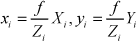
Using similar triangles theory, the relationship between the coordinates of an image point pi = (xi,yi) and its world point Pi = (Xi, Yi, Zi) can be determined as
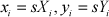
When the distances between any Zi are much smaller than the distance between Zi and the centre of projection, the weak-perspective projection model simplifies the projection equation by replacing all Zi with a representative Z˜ so that s = f / Z˜ is a constant scale for all points. The projection equations are then
Using weak-perspective projection, a reference point P0 in the world is chosen from which all other world points can be described as vectors:
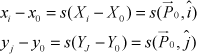
where s is a constant scale for all points. Define I and J as scaled-up versions of the unit vectors î and ĵ, so I and J can be further described as I = sî and J = sĵ. Thus, for each point,

where

where M+ is the pseudo-inverse of M and
Based on the obtained I and J, pose estimation can be described as follows. First, î and ĵ are estimated as I and J normalized, that is, scaled to unit length. By construction, these are the first two rows of the rotation matrix, and their cross-product is the third row:

The average of the magnitudes of I and J is an estimate of the weak-perspective scale s. From the weak-perspective equations, the world point P0 in camera coordinates is the image point p0 in camera coordinates scaled by s:

Eq.(8) is precisely the translation vector being sought. Since this initial pose estimation might be disturbed by various noises, by approximating perspective projection with weak-perspective projection, an iterated reprojected image method is utilized to reduce these noises. The algorithm proceeds as follows:
The object image is assumed to be a weak-perspective image of the object, from which a least-square pose approximation is calculated via the object model pseudo- inverse. From this approximate pose, the object model is projected onto the image plane to construct a new weak-perspective image. From this image, a new approximate pose is found using the least-squares method, which in turn determines another weak-perspective image, and so on.
For well-behaved inputs, this procedure converges to an unchanging weak-perspective image, whose corresponding pose is the final calculated object pose, which will be served as virtual manipulated object matching and visual servoing.
4.3 Vision Servoing Incorporating Cartesian Impedance Control
The pose estimated by the algorithm described above is used to realize position-based visual servoing. However, when the space robot makes contact with the manipulated object in visual servoing, some unnecessary forces are involved because of the existence of measurement error and calibration error. Thus, for safe operation, Cartesian impedance control is incorporated into position-based visual servoing, which constructs the spatial relationship of the target pose between the camera frame and the target object frame. The advantage of this combined approach is that the servo control structure is not only independent from the target pose reconstruction, but can also provide compliance contact and meet the desired dynamic relationship by regulating the end impedance of the robot.
As there is a torque sensor in each joint of the robot, the Cartesian impedance control is responsible for achieving the compliance of the robot. Figure 5 illustrates the structure of the Cartesian impedance controller.

Structure of Cartesian impedance controller
The aim of the Cartesian impedance controller is to establish a mass-damper-spring relationship, expressed by Eq.(9), between the Cartesian position Δx and the Cartesian force Fd.


where M, D, K are positive definite matrices representing the virtual inertia, damping and stiffness of the system, respectively x is the actual end-effector pose and xf is the reference trajectory, which is generated by the pose estimation algorithm described above to realize real-time position-based visual servoing.
The Cartesian force Fd from Eq.(9) is transformed into desired joint torques τ directly through Eq.(11):

where JT (q) is the transposed Jacobian. Thus, the impedance controller can be obtained by Eq.(12) with PD joint torque controller Gc(τ) and gravity compensation g(q) and friction compensation ff:

Since the pose estimation algorithm runs at too low a frequency for impedance control, robot motion control is performed through an inner-outer control loop running at a different frequency. As shown in Figure 6, the inner loop adopts point-to-point serial communication (PPSeCo) running at the frequency (1000 Hz in the experiments) to implement motion control. The higher frequency inner feedback loop guarantees stability and disturbance rejection. In the outer loop, the block named dynamic trajectory planner computes the trajectory for the end effector on the basis of the current object pose and the desired task. The input of this block is updated at the lower frequency (8 Hz in the experiments, due to delay of the camera capture and image processing).

hybrid visual servoing control
5. Experiments
Our experiment was carried out in a representative laboratory environment to deploy the folded solar panel of the satellite through the LAN.
The experiment task was based on the shared autonomy concept that distributes intelligence to both man and machine. The operator first makes a broad scan for the cooperative object, with the aid of a virtual simulation model and real-time stereo video feedback, and then moves the robot to an initial position for visual servoing. The initial position does not need to be precise as long as an optical marker of the cooperative object is available. When an optical marker is recognized, the operator hands over control of the robot to the visual servo controller. During the whole servicing operation, the robot is controlled automatically by the visual servoing algorithm, while the operator merely monitors it and overwrites the program command if necessary. At the end of the operation, the operator takes over the operation and does the final adjustment. Figure 7 shows sequence images obtained during the experiment. From top to bottom, the experiment goes through a sequence of behaviour: initial position, approach, grasp and push. Figure 7b shows the image processed by the vision system in the approach stage.

Push undeployed solar panel
Figure 8 shows the variation of the joint angle in the different control modes. In direct teleoperation, the operator uses a space ball to control the manipulator, which is easy to use in unexpected situations, but hard to operate precisely. As shown in Figure 8a, there is an oscillating joint angle in this control mode. Figure 8b shows the variation of the joint angle under visual control; ‘*’ represents the desired grasping position. In this mode, since there is trajectory planning in joint space, the motion of the manipulator is more stable than with direct teleoperation. Therefore, in this combined control mode, flexible and continuous operation is realized safely.

Joint angle in the different control modes
Figure 9 shows a comparison of joint torque between pure visual servoing and combined impedance controlled visual. It can be seen that the forces involved with pure visual servoing are larger than with visual servoing incorporating impedance control during the task. The experimental results verify that the proposed method can provide better compliance in visual servoing.

Joint torque comparison between pure visual servoing and impedance-controlled visual servoing
6. Conclusion
This paper has described a visual aid teleoperation system for satellite self-servicing operations. The major reason for developing the system was to explore the practicability of conducting satellite self-servicing with visual aid information. To realize a practical teleoperation system, a virtual environment model was established first, based on a VR technique. In order to remove the unavoidable model inconsistencies between the virtual and real environments, the virtual robot was corrected using the robot joint position sensor and the manipulated object was recognized by computer vision. Based on the virtual environment model and predictive display, a teleoperation scheme was developed, which enables the operator to conduct a direct operation without time delay. Then, a vision technique involved in the autonomous control system was investigated in detail. Particular object recognition and pose estimation was realized to ensure a low computational cost for image processing. For safe operation, Cartesian impedance control was incorporated in traditional visual servoing to provide contact compliance. Finally, a combined system of the direct teleoperation and the autonomous control was constructed. In this combined system, the direct teleoperation handles discontinuous operations like the start/end operation or latch operation, and the autonomous control handles the continuous deploying/stowing operation. This system showed great efficiency and can be applied in general satellite servicing tasks.
Footnotes
7. Acknowledgments
Supported by the grant of the National Science Foundation of China (No.61175121, 61202468), the grant of the National Science Foundation of Fujian Province (No.2013J05091, 2013J06014), Basic Scientific Research Special Foundation Project of Huaqiao University (No.11BS107), Promotion Program for Young and Middle-aged Teacher in Science and Technology Research of Huaqiao University (N0.ZQN-YX108).