
Abstract
Over the course of a decade-long research programme, the Korea Atomic Energy Research Institute (KAERI) has developed several remote handling systems for use in pyroprocessing research facilities. These systems are now used successfully for the operation and maintenance of processing equipment. The most recent remote handling system is the bridge-transported dual arm servo-manipulator system (BDSM), which is used for remote operation at the world's largest pyroprocess integrated inactive demonstration facility (PRIDE). Accurate and reliable servo-control is the basic requirement for the BDSM to accomplish any given tasks successfully in a hotcell environment. To achieve this end, the hardware and software of a digital signal processor-based remote control system were fully custom-developed and implemented to control the BDSM. To reduce the residual vibration of the BDSM, several input profiles, including input shaping, were carefully chosen and evaluated. Furthermore, a time delay controller was employed to achieve good tracking performance and systematic gain tuning. The experimental results demonstrate that the applied control algorithms are more effective than conventional approaches. The BDSM successfully completed its performance tests at a mock-up and was installed at PRIDE for real-world operation. The remote handling system at KAERI is expected to advance the actualization of pyroprocessing.
1. Introduction
Pyroprocessing technology is considered one of the most promising options for future nuclear cycles in the Republic of Korea. For the past few decades, the Korea Atomic Energy Research Institute (KAERI) has been focusing on the development of this technology, with an emphasis on not only the pyroprocess itself but also the system engineering aspects (including safeguards). To successfully realize innovative technologies, a remote system for safely handling radioactive material must also be developed. To conduct integrated system engineering studies, two representative R&D facilities have been constructed. Consequently, a significant amount of experience on the development of remote systems for these facilities has been accumulated.
In this paper, we address the development process of the most advanced remote handling system at KAERI, from its design to installation. In the next section, we provide overviews of the pyroprocessing technique and of the two KAERI facilities. We then describe in detail the most advanced remote handling system, the so-called ‘bridge-transported dual arm servo-manipulator’ (BDSM), along with issues that arise from facility constraints and their corresponding solutions. Later, we sequentially discuss the innovative features, configuration, control and performance of the BDSM, after which we conclude the paper with its current status and prospects.
2. Research Facility for Pyroprocessing
2.1 Pyroprocessing
Pyroprocessing is a process used for separating highly radioactive materials and transuranics (TRUs), such as Pu, Np and Am, from spent fuel in a high-temperature molten salt bath. The mixture fuels of separated TRUs and recycled (or depleted) uranium are loaded into fast reactors that burn highly radioactive long-lived isotopes while saving natural uranium resources. Therefore, pyroprocessing maximizes the utilization of limited uranium resources. Moreover, the inherent proliferation resistance of pyroprocessing is high because the process does not involve the isolation of specific nuclear elements at high purity. Thus, pyroprocessing reduces the amount of spent nuclear fuel and dramatically decreases the disposal load through the recycling and elimination of toxic waste, particularly long-life fission products in spent nuclear fuel [1].
2.2 PRIDE
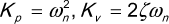
The efforts by KAERI to develop pyroprocessing technology led to the construction of two research facilities to demonstrate its technological capabilities. The first demonstration facility began in 2005 when KAERI had constructed the so-called ACPF (Advanced Spent Fuel Conditioning Process Facility), where remote handling operations for some key unit processes among integrated pyroprocessing technology has been undertaken and evaluated. In particular, an in-house servo-manipulator system called ‘BTSM’ (bridge transported servo-manipulator system), the precursor to BDSM, was deployed to cover dead zones that could not be accessed by mechanical manipulators fixed to the wall (Figure 1).
Several years later, another research facility for integrated pyroprocessing operations, the so-called ‘PyRoprocess Integrated inactive Demonstration facility’ (PRIDE) was planned to assess the feasibility of pyroprocessing in terms of integration among larger scale unit processes. PRIDE, which was designed to have a maximum treatment capacity of 10 tHM/yr, uses pure natural uranium or natural uranium with a surrogate material for the simulation of real spent fuel. As of August 2012, all process equipment installations have been completed and the facility is ready to begin its blank test. Figure 2 shows the main equipment layout at PRIDE, which is separated into two compartment cells: one of air and another with an Ar atmosphere. On the first floor, the Ar supply, the purification system, the exhaust system and a large transfer lock system were installed with some processing equipment that does not require an Ar atmosphere. On the second floor is an Ar compartment cell that includes most processing equipment and various remote handling devices, such as 34 master-slave manipulators (MSMs) and one BDSM. An Ar atmosphere, which presents a difficult task environment in terms of operation, prevents access to human operators; hence, all operations must be carried out in a fully remote manner. Before installing the processing equipment in an Ar compartment, thorough evaluations and revisions were repeated through both digital and real mock-up tests to reduce the equipment costs and likely errors during real operation.
Graphical view of ACPF from above.

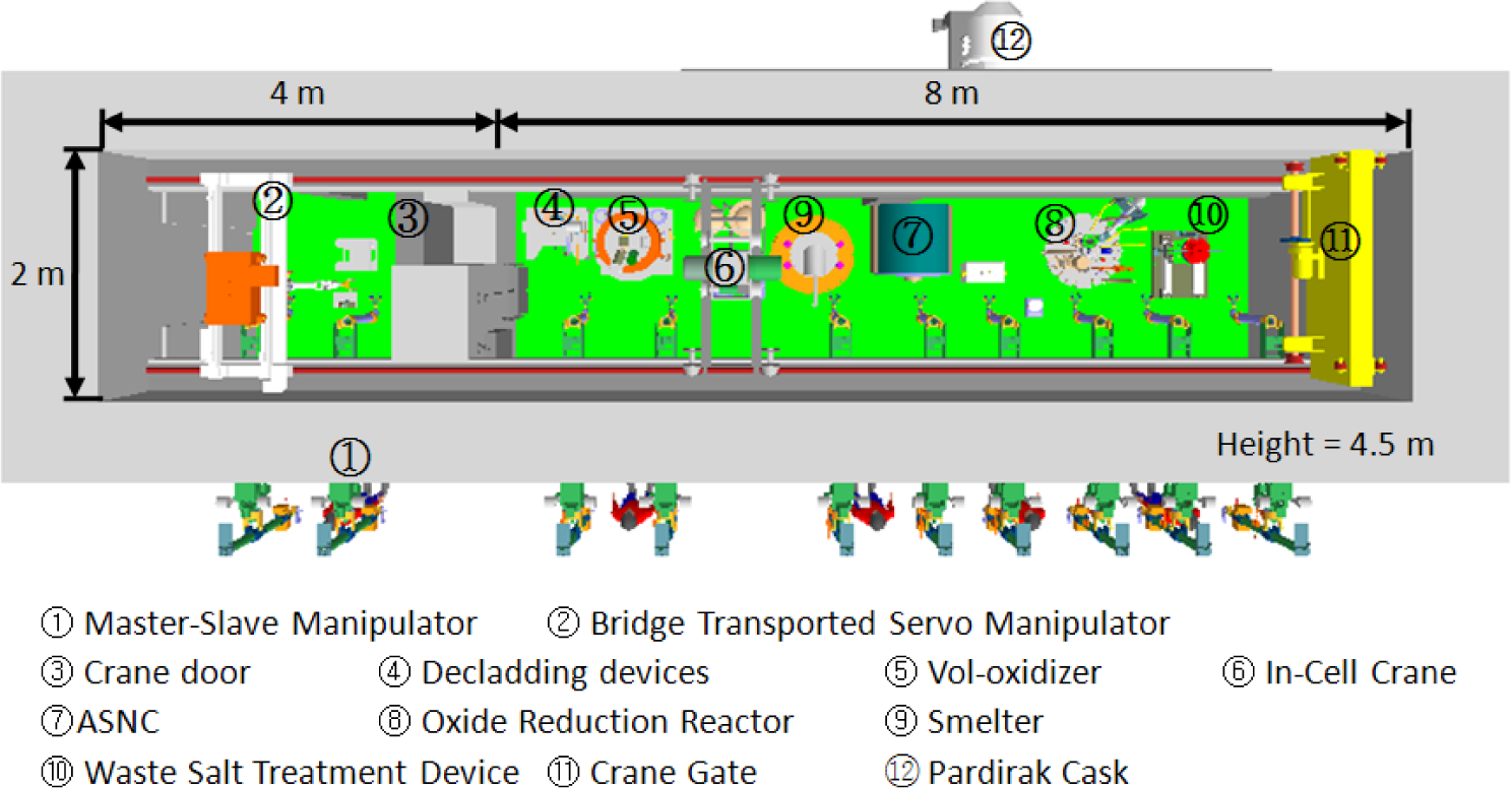
Top and front panoramic views (top) and cross section (bottom) of the PRIDE Ar cell, which is equipped with a dual-arm master servo-manipulator (A), a master transporter (B), thirty-four pairs of mechanical MSMs (C) and windows (D), an overhead crane (E), a bridge transport system (F), a dual-arm slave servo-manipulator (G), a feed-through (H), and a transfer lock system (I).
Specifications of force reflecting servo-manipulators.

The transport of materials between the two different compartments is performed using large and small transfer lock systems. The material between the unit processes in the Ar cell is shipped by remote handling systems, such as a crane, a MSM, a BDSM or auxiliary tools.
3. Remote Handling Systems
3.1 Overview
At the ACPF, a bridge-transported servo-manipulator system with one arm (BTSM) was installed. This has become one of the landmark events in the history of remote system development at KAERI [2]. Table 1 shows a comparison of the specifications of the BSTM with those of other commercialized servo-manipulators. These systems are currently used in several facilities for similar purposes - for example, the EMSM-2B installed at the Spallation Neutron Source (SNS) Target Facility, an accelerator-based neutron scattering facility at Oak Ridge National Laboratory [5]; MASCOT IV, at the Joint European Torus (JET) Tokomak [4]; Advanced Servo-manipulator (ASM), the first fully modularized and remotely maintainable servo-manipulator, for the Breeder Reprocessing Engineering Test (BRET) facility [3]. This type of manipulator system was originally developed for hot cells designed for the handling of radioactive materials, and it is widely used in areas such as fuel fabrication, the reprocessing of fuel elements, radioactive waste treatment and the decommissioning of nuclear facilities. To provide full access inside a cell, all these manipulator systems are mounted on a carriage such as an overhead Cartesian transporter or an articulated boom.
At PRIDE, a completely sealed Ar gas-filled cell contains all the equipment and relevant devices for integrated performance testing and the verification of the full pyroprocess flow. The equipment is operated and maintained in a fully remote manner because direct human access to the cell is not possible during operation owing to the Ar gas and nuclear material. As shown in Figure 2, the cell has dimensions of 40.3 × 4.8 × 6.4 m (L × W × H) and 17 windows (D) along the front wall. Each window workstation is equipped with a pair of gastight MSMs (C), which are commercially available (HWM, A110). These MSMs use a through-tube mechanism for the mechanical connection between the master and slave arms; thus, they provide a direct link between the operator and the manipulated slave arm. In addition to the commercial MSMs, the custom-designed BDSM, which is mounted on tracks inside the Ar cell, is also provided for complete access to all areas in the cell.
3.2 Configuration of the BDSM
The BDSM consists of dual-arm master manipulators (A), dual-arm slave manipulators (G), a bridge transport system for the slave manipulators (F), and a master transporter (B), as shown in Figure 2. The bridge transport system, which is composed of a gantry, a trolley and a telescoping boom, is configured for the positioning and orienting of the slave manipulators. It also has redundant drives to allow movement to a maintenance area in the event of a drive failure. An interface system is mounted on the bottom of the telescoping boom to allow for the easy attachment/detachment of the slave manipulator for maintenance or its replacement with special-purpose robotic tools.
After developing the second prototype of the BDSM introduced in [8], we modified some components - such as the boots and protection cover - to prevent contamination, and devoted much effort to enhancing the control system. As part of this effort, we replaced the Windows-based controller with a digital signal processor (DSP)-based system to provide more reliable and real-time control. Below, we briefly introduce the BDSM that is applied practically in the PRIDE facility.
Figures 3 and 4 show the computer-aided design (CAD) model of the BDSM. With the aid of transporter systems, both the master and slave arms can work inside and outside the cell, respectively. Unlike the conventional master servo-manipulator placed in the control room, the master manipulators in this study are carried by a transporter; this enhances the cooperative work performance between the MSM and BDSM operators with the aid of direct communication. Furthermore, the operator can manipulate the master arm while viewing the equipment through an operating window or camera system. Work performance is thus improved in terms of time and success rate compared with that of camera viewing alone in the control room.

Overall constitution of the out-of-cell BDSM.

Overall constitution of the in-cell BDSM.
With the exception of their link lengths, drive systems and end effectors, the master and slave manipulators have identical kinematic structures. Each arm of the master and slave manipulators is designed as a 6-degree-of-freedom (DOF) serial link mechanism with all revolute joints in an elbow-up posture, and the power to each joint transmitted through a cable from a corresponding motor mounted on the base frame. A counterweight is mounted on the forearm pitch link for the simultaneous balancing of the link structures during both forearm pitch and upper-arm roll motions. The slave manipulator can hold a 25-kg object in any pose, whereas the master manipulator reflects forces of up to 5 kgf to the operator.
3.3 Design issues
PRIDE is a refurbished KAERI facility that was originally used for other purposes. For this reason, it has limitations in its dimensions. Therefore, designing a remote handling system in consideration of the size constraints is crucial. In particular, designing the telescoping boom of a bridge transporter is difficult because of the limited height of PRIDE. The telescoping boom moves the manipulators vertically owing to the extension and retraction of a number of tubes. It must have a 2,000 mm stroke in the fully extended state; this is so that the manipulators can reach the bottom with a convenient posture and very short height (<1,450 mm) in their fully retracted state, because the trolley system that includes the telescoping boom must be able to cross over the bridge girder via an overhead crane (Figure 2(E)) and come to rest inside the transfer lock system for repair. This requirement can be expressed as the following optimization problem to determine the number of tubes and their lengths:


where Ftnobj is the objective function to be minimized; the stroke, by definition, is the difference between the fully extended and fully retracted lengths; stroked is the desired stroke (2,000 mm) given by constraint requirements; Lret is the fully retracted length, which is also given by the constraint requirements; and N is an integer that denotes the number of tubes.

Two states (fully retracted and fully extended) of the equally extensible telescoping boom.
The telescoping boom was designed to be equally extensible; thus, every tube travels the same length. In Figure 5, assuming that each tube has the same length L, the fully extended length, fully retracted length and stroke, are expressed as:


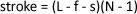
where L is the length of each tube; f is the overlapped length when the telescoping boom is fully extended; N is the number of tubes in the telescoping boom; and s is the length of the stopper.
An important design issue for the telescoping boom is managing the power and signal cables from the trolley box connectors to the manipulator interface connectors, depending upon the motion of the telescoping boom. The simple principle of synchronized cable-boom movement is shown in Figure 6. The cable length remains constant regardless of the degree of boom extension; thus, if the boom is retracted, the cable management system accommodates the longer cable due to the retraction of the boom as the moving pulleys descend by the retracted length divided by 2n (where n is the number of moving pulleys). This cable storing system is implemented passively. The ballast weight loaded on the moving pulleys always keeps the cable taut by gravity while the power motor simply pulls or releases the innermost tube with a manipulator system. Such a passive movement system is problem-free because it does not use sensors or actuators.

Principle of synchronized cable-boom movement.
3.4 The DSP-based control system
The BDSM is a complex robotic system with 35 DOFs: 28 for the dual-arm master and slave manipulators, 4 for the slave transporter, and 3 for the master transporter. Therefore, accurate and reliable servo control is essential for the BDSM to accomplish any given task successfully. To achieve this end, the hardware and software of the DSP-based control system were fully custom-developed and implemented. By upgrading a prototype control system that used a high-precision multimedia timer callback function [8], a DSP-based control system equipped with a real-time operating system (OS) was developed. The DSP-based control system handles hardware interruptions directly and offers a control frequency of over 10 kHz. In addition, the OS offers great operational stability because it only performs control-related tasks. Booting is completed within 1 or 2 s. Furthermore, most maintenance tasks may involve the replacement of only abnormal hardware modules.
The DSP-based control system was designed based upon modular concepts. Each module controls the 4 axes of master-slave joints where two master joints and two slave joints are linked to each other. The system integrates CPU, analogue out, encoder/counter, and digital input/output modules (Figure 7). Among other components, the overall control system hardware consists of a host PC, nine DSP-based 4-axis motion control units, motor drivers, a manual console, and a pendant. The servo motors adopted in the master-slave servo-manipulator are operated in the torque control mode to realize bilateral force reflection control. In contrast, the bridge transporter and hoist are operated in the velocity control mode using the manual console and pendant. The manual console and pendant display the system status and control the motion of the transporter system.

DSP-based control system architecture.
The DSP-based motion control software is physically divided into two components: the user interface software running on the host PC, and the firmware software running on DSPs. The PC software was developed in a Microsoft Visual Studio programming environment because of its popularity, ease-of-use and compatibility with Windows XP. The program displays the system status and updates several control parameters by communicating with the DSP units via an Ethernet link. It also includes options for switching control modes. The DSP software consists of real-time kernel libraries, communication modules, hardware interface functions and control algorithms. The firmware was written in the ANSI-C language with Code Composer StudioTM, an integrated software development environment provided by Texas Instrument.
The host PC and target DSP units communicate with each other using two Internet protocols: a User Diagram Protocol (UDP) and a Transmission Control Protocol (TCP). Control commands concerning the control modes and control parameters are transmitted to the target DSPs using a TCP for lossless communication. In contrast, all of the motion data of the manipulators and the bridge transporter is transmitted to the host PC using a UDP for real-time data transmission.
During the development stage, we used a JTAG interface, as defined by IEEE Std.-1149.1, for programming and debugging the DSPs. Once a program is successfully tested and verified, it is permanently recorded to the target DSPs through Ethernet links by using custom-developed firmware update software. The real-time control algorithm was implemented in the firmware software, and is composed of three steps: boot up, main task and control task. At start up or after a reset, a booting program stored in the flash memory of the DSP unit initializes the DSP internal registers and DSP interrupt service table. After initialization, the program enters into an idle loop waiting for user input. The master-slave control is activated by pressing a button installed on a handle of the master manipulator.
4. Control performance
4.1 Bridge transporter
The bridge transporter resembles an industrial crane in terms of moving an object to a destination position as quickly and safely as possible. As shown in Figure 2, PRIDE has lengthy dimensions across which the BDSM must travel. The frequent repetition of forward and backward movements of the bridge transporter is required to properly position the dual-arm manipulator and perform a given manipulation task. Therefore, the bridge transporter should move rapidly but also stably so as to reduce travelling time and help the dual-arm servo-manipulator perform tasks largely unaffected by the behaviour of the bridge transporter. The bridge transporter is usually controlled by a human operator merely clicking a few pendant buttons, as in an industrial crane. The maximum velocity is simply set to a target value and the control performance is solely influenced by the issue of how to transit between travelling and stop states. An abrupt transition naturally causes the system to undergo large vibrations, which tend to accumulate damage in the system. Therefore, the effect of velocity transition in the bridge transporter should be investigated.
The bridge transporter must be able to move a heavy structure (approximately 3 tons) with high inertia (approximately 4 kg·cm2). A velocity path following the characteristics of the bridge transporter was tested to optimize the profile. Without a control loop, an abrupt velocity change might induce an extremely large vibration in a heavy structure. Nevertheless, a closed loop control system was not used in the bridge transporter because a feedback control system for sensing distance and velocity is expensive and problematic when the sensors malfunction in a highly radioactive or hazardous environment. The bridge transporter is operated in the velocity control mode, which is the same mode of operation used for industrial cranes.
To reduce vibrations and increase the BDSM lifetime, various velocity profiles were investigated. Since a step velocity profile induces a large vibration, the inclination angle of the velocity - i.e., the absolute value of acceleration - must be reduced to have a gentle slope. However, a gradual slope accompanies time lags from the departure point to the steady-state and from the steady-state to the point of complete termination. Thus, the velocity incline should be determined by balancing the trade-offs. We investigated step, trapezoidal and S-shaped profiles, in addition to two kinds of input-shaping profiles. The first three are commonly used as practical velocity profiles in the industry, whereas the last two are recently introduced to efficiently achieve two incompatible objectives, viz. rapid and stable responses without extensive control efforts.
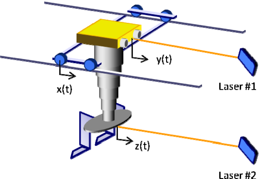
Sensor locations for data acquisition.
To measure displacements at three points for each profile, two laser sensor signals and an encoder signal are recorded, as shown in Figure 8.
The bridge transporter displays the following characteristics, depending upon the velocity profile. Given a step velocity command profile without a time lag between the stop state and the target velocity, the actual response shows a very short time lag but a large vibration relative to the other profiles shown in Figures 9 and 10. To distinguish the velocity command and actual output profiles in Figure 9, the latter profiles were drawn with a 100 mm/s offset. Although the vibrations at the girder bridge of the transporter are small, those at the tube end far from the girder are magnified a few times, as shown in Figure 10. The latter vibrations affect the structural integrity, accumulate damage and, ultimately, cause failure. To reduce such harmful vibrations, other profiles were tested. Given trapezoidal and S-shaped commands with a 1 s time lag, the output results show a dramatic reduction in vibrations compared with the step profile, although more time is required to arrive at the target velocity. A problem arising from a long time lag can be overcome by using a shaped input command. Input shaping control is a method used to impose an impulse sequence to reduce the resonance frequency of a system. This method has been further investigated and extended by numerous researchers since its original development [6, 7]. The two input shaping commands were generated as follows:


where ti and Ai are the time and amplitude of an impulse in the input shaper, respectively; ωn is the natural frequency; and ζ is the damping ratio. Equations (7) and (8) are used to design the input shapers, called the ‘zero vibration’ (ZV) and ‘zero vibration-and-derivative’ (ZVD) input shapers, respectively.

Velocity profiles of the bridge transporter: trapezoidal, S-shaped, input shaper-ZV, input shaper-ZVD, and step.

Offset displacement depending upon the velocity profile: trapezoidal, S-shaped, input shaper-ZV, input shaper-ZVD, and step.
In terms of suppressing vibrations, the ZV and ZVD input shapers are superior to the other profiles. The offset displacement in Figure 10 indicates the difference between the theoretically calculated moving distance from a velocity command profile and the distance measured by a laser sensor. This offset displacement can occur owing to clearance between mechanical elements, assuming no slip between the wheels of the bridge transporter and the rails. Although the encoder signal in the step profile in Figure 10 shows a slight slip, it is negligible compared with the offset displacements at the girder and tube end.
The two input shapers show a moderate offset displacement during movement that returns to almost zero when stopping. The above results were applied to a jog operation of the bridge transporter, in which users could select a trapezoidal, S-shaped (default), or a ZV- or ZVD-input shaping profile.
4.2 Manipulator
The servo-manipulators listed in Table 1 - which were developed for use in highly radioactive environments - do not employ sensors on the slave side owing to the high probability of sensor failure and maintenance difficulties. Therefore, the control architecture is constrained to only use available measurements, such as master/slave motor positions and motor rates. In addition, because the master and slave manipulators are mechanical replicas, each pair of joints can be controlled without any coordinate transformation. Commonly used in this kind of application is the following bilateral control structure based upon two PD controllers, in which both the master and slave are equipped with local position tracking controllers to ensure that each manipulator tracks the other:

where α is the force reflection ratio; τfm and τfs are additional torques needed to overcome the frictional resistances; and Kp and Kv are the proportional and derivative control gains, respectively. The control gains are usually tuned for good performance in the no-payload condition. The steady-state position error linearly increases as the payload increases because the PD controller does not include integral action (Figure 11). As the payload dependent errors feed into the master control loop and amplify the force reflection ratio, the master manipulator can provide the feedback force to the operator. To use the controller, the operator manually manipulates a selector switch or push buttons installed in a pendant and linked to force reflection ratios, such as 0, 1/2, 1/4, 1/8, etc. No force feedback mode can be activated when α = 0. However, the controller has a deficiency of noisy force feedback even in free motion owing to the poor tracking performance. This in turn causes operator fatigue.

Steady-state errors of the PD controller with different payloads.
In this work, we substituted a time delay controller (TDC) for the conventional PD controller in the slave manipulator of (9) to achieve good tracking performance and practical gain tuning. A TDC provides a systematic gain tuning methodology in which the control gains are determined by selecting the natural frequency and damping ratio of the desired error dynamics without the dynamic models of the system [9, 10]. A TDC utilizes time delay estimation, which involves the use of recent data to estimate the uncertain dynamics and disturbances in the system. The TDC cancels out the undesired dynamics and disturbances and substitutes for them the desired dynamics given in terms of the reference model. Therefore, the controller can be designed without an accurate model or any use of model information. In addition, the modelling error has little effect on controller performance.
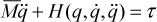
The TDC is briefly summarized below. The dynamic equation of the robot manipulator is given by:

where τ is the actuator torque; and q, q̇ and q̈ denote the joint angle, joint angular velocity and joint acceleration, respectively; M (q) is the inertia matrix; C(q, q̇) are the Coriolis and centrifugal forces; G(q) is the gravitational force; and D(q, q̇) represents the friction and unmodelled nonlinearities. In equation (10), let M (q) be approximated by M̅ (q) as a constant matrix; the equation can then be rewritten as:

In accordance with the idea established by the computed torque control approach, the control input is computed as:


where q̈d is the desired joint acceleration; e = qd – q is the position error; and Kv and Kp are the derivative and proportional gain matrices, respectively. Substituting equations (13) and (14) into (11) yields the closed-loop error equation:
PD-type gains can be determined from an error dynamics with a desired natural frequency of ωn and a desired damping ratio of ζ as:
In the TDC, the uncertainty at the present time t is usually assumed to be very close to its value at time t – L in the past for a very small time delay. If so, H(t) can be estimated as:

By combining equations (13), (14) and (17), the TDC law is obtained as follows:

This control law is computationally efficient because it does not require any calculation of a robot model. The closed-loop stability condition can be found in [9, 10]. The performance of the original TDC has been enhanced by adding a switching action that uses an integral sliding surface to overcome the windup problem [12], a gradient estimator to reduce errors of time delay estimation [13], and a terminal sliding mode for the fast convergence of time delay estimation [14] to control the loop.
The gain tuning procedure of the TDC is quite straightforward and can be summarized as follows:
1) Determine the target error dynamics in equation (15) by selecting the desired natural frequency ωn and a desired damping ratio ζ, as in equation (16).
2) Select the time delay L as the sampling time t of the control system. L is commonly chosen as the smallest achievable value to minimize the time delay estimation error in equation (17).
3) Tune M̅. M̅, which determines the stability and performance of the TDC, could be tuned by two methods: (1) a stability condition that requires nominal information about M [9–11] or (2) a trial-and-error method where M̅ is increased from small positive values during the verification of the control performance [13, 14].
The master-slave manipulator system used in the experiment is shown in Figure 12. The parameters of the manipulator dynamics were assumed to be unknown and thus were not used. The time delay L was selected as 0.001 s because a sampling frequency over 1 kHz did not meaningfully affect the degradation of the system performance. The angular position of the master-slave system was measured by counting the encoder pulse signals. The angular velocity and angular acceleration were calculated by numerical differentiation after passing them through a low pass filter.
Master-slave dual-arm manipulator system.
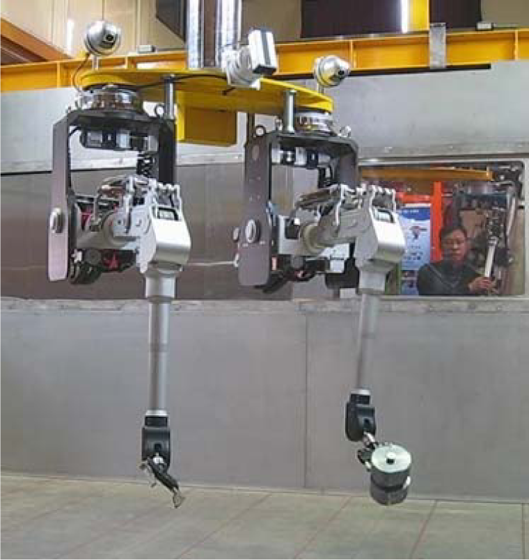
Figure 13 shows the reference trajectory following results with a variation of parameter M̅. We selected the control gains so as to force the desired error dynamics to be critically damped (ζ = 1, ωn = 10 rad/s). Initially, we chose a small positive value for M̅ - in this case 0.1 - and then increased it to 0.3 while verifying the control performance. Thus, we could easily tune the best value of M̅ after a number of trial experiments.
Reference trajectory following results with variation of parameter M̅.
To demonstrate the robustness of the TDC against payload variations that cause uncertainties in C (q, q̇) and G(q) in equation (10), we first tuned the controller in the no-payload condition, as shown in Figure 13, and then verified the performance by using the same gains with a maximum payload of 25 kgf. For this analysis, the performance of the system with the TDC is compared with that of the system with the PD, as shown in Figure 14. The reference input, which is designed on the basis of jerk-bounded trajectory planning, also applies to both controllers with the same values. The system with the PD controller has a relatively large transient and steady-state error because the controller has fixed gains and cannot compensate in the event of changes in load or unpredictable disturbances. Unlike the PD controller, the tracking performances of the TDC with or without payload are quite similar. This suggests that the TDC effectively handles the uncertainties due to parameter variations.
Figure 15 illustrates the master-to-slave position tracking performances along axis 1 during the handling of a 10 kgf load. The three tracking indices - position, velocity and acceleration - are quite similar across both master and slave manipulators despite the small errors and overshoot. However, an operator can deal with these errors without significant degradation because the operator is located in the teleoperation loop.
Comparison of the performance of the PD and the TDC.

Position tracking results during axis 1 motion where the slave arm with a payload of 10 kgf follows an arbitrary motion of the master
BDSM installed at PRIDE.
4.5 Installation
The installation of the BDSM at PRIDE was a challenging issue. Given the limited dimensions of the cell, the girder bridge had to be separated before being carried in and assembled. The rails on which the BDSM is mounted must have millimetre-precision for efficient BDSM movement. Cover boots to prevent contamination from radioactive material and salt fumes were specially designed and put on at the manipulators and telescoping boom. To provide the operators with a closer view, cameras mounted on the wrist of the manipulator were specially designed for remote replacement and tested for view angle and position for comfort. As of September 2012, the BDSM is on standby for real process operations following completion of the installation and blank test, as shown in Figure 16.
5. Conclusions
The remote technology of KAERI has matured along with its recycling facilities. In every aspect, from design to installation, development of the remote handling system BDSM had to be closely related with the processing equipment and pyroprocessing facility. Such R&D needs initiated a systematic and cooperative study among pyroprocessing researchers and facility designers. The technological know-how accumulated through ACPF and PRIDE construction was even used to design pyroprocessing equipment in terms of remote handling feasibility. Most equipment components were remarkably improved to become remotely operable. The two R&D facilities for pyroprocessing technology not only provided remote system developers at KAERI with challenging goals, but also helped them comprehensively understand an integrated technology that fuses together various disciplines. The culmination of this work was the development of an innovative BDSM. The new remote system technology is currently being put to test in real process operations at PRIDE. We expect that remote handling systems - including BDSM - will play an important role in advancing the realization of pyroprocessing technology.
Footnotes
15. Acknowledgments
This work was supported by the Nuclear Research and Development Programme of the National Research Foundation of Korea (NRF) and funded by the Ministry of Education, Science and Technology (MEST)