
Abstract
This paper presents an auto-climbing robot for cleaning the elliptic half-shell of National Grand Theatre in China. The robot consists of a climbing mechanism, a moving mechanism, two cleaning brushes and supporting mechanisms. The mechanism and unique aspects are presented in detail. A distributed control system based on CAN bus is designed to meet the requirements of controlling the robot. After that the emphasis for discussion is on the motion realization which includes climbing and cleaning movements. The robot independently climbs and descends in the vertical direction and cleans in the horizontal direction. It takes the circling tracks as supports for climbing up and down between strips and moving horizontally along one strip around the ellipsoid. For system design and control purposes, the dynamic models of the climbing and cleaning processes are given applying of the Lagrange equation. Furthermore the force distribution of the front and rear supporting mechanisms is computed in a way that ensures the safety of the climbing process. In the end, the successful on-site tests confirm the principles described above and the robot's ability.
Introduction
Climbing robots feature the special working environment and mobility against gravity. They are useful devices adopted in a variety of applications such as reliable nondestructive evaluation (NDE) and diagnosis in some hazardous environments, welding and manipulation in the construction industry especially of metallic structures, cleaning and maintenance of high-rise buildings.
Note that in the U.S.A and Asia, a great amount of high-rise buildings are emerging in modern cities. Every architect prefers to present the new buildings to the world with his own characteristics. That is why the number of high-rise buildings with complicated shapes is increasing worldwide, as shown in Fig. 1. However these external cladding walls require constant cleaning. As a result, even skilled workers with safety ropes have difficulties in climbing those buildings and currently almost of them are still cleaned manually, as shown in Fig.2.

Typical environments for cleaning

The current solutions for building cleaning
The development of walking and climbing robots offers a novel solution to the above-mentioned problems. Because of the current lack of uniform building structures, wall cleaning and maintenance of high-rise buildings is becoming one of the most appropriate fields for robotization. A cleaning robotic system can make the automatic cleaning of high-rise buildings possible and relieve cleaning workers of their hazardous work.
This paper presents an autonomous climbing robot for cleaning the elliptic half-shell of National Grand Theatre in China. The theatre is 54 m high, and the long axis and short axis of the ellipse on the ground are 212 m and 146 m respectively, as shown in Fig. 3.
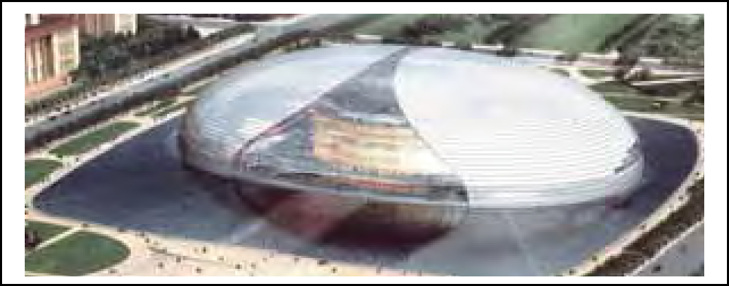
National Grand Theatre of China
The surface walls consist of more than 20,000 glass and titanium planks. The total outer surface covers 36,000 m2, with 6,000 m2 of transparent glass walls, and 30,000 m2 of Titanium walls. The wall consists of 54 strips altogether, with each strip having a different height and sloping angle. The outer surface holds some LED-lamps, decorating belts which are 300mm wide and 140 mm high. A track which was originally designed for the needs of construction and maintenance circles the half-ellipsoid along the rim between every two strips. In order to achieve a half-ellipsoid, each plank is constructed at a different size and is connected to its surrounding planks at an angle. The major challenge in designing a robotic system is the ability to overcome all of the obstacles in vertical and horizontal on the surface and finish cleaning automatically.
The possible cleaning solution for this complex architecture is to use a semi-automatic arm to send the cleaners to the building top, as shown in Fig.4. Some special designed windows are on the top for cleaning workers to get out of the building. This solution is highly expensive. Meanwhile the cleaning operation is still dangerous, tough and exhausted for human beings in mid-air.
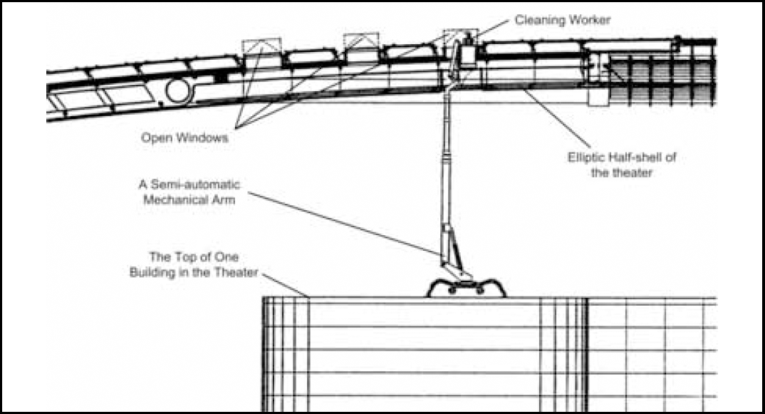
The possible cleaning solution
In this paper based on analyzing the characteristics of the working target, a new kind of auto-climbing robot is proposed, which is used for cleaning the spherical surface of the National Grand Theatre in China. This paper is organized as follows: Section 2 gives an overview of the previous work on curtain wall cleaning robotic systems. Following this, robot's mechanism and its unique aspects are presented in section 3. Section 4 introduces the process of climbing from one strip to the next and cleaning within one strip thoroughly. In Section 5, the dynamics of the locomotion based on Lagrange formulation are presented. After that, a new approach to path planning for wall-cleaning robots is presented considering movement security, cleaning efficiency and the percentage of cleaning coverage. On-site experiments and conclusions are given to confirm the principles described above and the robot's ability to work on a spherical surface in the end.
In the last two decades, a lot of different prototypes were designed for building cleaning purpose. In Japan, a kind of pneumatic robot was developed for cleaning the embassy of Canada (Nishigami, M., Mizushima, T. 1992). The robot moves and cleans the glass curtain wall in vertical direction, but it cannot walk sideways. Another smart window cleaning robot was proposed in Japan recently (Miyake, T.; Ishihara, H. 2003). It attaches window glass by suction cup and is actuated by two driving wheels. The whole prototype suited for using at home or in an office, is quite light and compact.
In Europe, SIRIUSc (Elkmann, N. et al., 2002) is a walking robot for the automatic cleaning of tall buildings and skyscrapers. This robot can be used on the majority of vertical and steeply inclined structured surfaces and facades. However, it cannot move sideways on its own and has to be positioned this way by a trolley on the top of the roof. Another robot mentioned in the same paper, was developed for the Leipzig Trade Fair in 1997. It was the first facade cleaning robot for vaulted buildings worldwide. In 2003, a climbing robot for industrial kitchen cleaning was proposed based on the cooperation between a leader company in household appliances and the PMAR group from University of Genova (Cepolina, F. et al; 2003). It is a pity that no mechanical realization and real application is presented even if authors mentioned this prototype can implement cleaning effective and it might also be used as a platform for other purposes.
Since 1996 the group at Beihang University has been developing a family of Sky Cleaner autonomous climbing robots (Zhang, H. et al., 2006) for glass-wall cleaning. The first model has only limited dexterity and cannot work on a vertical wall. Because it lacks a waist joint, the robot is unable to correct the direction of its motion. The following robot is easily portable and has a cleaning efficiency of about 75 m2/ hour. But the stiffness of the construction is very low, causing a small distortion during cleaning and climbing activities. Sky Cleaner 3 is a commercial product driven by pneumatic cylinders and attaches to glass walls with vacuum suckers. However, it cannot be used on any other type of walls.
An automatic gondola for cleaning glass windows was developed, which takes the Beijing Hotel in China as its operation target (Zhang, H. et al., 2006). The robot can fulfil the work of attaching on the wall, cleaning the glass window, reclaiming, purifying and recycling the sewage. Like SIRIUSc, this robot is supported above by cables from the sub-system so that all of the movements are passive and actuated by the following cables. In 2005, a cone glass-curtain wall cleaning robot was proposed for the airport control tower's daily cleaning service (Wang, W., Tang, B. 2005). According to motion-functions-dispersed principle, the new cleaning device met the requirements of the lightness, high reliability and safety.
Although some robots have been developed for wall cleaning, most of them can only deal with planes with inerratic shape. To the best of our knowledge there is currently no similar robot that can be used directly for cleaning a building with elliptic half-shell like National Grand Theatre in China. Our eventual goal is to free workers from the dangerous environment and develop dexterity, intelligent cleaning robotic systems to meet the requirements of real application.
System design and realization
Prototype design
Based on the features of the building construction mentioned above, an auto-climbing robot is designed as shown in Fig. 5. The robot independently climbs and descends in the vertical direction and cleans in the horizontal direction. It takes the circling tracks as supports for climbing up and down between strips and moving horizontally along one strip around the ellipsoid. Special sliding-rods are designed to be the medium between the track and the robot in order to avoid the safety problem caused by the robot directly grasping the track. The rods can only slide along the tracks passively but cannot be detached from the tracks, as shown in Fig.6.

Prototype design

Sliding rods
The robot consists of the climbing mechanism, the moving mechanism, two cleaning brushes and the supporting mechanisms. In order to adapt to the different planks' sizes on the building, the robot has to be quite big in order to realize all necessary movement functions. As a result it is 3 meters long, 1.5 meters wide and 0.4 meter high. The total weight of the robot is 100 Kg.
The degree of freedom of the robot (Zhang, H. et al., 2005) is demonstrated in Fig. 7. There are 25 joints altogether, 17 out of which are active and are actuated by respective DC motors. The joints are categorized as follows:

Degree of freedom
Linear active motion between the main frame and the auxiliary frame (P9);
Linear active motion of two rod-clutches on the main frame (P1, P2);
Linear active motion of two rod-clutches on the auxiliary frame (P8, P10);
Linear active motion of the front and rear supporting mechanisms (P6, P15), and passive rotation of wheels on the front and rear supporting mechanisms (R5, R10);
Three rotary joints (R1, R2, R3) and three prismatic joints (P3, P4, P5) on the front driving-wheel set.
R1 represents the active rotation of the driving wheel; R2 is the passive rotation of the wheel paired to the driving wheel; R3 is a passive rotation which is used for the wheels to adapt the angle to the track; P3 is a linear passive motion used for the front wheel set to adapt its relative position to the track; P4 is the linear active motion to lift or lower the wheels; P5 is used to clamp the track between the wheels.
The joints on the rear wheel set are similar to those of the front wheel set.
Linear active motion of the left and right brush-sets (P7, P14), and active rotation for the brushes (R4, R5).
The main body of the robot is made up of two frames: the main frame and the auxiliary frame, as shown in Fig.8. Other functional parts are all mounted on these two frames. In order to keep the weight light while maintaining a dexterous movement mechanism, considerable stress is laid on a light yet stiff construction.

Mechanical construction of the robot
The auxiliary frame can slide along the main frame. This linear movement is actuated by the DC motor and the belt, both of which are mounted on the top of the main frame (Fig. 9). Two rotating brushes mounted on the auxiliary frame move up and down and rotate for cleaning when the robot moves sideways along the tracks.

The climbing mechanism design and realization
The auxiliary frame has a shape like an n encircling the main frame to ensure safe and reliable movement (Fig. 10). A special sliding bar made of polyethylene is designed to create a sliding-mate between the two frames thus saving the weight of the linear guidance which is usually used for this kind of structure.
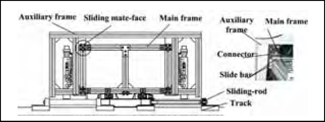
Sliding-mate between two frames
Two pairs of clutches, shown in Fig. 11, are on the main frame and the auxiliary frame respectively. Their function is to grasp the sliding-rods which safely slide along the track without becoming detached. The sliding-rods are designed to be the medium between the track and the robot in order to avoid the safety problem caused by the robot directly grasping the track. The climbing process is implemented by alternating two pairs of clutches the hold and release of sliding robs on tracks to enable displacement. As a safety constraint, the displaces along the longitude of the half-shell as one clutch holds up and the other is free and moves on. A DC motor is embedded in the mechanical clutch to allow for a very light structure.

The clutch mechanism
A front supporting mechanism and a rear supporting mechanism with the same structure as the clutches are used to adjust the orientation of the robot and support the body on the surface. There are two supporting wheels on the tip of the mechanism in order to increase the area of interaction and avoid damaging the surface (shown in Fig 12). The wheels give a passive turning motion when the robot climbs in the vertical direction.

The supporting mechanism
A front and a rear wheel sets which are used to provide the sideways driving force for the robot when they are clamped on the tracks are also installed on the axis of the main frame. The rear wheel set can move passively along the middle axis of the main frame in order to suit the various sizes of the planks caused by the arc shape of the building surface (as shown in Fig. 13). A linear guidance connects the whole set to the main frame, which permits a passive sliding. The lifting DC motor can lift and lower the whole set to adapt to the height of the track.

Mechanical structure of the wheel set
When the robot is working on such a half-ellipsoid, obstacles and the friction make it almost impossible to attach a safety cable to the robot from the theatre top. As a result, a special mechanical structure named the abdominal plate was designed to solve the safety problem. While a set of clutches hold the sliding-rod to avoid falling down, the abdominal plate on the robot are interposed between two little wheels on the sliding-rod to avoid capsizing out of the wall (shown in Fig. 14).

The abdominal plate
A distributed control system based on CAN bus is adapted to robotics system, as shown in Fig. 15. The system is divided into 6 parts, five CAN bus control nodes and a remote controller (Zhang, H. et al., 2005).

Control system
The PCM-9575 industrial PC is the core part of the control system. It is a new EBX form factor 5.25“ single board computer (SBC) with an onboard VIA Embedded low power Ezra 800 MHz. This board can operate without a fan at temperatures up to 60 degrees Celsius and typically consumes fewer than 14 Watts while supporting numerous peripherals. This SBC includes a rich set of interfaces for future hardware. Its design is based on the EBX form factor that supports the PC/104-Plus interface for ISA/PCI module upgrades.
A PCM3680 card is used as a communication interface with PC/104-Plus interface for the main node and the other CAN nodes. The responsibilities of the main computer node include receiving orders from the remote controller, planning operational processes, receiving feedback information from other nodes, and giving orders to other nodes. The other four lower-level nodes are responsible for receiving orders from the main computer node and directly controlling respective joint motors.
It is important for the control system to realize precise position control when the robot moves vertically from one strip of planks to another. On the other hand, some joints such as brushes and clutches only need an ordinary on-off control mode. As a result, two kinds of CAN nodes, both designed by us and mainly based on the P80C592 micro-chip, are included in the control system in order to meet the requirements of functionality, extensibility and low cost. Each node is in charge of special functions in which all the related sensor signals are included. To make the control node extensible, it contains enough I/O resources which allow for the easy attachment of sensors and sensor processing equipments. At the same time multiple process programming capability is guaranteed by the principle of CAN bus. Controlling and monitoring the robot is achieved through the digitalized CCD camera and a wireless graphical user interface (GUI) which allows for an effective and friendly operation of the robot.
Movement realization includes two parts: climbing movement and the cleaning movement. The robot can climb in the vertical direction and clean in the horizontal direction.
Climbing movement
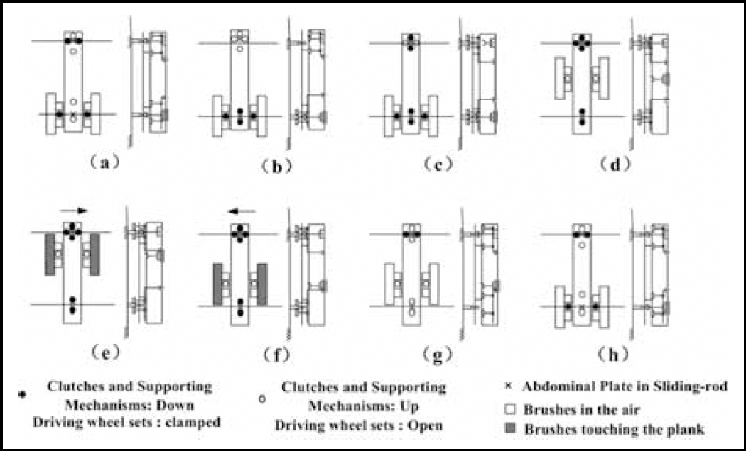
The climbing process is implemented by alternating two pairs of clutches the hold and release of sliding robs on tracks. Fig. 16 shows the process of climbing from one layer to the next step by step. In this process the brush sets are all in the up-state (no contact with the plank).

Plan of the climbing motion
The robot is in its home state: clutches on the main and auxiliary frame are all in the down-state to hold the sliding-rod on track 1 and on track 2 respectively; the abdominal plate is inserted in both sliding-rods; the two supporting mechanisms are all in the up-state.
Clutches on the auxiliary frame are raised, and the auxiliary frame is pulled up along the main frame.
The motion of the auxiliary frame stops when the clutches on it are right above track 2. Then the clutches are lowered to grip the sliding-rod.
Clutches on the main frame are raised; the front supporting mechanism touches down on plank 1.
The main frame moves up. When the abdominal plate is out of the sliding-rod on track 1 and the rear supporting mechanism is above plank 1, the main frame stops moving and the rear supporting mechanism touches down on plank 1.
The front supporting mechanism is raised, and the main frame continues to move up. When the front supporting mechanism is above plank 2, it touches down on plank 2.
The upward movement of the main frame does not stop until track 3 is detected by the front ultrasonic sensor. Then the front or rear supporting mechanisms are adjusting to position the robot parallel to plank 2. Afterwards, the main frame moves up to insert the abdominal plate into the sliding-rod on track 3.
The motion of the main frame stops when the clutches on it are right above track 3. Then the clutches are lowered to grip the sliding-rod on track 3. The robot is now in its home state again, and the process of climbing up to the next strip is over.
Fig.17 demonstrates the process of the cleaning movement within one strip.
Cleaning movement
The robot is in its home state.
The clutches on the main frame are lifted. The main frame moves up until track 1 is right under the rear driving-wheel set. Then the rear wheel set is lowered and the driving wheels are clamped onto track 1.
The main frame then moves down until track 2 is right under the front wheel set. Then the front wheel set is lowered and its driving wheels are clamped onto track2.
Because the clutches on the main frame are in line with the front wheel set, the clutches can be put down to hold the sliding-rod on track 2. Then lift the clutches on the auxiliary frame.
The auxiliary frame moves up until the upper edge of the brush-set is in line with track 2. Then the brush-set is lowered till it touches the plank. After the front and rear driving wheels are actuated simultaneously the robot can move to the right to clean the upper half of that strip.
After a circle of one half-strip has been cleaned, the brush-set moves down to the lower half of that strip, and the robot moves left to clean that half.
When the cleaning of that strip is finished, the brush-sets are lifted. Then both driving-wheel sets unclamp from the tracks and are lifted.
After that, the clutches on the auxiliary frame move down with the frame to track 1, and are lowered to grasp the sliding-rod on track 1. Now the robot is back in its home state again.
There are two kinds of dangerous cases during the climbing process, one is falling down and the other is capsizing out of the wall. The climbing robot has to be safely attached to the wall surface and has to overcome its gravity. The attachment plane should adapt to the complicated shape of the building. That is the first difference between a wall climbing robot and an ordinary robot walking on the ground (Zhang, H.; et al, 2005).
From the safety point of view, the process of climbing from one strip to another is very dangerous because the robot has to adapt to the outer shape of the building. The major challenge in cleaning movement is the ability to adapt to the different planks' sizes on the same strip. Additionally, this robot has to be quite big in order to realize all necessary functions. Therefore, in designing this mechanism and its controls, an equilibrium between safety and size has to be reached. This is way the dynamics design of the autonomous robots should optimize the overall robot weight.
Climbing analysis
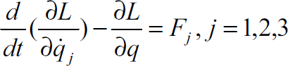
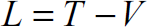
Here we only discuss the process of ascending because the process of descending is similar. There are two phases during the process of ascending. First the auxiliary frame moves along the main frame, then the main frame ascends. The first phase is safe due to the clutches holding the sliding-rod and the abdominal plate inserted into two sets of sliding-rods. We will only discuss the second part in detail. The climbing dynamics of the robot are analyzed by the application of the Lagrange equation, described as (1), (2). Where L is the Lagrange function; q is the generalized coordinate; Fj is the generalized forces; T is the kinetic energy of the system; and V is the potential energy;
The kinematics model of the robot during climbing is shown in Fig. 18. Where oxyz is the world coordinate and the xoy plane is paralleled with the lower plank; and o′x′y′z′ is the reference coordinate fixed at the robot's body, with the x′ axis along the width of the frame, the y′ axis along the length and the z′ axis pointing vertically upward from the main frame. The two points of o and o′ are superimposed. The parameters are shown below.

The kinematics mode of climbing movement
r3 is the vector from the centroid of the auxiliary frame to the centroid of the mainframe;
r4 is the displacement of the front supporting mechanism; r5 is the displacement of the rear supporting mechanism;
β is the rotating angle of the mainframe according to the x axis, it is also named θx; φ is the rotating angle of the mainframe according to the z′ axis; α is the angle between the lower plank and the gravity vector;
R is the length of the clutches; L0 is the length of the mainframe; L1 is the distance between the front supporting mechanism and the centroid of the mainframe; L2 is the distance between the rear supporting mechanism and the centroid of the mainframe;
m1 is the mass of the mainframe; m2 is the mass of the auxiliary frame; J1cx, J1cy and J1cz are the moments of inertia of the mainframe; J2cx, J2cy and J2cz are the moments of inertia of the auxiliary frame;
Fr3 is the driving force for climbing; FFB is the driving force for the front supporting mechanism; FBB is the driving force for the rear supporting mechanism; M is the driving moment generated by the supporting mechanisms.
While climbing up, the front and rear wheel sets do not work so that the freedom in the x direction is not available. The freedom of climbing is three and can be described with the generalized coordinate q (r3, φ, β). There are two situations that should be avoided during this process. One is the non-brace that means neither the front supporting mechanism nor the rear one works; the other is the excessive-brace that means two supporting mechanisms work together. There are some constraints between r4, r5 and β, as shown in (3).

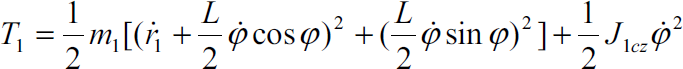
According to (2), the kinetic energy of the mainframe is T1, as shown in (4).

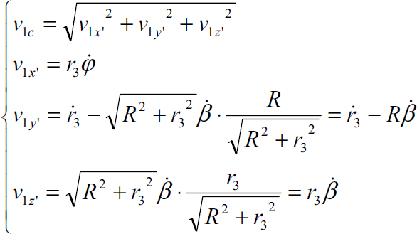
We can get v1c, as shown in (5). As a result, the kinetic energy of the mainframe is shown in (6).

Since the zero potential energy position is on the horizontal plane passing though point o, the potential energy is described as (7).

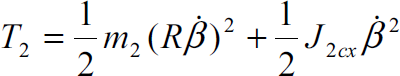
In the same way, the kinetic energy and the potential energy of the auxiliary frame are calculated in the following (8), (9).

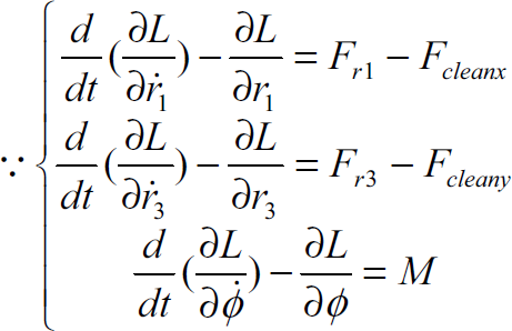
In (10), all these results are inserted into the Lagrange function.

According to the Lagrange equation (11), the dynamic characteristics of the climbing movement are reached, as shown in (12).


When the front supporting mechanism is working, M is described as (13); when not, it is described as (14).

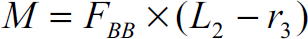
As mentioned before, the supporting mechanisms are used to adjust the alignment of the robot and to support the body on the surface, as shown in (13) (14). In order to meet the requirements of safety, the touching pressure between the supporting mechanisms and the surface should be sufficient. That means the interaction conditions on the surface are stable. On the other hand it is also quite dangerous if the force is too great as this could crush the planks. As Nlimit (1500N) is the bearing capability of the plank, at the beginning of the designing process, it is very necessary to make sure the touching pressure is smaller than this limitation.

According to the analysis above, the front supporting force is described in (15). Where l is the negative of r3 in order to compute the distribution of the force.
When all the conditions shown below apply, R=150mm, L0=2800mm, G1=60kg, G2=40kg, L1=200mm, L2=L0/2=1400mm, α=0–90°, the force distribution is gotten, as shown in Fig. 19(a). Here the range of l should be within [–1000, 700] mm due to mechanical constrains. According to the same process, the distribution of the rear force is shown in Fig. 19(b). From these two figures, we can see the maximum of the supporting forces meet the requests, as shown in (16). The force distribution of the front and rear supporting mechanisms is computed in a way that ensures the safety of the climbing process.


The front and rear supporting pressure distributions
The kinematics model of the cleaning is shown in Fig. 20. Cleaning movement is relatively safe since the robot cannot fall down and capsize out of the wall as mentioned above. However each plank is constructed at a different size, there is still one dangerous robot-locking case between two tracks during the process due to the difference between the velocities of the front and a rear wheel sets when they are clamped on the tracks and providing the sideways driving force for the cleaning. After ignoring the same parameters in the climbing process, the different parameters are shown below.

Kinematics model of cleaning
Where r1 is the displacement vector of the front wheel set; r2 is the displacement vector of the rear wheel set;
Fr1 is the driving force for the front wheel set; Fr2 is the driving force for the rear wheel set; Fcleanx 3.110. tcleany are the resistant friction during the cleaning movement; L is the distance of the strip.
The front and rear supporting mechanism do not work during the cleaning so that the freedom in the Z and θx are not available. Meanwhile there are some constraints between r1, r2 and φ, as shown in (17). In a result, the freedom of cleaning is three and can be described with the generalized coordinate q (r1, r3, φ).

According to Fig. 21, the kinetic energy of the mainframe is T1, as shown in (18).

Analysis of velocities
Since the zero potential energy position is on the horizontal plane passing though point o, the potential energy is described as (19).

In the same way, the kinetic energy and the potential energy of the auxiliary frame are calculated in the following (20), (21).


According to the Lagrange equation (22), the dynamic characteristics of the climbing movement are reached, as shown in (23).

Dynamics models of movement realization are concluded. All of the results are important for system design and the design of the controlling mechanism for this climbing robot.
Path planning and the path tracking strategies for mobile robots are highly dependent on the work target characteristics. Area-covering operation is a common and useful kind of path planning also named complete coverage path planning (CCPP), which requires the robot path to cover every part of the workspace (Hofner, C., et al, 1995) (Pirzadeh, A., et al, 1990). The CCPP is suitable for wall-cleaning robots due to robotic operational characteristics. This project works with the concept of the limitation of the work area, so that the constructional consistency, continuity and accessibility are satisfied within any subdivided area. Consistency means the curtain-wall has the same structure within one area; continuity means that the area is a plane or a curve with a sufficiently large radius; and accessibility means that any spot on the wall can be reached. There are three guidelines for subdivision according to boundary rule, medium rule and obstacle rule.
Using these three guidelines, the global workspace can be subdivided into several regions, as shown in Fig. 22. We are dealing with six work space regions. The material of Region I and IV is glass; other areas are Titanium.
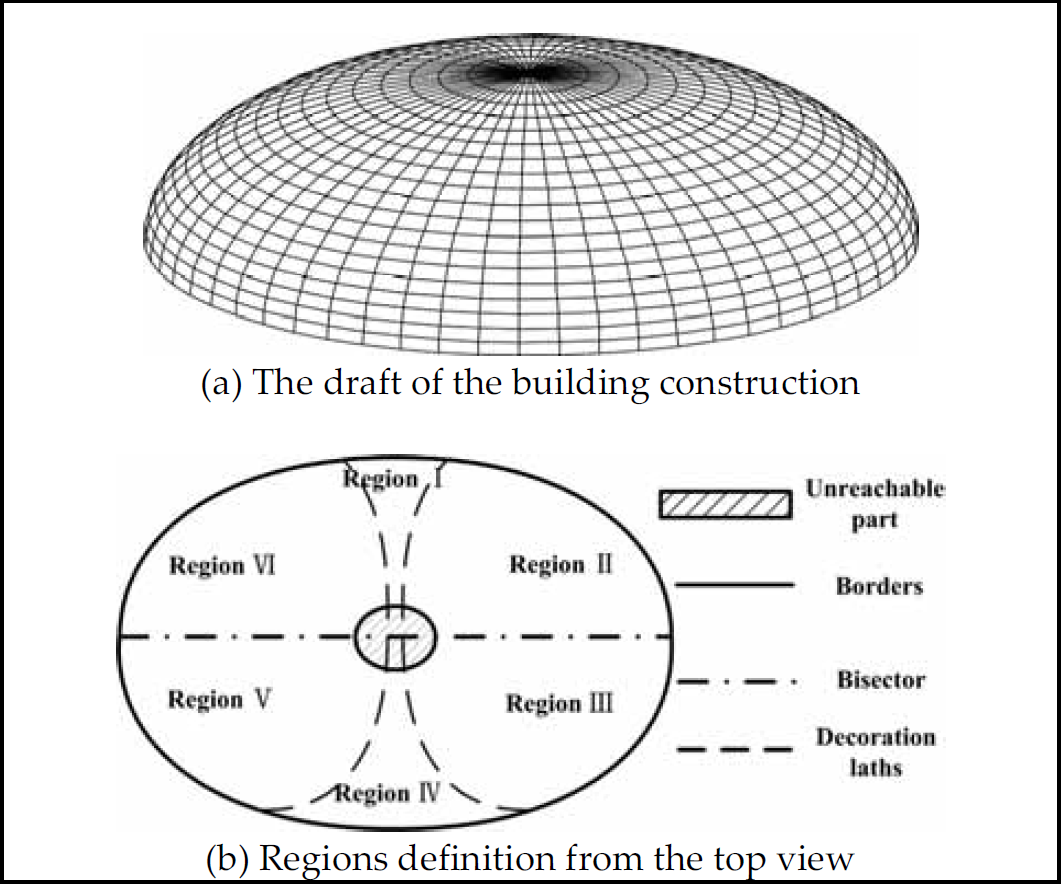
Results of subdivision
Cleaning and walking are tracked by synchronizing the global information and the local perceived situation in the phase of path planning. Firstly the robot should choose a direction along which the cleaning work can be carried out. Here a representative subdivided area on the border between Region I and Region II, as shown in Fig. 23, is the work target based on the principles of area definition. If the robot cleans the work space in the vertical direction, it has to cross the obstacles several times. It is much more difficult to clean the work target due to numerous horizontal obstacles. But the robot can clean uninhibited in the horizontal direction, because that way the wall is considered as forming a plane. The robot begins to clean the wall from the upper left point. It will move on to the next strip when the first strip of planks is finished cleaning. Some areas near the border cannot be cleaned for safety reasons. The coverage percentage on this small work area is over 95%. This value will be higher from the global point of view.

Cleaning trajectory
This paper described a kind of auto-climbing robot used for cleaning the complex curved surface of the National Grand Theatre in China. A special movement mechanism was developed and designed to satisfy weight and dexterity requirements. The robot has been tested on a demo wall which was built based on real building design. Fig. 24 and 25 show the robot climbing up and cleaning in the same process as Fig. 16, 17 respectively. The robot can climb up and down walls reliably with an average climbing speed of 200 mm/s, a sideways moving speed of 100 mm/s, and has a cleaning efficiency of 150 m2/hour. These tests have proven the feasibility of the mechanical design and control system of the robot.

Real climbing experiment

On-site cleaning experiment
The climbing and cleaning dynamics of the robot are stated by the application of the Lagrange equation. All of the results are important for system design and the design of the controlling mechanism for this climbing robot. In the end, a new cleaning trajectory was presented, which is determined and evaluated by the synthesis of work safety, cleaning efficiency and cleaning coverage percentage. Testing results with the robot have verified the effectiveness of the CCPP.