
Abstract
This paper is concerned with robotic applications using a ground-based radar sensor for simultaneous localization and mapping problems. In mobile robotics, radar technology is interesting because of its long range and the robustness of radar waves to atmospheric conditions, making these sensors well-suited for extended outdoor robotic applications. Two localization and mapping approaches using data obtained from a 360° field of view microwave radar sensor are presented and compared. The first method is a trajectory-oriented simultaneous localization and mapping technique, which makes no landmark assumptions and avoids the data association problem. The estimation of the ego-motion makes use of the Fourier-Mellin transform for registering radar images in a sequence, from which the rotation and translation of the sensor motion can be estimated. The second approach uses the consequence of using a rotating range sensor in high speed robotics. In such a situation, movement combinations create distortions in the collected data. Velocimetry is achieved here by explicitly analysing these measurement distortions. As a result, the trajectory of the vehicle and then the radar map of outdoor environments can be obtained. The evaluation of experimental results obtained by the two methods is presented on real-world data from a vehicle moving at 30 km/h over a 2.5 km course.
1. Introduction
The increased autonomy of robots is directly linked to their capability to perceive their environment. Simultaneous Localization and Mapping (SLAM) techniques, which associate perception and movement, are particularly interesting because they provide advanced autonomy to vehicles such as robots. In outdoor environments, climatic constraints or operational context (dust, light condition, rain, etc.) show the limits of usual perception systems. This work proposes radar as an alternative to existing perception systems for ground mobile robots. Its ability to work in all weather, day and night, makes the radar very attractive for outdoor applications. The combined use of radar with SLAM techniques in the field of mobile ground robotics is the main contribution of the presented work.
SLAM has been studied intensively over the past two decades. For a broad and quick review of the different approaches developed to face this high level of complexity in autonomous mobile robot applications, the reader can consult [1–4]. Localization and mapping in large outdoor environments are applications related to the availability of efficient and robust perception sensors, particularly with regard to the problem of maximum range and compliance with the environmental conditions. Even though lasers and cameras are well-suited sensors for environment perception [5–7], their strong sensitivity to atmospheric conditions has, among other reasons, given rise to an interest in the development of mapping and localization methods working with data coming from other sensors like radar or sonar [8].
In this paper, two SLAM techniques are presented using data from a 360° field of view radar sensor. This radar is based on the Frequency Modulated Continuous Wave (FMCW) technology [9]. In section 2, a review of articles related to our research work is carried out in the fields of outdoor mapping and ego-motion estimation. Section 3 briefly presents the microwave radar scanner we used and that was developed by a team from the Cemagref Institute (Irstea) working on environmental sciences and technologies. Section 4 deals with a scan-matching approach for localization and mapping. Section 5 presents an approach based on an analysis of distortion due to movement in order to extract information about the robot's trajectory and then the radar map of outdoor environments. Finally, section 6 shows experimental results.
2. Related work
2.1 Outdoor mapping
In order to perform outdoor SLAM, laser sensors have been widely used [10]. To provide localization and map building, the input range data are processed using geometric feature extraction and scan correlation techniques. Less research exists using sensors such as underwater sonar [8] and Frequency Modulated Continuous Wave (FMCW) radar. Large-area SLAM has already been carried out successfully for vision-based underwater missions over long distances [11] [12]. Interestingly, a radar sensor has already been used by Clark in [13] at the end of the last century. In an environment containing a small number of well-separated, highly reflective beacons, experiments were led with this sensor to provide a solution to the SLAM problem [2] using an extended Kalman filter framework and a landmark-based approach. In [14], a model dedicated to the radar was developed to build an occupancy grid map. Finally, in [15], a method for building a map with sensors returning both range information and received signal power information was presented. An outdoor occupancy grid map related to a 30 m vehicle's trajectory is analysed.
A common method of pose estimation for mobile robots is scan matching [16]. By solving the rigid transformation between consecutive scans from a range sensor, the robot's motion in the time period between the scans can be inferred. One of the most popular approaches for scan matching is the Iterative Closest Point (ICP) [17] algorithm. In ICP, the transformation between scans is found iteratively by assuming that every point in the first scan corresponds to its closest point in the second scan, and by calculating a closed form solution using these correspondences. However, sparse and noisy data, such as those from an imaging radar, can cause an ICP failure. A single noisy reading can significantly affect the computed transformation, causing the estimated robot pose to drift over time. Yet, it is well-known that the different possible combinations of radar signals introduce the speckle effect which can lead to ghost detections or false disappearances. To overcome this problem, the Fourier-Mellin transform for registering images in a sequence is used in our first approach [18, 19] to estimate the rotation and translation of the radar sensor motion (see section 4). In the context of scan-matching SLAM, the use of the Fourier-Mellin transform is original and provides an accurate and efficient way of computing the rigid transformation between consecutive scans (see section 6). It is a global method that takes into account the contributions of both the range and power information of the radar image. In some ways, this “global” approach is also close to the histogram correlation technique [10].
2.2 Ego-motion estimation
The estimation of a vehicle's displacement or ego-motion is a widely studied problem in mobile robotics. Most applications are based on proprioceptive data provided by odometer sensors, gyrometers, IMU or other positioning systems such as GPS [20]. But in order to estimate motion, some research works tried to use only exteroceptive data. Thus, the authors of [21–23] proposed a visual odometry without proprioceptive data. Tipaldi and Ramos [24] proposed filtering out moving objects before doing ego-motion. In such an approach, the exteroceptive ego-motion sensor is considered as augmenting rather than replacing classical proprioceptive sensors. Sometimes, classical displacement measurements are much more difficult and have limitations: inertial sensors are prone to drift, and wheel odometry is unreliable in rough terrain (wheels tend to slip and sink) and as a consequence, visual odometric approaches are widely studied [25, 26]. For example, in an underwater or naval environment, classical ego-motion techniques are not suitable. In [27], an ego-motion technique was proposed based on visual SLAM fused with IMU. In order to find displacement with exteroceptive sensors such as range finders, the scan matching method is once more commonly used [8, 28], but each scan is corrected with proprioceptive sensors, especially when the sensor is slow. In all scan matching work, distortion is taken into account but considered as a disturbance and thus corrected.
The only work dealing with distortion as a source of information used a specific camera with a rolling shutter. In [29], Ait-Aider et al. computed the instantaneous 3 D pose and velocity of fast moving objects using a single camera image, but in their context prior knowledge of the observed object is required. In mobile robotics, we have no a priori about the surrounding environment of the robot. To the best of our knowledge, there is absolutely no work in the field of mobile robotics literature considering distortion as a source of information for an odometric purpose. So, the goal of this second approach is to study and use data distortion with a mobile ground-based panoramic radar sensor in the context of field robotics and to show its usefulness for localization and mapping [30].
3. The K2Pi radar
The exploited radar uses the frequency modulation continuous wave (FMCW) technique [9]. The FMCW radar is called K2Pi (2π for panoramic - in K band) and is equipped with a rotating antenna in order to achieve a complete 360° per second monitoring around the vehicle, with an angular resolution of 3°, in the 3 – 100 m range. A general view of the radar is presented in Fig. 1 and its main characteristics are listed in Table 1. The example of two radar images is presented in Fig. 2. Variations of shading indicate variations of amplitude in the power spectra.
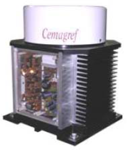
The K2Pi FMCW radar
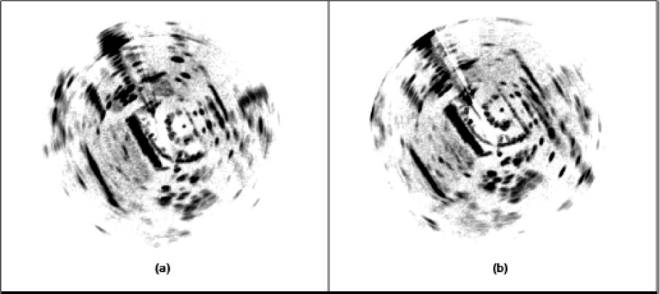
Two consecutive radar images ((a) & (b)) obtained with the FMCW radar sensor (see Fig. 1)
Characteristics of the K2Pi FMCW radar

4. FMT-R-SLAM: Fourier-Mellin transform-based radar SLAM
In order to overcome the complexity of radar image analysis, a trajectory-oriented EKF-SLAM technique using data from the 360° field of view radar sensor has been developed. This process makes no landmark assumptions and avoids the data association problem. The method of ego-motion estimation makes use of the Fourier-Mellin transform for registering radar images in a sequence, from which the rotation and translation of the sensor motion can be estimated [31]. In the context of the scan-matching SLAM, the use of the Fourier-Mellin transform is original and provides an accurate and efficient way of computing the rigid transformation between consecutive scans.
4.1 Radar scan matching SLAM
The used formulation of our SLAM approach is to estimate the vehicle trajectory defined by the estimated state

where
Scan matching is the process of translating and rotating a radar scan such that a maximal overlap with another scan emerges. Assuming the distribution of alignment errors is approximately Gaussian, a new vehicle pose is added to the SLAM map by only adding the pose to the SLAM state vector.
So, observations are associated to each pose. They are compared and registered to offer potential constraints on the global map of vehicle poses. This is not only useful for motion-based state augmentation, but it is also an essential point for loop closing.
The estimator used here is the extended Kalman filter (EKF). Given a noisy control input

The operator ⊕ is the displacement composition operator (e.g., [32]).

where the operator ⊖ is the inverse transformation operator.
Observations are assumed to be made according to a model of the form:

in which
4.2 Fourier-Mellin transform for ego-motion estimation
The problem of registering two scans in order to determine their relative positions has to be solved. The choice of an algorithm is strongly influenced by the need for real-time operation. A FFT-based algorithm was chosen to perform scan matching.
Fourier-based schemes are able to estimate large rotations, scalings and translations. Let us note that the scale factor is irrelevant in our case. Most of the DFT-based approaches use the shift property [31] of the Fourier transform, which enables robust estimation of translations using normalized phase correlation.
To match two scans which are translated and rotated with respect to each other, the phase correlation method is used, stating that a shift in the coordinate frames of two functions is transformed in the Fourier domain as a linear phase difference. To deal with the rotation as a translational displacement, the images are previously transformed into a uniform polar Fourier representation.
It is known that if two images
Hence, the normalized cross power spectrum is given by

Taking the inverse Fourier transform:

which means that Corr(x,y) is non-zero only at (Δx,Δy) = arg max(x,y) {Corr(x,y)}. If the two images differ by rotational movement (θ0) with translation (Δx,Δy), then

Converting from rectangular coordinates to polar coordinates makes it possible to represent rotation as shift: the Fourier transform in polar coordinates is

Introducing the magnitudes of

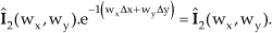
The shift between the two images can now be resolved using (1).
4.3 Scan registration
In order to perform a scan registration algorithm, the Fourier-Mellin transform (FMT) has been chosen [34] [31]. The FMT is a global method that takes the contributions from all points in the images into account, in order to provide a way to recover all rigid transformation parameters, i.e., rotation, translation. It is an efficient and accurate method to process a couple of images that are fairly similar (see Fig. 2). The steps of the scan registration algorithm are presented in Algorithm 1.
Apply the thresholding filter to eliminate the speckle noise in both images Apply the FFT to images Compute the magnitudes | Transform the resulting values from rectangular to polar coordinates. Apply the FFT to polar images, a bilinear interpolation is used. Compute Compute Find the location of the maximum of Construct Apply the FFT to image Compute the correlation Take the inverse FFT Corr(x,y) of
5. ROLAM: Radar-only localization and mapping
In a robotics context, it is usually assumed that the scan of a range sensor is a collection of depth measurements taken from a single robot position. This can be done when working with lasers that are much faster than radar sensors and can be considered instantaneous when compared with the dynamics of the vehicle. However, when the robot is moving at high speed, most of the time, this assumption is unacceptable. Important distortion phenomena appear and cannot be ignored. In the case of a laser range finder with a 75 Hz scanning rate, distortion exists but is ignored. This assumption is valid for low speed applications, nevertheless still moving straight ahead at a speed of 5 m/s, a 7 cm distortion effect appears. At classical road vehicle speeds (in cities, on roads or motorways) more important distortions can be observed. Of course, the rotation of the vehicle itself during the measurement acquisition is another source of disturbance which cannot be neglected for high speed displacement or with slow sensors (cf. Fig. 3). Finally, let us note that when the sensor is too slow, a “stop & scan” method is often applied [35].

Distorted data from a real sensor: radar data (a) with distortion effect (b) without any distortion effect
For example, in the previous radar mapping application (presented in section 4), the sensor delivers one panoramic radar image per second. When the robot keeps moving straight ahead, at a low speed of 5 m/s, the panoramic image includes a 5-metre distortion. We deal with this distortion by using proprioceptive sensors in order to estimate the trajectory and to build a virtual scan taken from a single position. In fact, distortion is considered as a noise and filtered out. In our second approach, we use distortion as a source of information regarding the displacement of the vehicle. The objective here is not to remove distortion but to extract movement information from it.
5.1 Distortion problem statement
Distortion is the alteration of the data as also observed in our radar images (cf. Fig. 3). With a rotating range sensor, the desired acquisition should represent the surroundings of the robot at time t. When the sensor's rotation speed is slow compared to the vehicle's motion, the changes in the robot's location during the acquisition period lead to image distortion. This distortion effect is presented on real and simulated data in Fig. 3 & 4.

(a) Distortion phenomenon: when the vehicle is moving along the green trajectory, the sensor is scanning. The sensor beams are represented in red and blue during the first and second radar acquisition respectively. The first and the last beam of each acquisition do not measure the same thing. Each scan is distorted by movement. (b) represents the desired acquisition from the second position (or in case of stop & scan method) with corrected beam
Without any prior knowledge of the environment, a unique scan acquisition from a single sensor cannot give information about distortion. This is one of the reasons why distortion is usually considered as noise and corrected by proprioceptive sensors. The aim of this second approach is to measure the distortion of the data by comparing successive radar images in order to extract information about the robot's movement. By using a rotating sensor without any knowledge of the environment shape, two successive observations are required. The stated assumption is the local constant velocity of the vehicle during two successive measurements. The pose of each measurement is directly linked to the observation pose and to the angle of observation. This pose can be expressed with the constant velocity model of the vehicle and is only a function of the linear and angular speed of the robot.
Data distortion results from combined sensor and vehicle movements. The distortion equation can be represented by the parametric equation of a trochoid as shown in Fig. 4 (a). Indeed, at time t, the position of a detection done at range pis a function of the centre
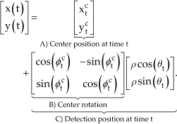
In order to obtain the centre pose at timet, an evolution model taking into account the linear (V) and angular (ω) velocities is formulated. Pose

If based on this distortion parametric equation, the measurements can be distorted or undistorted. The equation is parameterized with respect to the linear and angular velocities V and ω. With a prior estimate of these parameters, detection (θ,ρ), done at time tin the sensor frame, can be transformed into the world frame based on (3) and (2) (cf. Fig. 5).

(a) Data obtained in sensor frame without considering distortion. (b) Undistorted data based on distortion formulation
The objective is to estimate proprioceptive information, in fact velocities V and ω, which best undistort the measurements.
5.2 Proprioceptive information extraction
According to the assumption that the velocity of the vehicle is locally constant during two successive measurements, the effective velocities of the robot will be those that, using distortion formulation, allow superimposing detections of the same object in the world.
The pose of each measurement is directly linked to the observation pose and to the angle of observation. This pose can be expressed with the constant velocity model of the vehicle and is only a function of the linear and angular speeds of the robot, see (3). Let

Principle of distortion analysis: the detected landmark in each scan in red, and the corresponding landmark in the real world; the predicted detection pose from scan 1 onto scan 2 in green
Because the radar data are submitted to different perturbations (such as speckle, Doppler, antenna aperture, etc.) the appearance of a detected object keeps changing from one scan to another. As a consequence, no descriptor is available to perform data association, so it is based only on the Mahalanobis distance between predictions and measurements. The function h = g–1 ○ f is unknown because g–1 cannot be obtained; consequently, minimization techniques have to be used in order to estimate
The robot moves from an initial pose

where λ is the wavelength of the radar signal, α a coefficient which links frequency and distance, and ωsensor the rotating rate of the sensor. If no Doppler effect has to be considered, as is the case with laser sensors, simply note that
So,

For the first radar image, the function f can be expressed as:

Similarly, for the second
The entire set of detections in the world frame can be easily expressed in a matricial form based on (6). Based on these equations we can conclude that distortion is linked to the velocity parameters (V,ω), to the landmarks in the two successive scans
5.3 Estimation of velocities
In order to estimate the velocity parameters (V,ω)T, the data association between landmarks from the two successive scans needs to be done.

A gradient method with adaptive step-sizes is used to minimize this cost function. As a result, the prediction of the first radar image landmarks can be computed in the second image as well as its uncertainty ellipsis. Data association between prediction
As radar data are very noisy (cf. Fig. 2), both landmark extraction and data association can be false. For example, the speckle effect can lead to some ghost detections or false disappearances due to the different possible combinations of radar signals. Moreover, due to multiple reflections, radar data are not as accurate as laser data. Thus, all possible data associations have to be considered.
Two assumptions are made at this point. First, the percentage of detections due to static objects has to be sufficient. Indeed detections coming from moving objects can lead to false velocity estimates. Moreover, if all the detections coming from moving objects are coherent and give the same velocity estimate, the most pessimistic requirement is that 50% of the detections in the environment have to come from static objects.
Second, the vehicle equipped with the radar sensor is supposed to be moving during two consecutive acquisitions at a constant velocity (V and ω). Actually, when the vehicle accelerates or decelerates, the estimated velocity obtained will be the mean speed of the vehicle.
For each data association allowed by the Mahalanobis distance, a new estimate of the robot's velocity is computed and sent over to an extended Kalman filter process. Then, updated speeds are projected into the velocity space with their respective uncertainties. In this space, the global coherence of the scene is achieved by fusing all the consistent estimates. This fusion process is done after removing the outliers (i.e., wrong detections and associations) using a RANSAC process. Indeed, we suppose that most detections are static and well associated. The fusion uses the covariance intersection (CI) [36] method in order to be more pessimistic in the case of the presence of any residual wrong vote during fusion.
6. Experimental results
This section provides the experimental results of both radar-based approaches. The radar and the proprioceptive sensors were mounted on a utility car. The experimental run that is presented was conducted in an outdoor field, around the Auvergne Zenith car park (cf. aerial view in Fig. 9(a)), with a semi-structured environment (buildings, trees, roads, road signs, etc.). The K2Pi radar was on top of the vehicle, two metres above the ground. A 2.5 km trajectory was travelled at a mean speed of 30 km/h. In order to evaluate the performance assessment of each approach, a DGPS system was used to provide a reference trajectory. Radar images as well as the data obtained from the other sensors were recorded and post-processed as explained previously.

Trajectories obtained by the two methods. In black the DGPS reference trajectory, in red (dot-dashed curve) the trajectory obtained by the FMT-R-SLAM approach and in blue (star-dashed curve) the ROLAM trajectory

Translational transformation norm and estimation of rotation for both approaches. (a) Norm of the translational displacement at each step, (b) norm of the translational displacement error. (c) Value of rotation at each step, (d) error in rotation

(a) Aerial Google view. (b) Radar map obtained by the FMT-R-SLAM process. (c) Radar map obtained by the ROLAM process
The trajectories obtained by the FMT-R-SLAM and ROLAM algorithms are presented, respectively in red (dot-dashed curve) and blue (star-dashed curve), in Fig. 7 and the reference trajectory is plotted in black. Due to the fact that, without a loop closure, the error is cumulated all along the trajectory, the positioning error is growing and represents the drift of the process.
In order to obtain an efficient and correct evaluation of the results, relative displacements between robot poses are studied. Figure 8(a) represents the translational transformation value for the two approaches and the reference. Figure 8(b) is the corresponding estimation error. As a result of the initial acceleration, a peak at the beginning of the translational transformation error plot can be observed for the ROLAM approach. This effect is not so obvious with the FMT-R-SLAM method. The angular comparison is described in Fig. 8(a)&(b). It may be observed that at the given times 90 s and 135 s, peaks appear in the estimation of the rotation angle (and, to a lesser extent, in translation). This error is due to driving around the roundabouts at high speed, thus making the assumption of constant angular velocity erroneous; as a consequence, the estimates of angular velocity are not as good as expected at this particular stage.
In order to compare both results in a quantitative way, different criteria have been considered. First, the global positioning error, directly linked to the visual evaluation of the trajectory, is analysed. The cumulative error of the dead reckoning method makes the final error with respect to the ground truth trajectory equal to 65 and 48 metres with respectively FMT-R-SLAM and ROLAM algorithms after a trajectory of 2.5 km. Due to the fact this metric takes into account the cumulative errors which do not represent directly the quality of the estimates, two metrics based on relative displacement are considered. Successive translational and rotational transformations are estimated. All quantitative results are summarized in Table 2.
Trajectory evaluation

The FMT-R-SLAM approach provides displacement results with a mean error of –0.09 m and a standard deviation of 0.38 m, while the ROLAM algorithm has a mean error of –0.20 m with a 0.70 m standard deviation. Considering rotation, the FMT-R-SLAM algorithm obtains a mean error of –0.03 deg with a standard deviation of 0.1 deg, while the ROLAM process gives a zero mean error with a 0.15 deg standard deviation.
By analysing these values, we can conclude that both the FMT-R-SLAM and ROLAM algorithms allow obtaining a good estimate of the vehicle trajectory, even if the FMT-R-SLAM approach seems to provide more accurate displacement estimates while the ROLAM technique gives better results in rotation. Both methods produce interesting trajectory results which allow building a radar map by positioning each radar scan at its corresponding estimated position. A radar-mapping result based on the FMT-R-SLAM process is given in Fig. 9(b). As illustrated in Fig 9(c), a map can also be obtained by the ROLAM algorithm if the acquisition poses of each beam, that have been predicted, are recorded. In this case, each raw radar spectrum is positioned and plotted in order to build a map. In both cases, the maps reveal details of the environment, but a difference appears due to the fact that no filtering is applied in the second approach. Of course, post-processing could have been added in order to remove these different perturbations (speckle effect, Doppler, antenna aperture, etc.) and to improve the appearance of the map. We chose to present the results in this manner in order to highlight the difference between both approaches: the first one is based on a scan-matching technique, the second one deals with each radar beam as previously explained.
Considering time processing, the pose estimation with Matlab is done by ROLAM in an average processing time of 26 ms with an average number of 10 considered landmarks. One step of the FMT-R-SLAM process (scan building, scan registration, prediction and update), implemented in C/C++, is achieved in less than one second with a QuadCore Intel Xeon (2.8 GHz) with six Go DDR2 FB-DIMM RAM (667 MHz). The processing time increases when trying to manage how to “close the loop”, but this case is not considered here. The radar frequency being 1 Hz, both approaches can be implemented in real time.
7. Conclusion
Two methods for computing a mobile robot's localization estimates in natural or semi-natural environments are presented using radar technology. By using such a ground-based microwave radar sensor, which is most unusual in mobile robotics, a trajectory-oriented SLAM process is first proposed. It is based on the Fourier-Mellin transform and the extended Kalman filter. The second approach presented is based on the fact that when the robot moves at high speed while the sensor is rotating, data are subject to distortion phenomena. This second method computes the velocimetry of the vehicle by explicitly analysing these measurement distortions. Such radar-based odometry does not use any proprioceptive sensors. This part of the presented work can be extended to any kind of non-instantaneous rotating sensor. Our two approaches work without any knowledge of the vehicle's surroundings; not only do they allow estimating the robot's trajectory, they also permit building a map of the environment. An evaluation and a comparative study of the two proposed methods on real-world data over a 2.5 km course have been conducted, which have demonstrated their feasibility and reliability for mobile ground vehicles at high speed (30 km/h).
Footnotes
8. Acknowledgements
This study was supported by the Agence Nationale de la Recherche (ANR—the French National Research Agency) (ANR Impala PsiRob—ANR-06-ROBO-0012). The authors would like to thank the members of Cemagref (Irstea) for their kind loan of the radar sensor used in this paper. This work has also been funded by the French government research programme Investissements d'avenir through the RobotEx Equipment of Excellence (ANR-10- EQPX-44) and the IMobS3 Laboratory of Excellence (ANR-10-LABX-16-01), by the European Union through the programme Regional Competitiveness and Employment 2007-2013 (ERDF - Auvergne region), by the Auvergne region and by the French Institute for Advanced Mechanics.