
Abstract
This paper presents the design and implementation of a hand-held interface system for the locomotion control of home robots. A handheld controller is proposed to implement hand motion recognition and hand motion-based robot control. The handheld controller can provide a ‘connect-and-play’ service for the users to control the home robot with visual and vibrotactile feedback. Six natural hand gestures are defined for navigating the home robots. A three-axis accelerometer is used to detect the hand motions of the user. The recorded acceleration data are analysed and classified to corresponding control commands according to their characteristic curves. A vibration motor is used to provide vibrotactile feedback to the user when an improper operation is performed. The performances of the proposed hand motion-based interface and the traditional keyboard and mouse interface have been compared in robot navigation experiments. The experimental results of home robot navigation show that the success rate of the handheld controller is 13.33% higher than the PC based controller. The precision of the handheld controller is 15.4% more than that of the PC and the execution time is 24.7% less than the PC based controller. This means that the proposed hand motion-based interface is more efficient and flexible.
1. Introduction
In recent years, more and more mobile robots have moved away from industry to enter home environments. As the size and the cost have decreased significantly, the home robot is now available for use as one of the most popular consumer electronic products [1]. More and more home robots are now working around us and they help us a lot in our daily lives. A wide variety of home robots have been proposed to do housework such as cooking, cleaning, houseplant watering and pet feeding. They are also being widely used in home security, entertainment, rehabilitation training and home care for the elderly [2–5].
As the home robots get closer in our daily lives, the question arises: How to interact with them? Complicated control interfaces designed for skilled workers and experts are not suitable for ordinary home users. They prefer simple and natural interaction with home robots through voices and gestures. This requires a user-friendly interface that allows the robot to understand voice and gesture commands. The voice interface is suitable for a simple call-and-come service for home robots [6] but it is not suitable for continuous remote control and usually it cannot work normally due to the interference of ambient noise. Therefore, hand gesture or hand motion-based interfaces are more suitable for control of home robots.
Several methods have been proposed for hand gesture recognition, such as marker-based gesture recognition, vision-based motion recognition, haptic-based motion recognition and EMG-based hand motion recognition [7]. In [8], a real-time hand gesture recognition system based on difference image entropy using a stereo camera is introduced. The proposed method shows an average recognition rate of 85%. Other hand gesture recognition methods use wearable sensors, accelerometers, angular rate sensors and data gloves to detect hand gestures. In [9], a data glove is used for 3D hand motion tracking and gesture recognition. In [10], the authors proposed a set of recognition algorithms: TC, FAcaGMM and FEC. They evaluated the algorithms on a data glove with 13 different types of grasps and ten in-hand manipulations. In [11–12], the authors used a wearable sensor to recognize hand gestures and daily activities in a smart assisted living system to help elderly people, patients and the disabled. In [13], a wearable wristwatch-type controller is introduced to offer a unified way to control various devices. The controller uses simple and effective hand motion gestures for controlling devices. In [14], an accelerometer combined with a visual tracker is used to detect hand movements in a system for human computer interaction.
As compared to the wearable sensor-based control interface, the handheld interface is more suitable for controlling home robots. Since people are used to this kind of control mode they can learn to use it quickly and easily. Wearable sensors fixed on the body of a person are not convenient and flexible to use when he or she wants to control a robot. In [15], the authors introduce a handheld interface system for 3D interaction with digital media contents. The system can track the full six degrees-of-freedom position and orientation of a handheld controller. The gesture recognition depends on acceleration and position measurements. A hand-gesture-based control interface for navigating a car robot is introduced in [16]. A three-axis accelerometer is adopted to record the hand trajectories of a user. In [17–18], the authors proposed a handheld system to recognize hand motions. The system contains three MEMS accelerometers and a Bluetooth wireless module.
Hand gestures usually can be described by the tilt angles of the hand. So tilt sensors can be used to detect the angles of a hand gesture. In [19], a tilt sensor was designed using standard accelerometers. The accuracy of the tilt sensor is 0.3° over the full measurement range of pitch and roll. In [20], the authors used a Kalman filter to estimate inclination from the signals of a three-axis accelerometer for measuring inclination of body segments and activity of daily living (ADL). This method is nearly twice as accurate as the methods based on low-pass filtering of accelerometer signals. In [21], a three-axis accelerometer and a dual-axis angular rate sensor are utilized for orientation sensing in mobile virtual environments. It presents a technical and theoretical description for implementing an orientation-aware device, which is used for navigating large images spread out on a virtual hemispheric space in front of the user through a mobile display. In [22], a novel approach for hand gesture recognition is introduced. In [23], a hand gesture recognition system is implemented to detect hand gestures in any orientation. The system is integrated on an interactive robot, allowing for real-time hand gesture interaction with the robot. Gestures are translated into goals for the robot, telling him where to go.
Vibration motors are usually used in handheld interfaces to provide vibrotactile feedback. In [15], a vibration motor and a voice-coil actuator are adopted to achieve vibrotactile feedback. In [24], vibrotactile actuators are used in a handheld input device for providing spatial and directional information. In [25], a vibrotactile feedback approach for posture guidance is introduced and in [26], multi-day training with vibrotactile feedback for virtual object manipulation is introduced. Experimental results show that participants are able to utilize the vibrotactile feedback to improve the performance of virtual object manipulation.
In this paper, we present a hand motion-based remote control interface with vibrotactile feedback for home robots. A handheld controller is proposed to implement hand motion recognition and hand motion-based robot control. The handheld controller can provide a ‘connect-and-play’ service for the users to control the home robot. Meanwhile, it implements the function of visual and vibrotactile feedback. Six simple hand gestures are defined for locomotion control of the robot. They are easy to use for untrained people. A three-axis accelerometer is used to detect the hand motions of the user. The recorded acceleration data are analysed and classified to corresponding control commands according to their characteristic curves. A vibration motor is used to provide vibrotactile feedback to the user when an improper operation is performed.
The remainder of this paper is organized as follows. Section 2 introduces the overall system architecture that includes the handheld controller and the home robot. The hardware design of the handheld controller is presented in Section 3. The methods of hand motion recognition and hand motion-based robot control are presented in Section 4. The experimental results on the performance of the prototype system are given in Section 5. Concluding remarks are given in Section 4.
2. System description
The conceptual architecture of the hand motion based control system is shown in Figure 1.
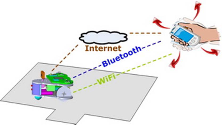
Conceptual system architecture. The user controls the robot by rotating the handheld controller. The hand motions are recognized by the handheld controller and converted to motion commands.
The system consists of a handheld controller and a home surveillance robot. The handheld controller has a three-axis accelerometer and a vibration motor for user interaction. It can sense the accelerations of the hand motions of the user and convert those acceleration values to robot control commands. The commands are sent to the robot to implement various motion control applications. There are three alternative schemas for establishing wireless communication links between the handheld controller and the robot, i.e., Wi-Fi, Bluetooth and TCP/IP. The home surveillance robot used in our system is shown in Figure 2. It is a palm-sized mobile robot with an on-board camera for home security applications. The detailed design work of this robot has been presented in [5].

The home surveillance robot.
The software structure of the control system is shown in Figure 3. The embedded programs in the handheld controller include a hand motion recognizer, a graphical user interface (GUI) and a vibrotactile feedback generator. The embedded program in the robot can implement basic locomotion behaviours and other high-level behaviours such as video transmission, cruising, docking and recharging. The obstacle information and the current status of the robot are also useful when no wall-mounted or ceiling-mounted cameras are available.

Software structure of the hand motion-based control system.
3. Handheld controller
A prototype of the handheld controller is shown in Figure 5. The size of the controller is 137mm×90mm×31mm and its weight is about 250g. The handheld controller is portable equipment designed for controlling home robots by hand motions. It includes a core board, a microcontroller unit (MCU), a three-axis accelerometer, a Wi-Fi adapter, a touch screen, two USB ports and a vibration motor, as shown in Figure 4.

Hardware structure of the handheld controller.
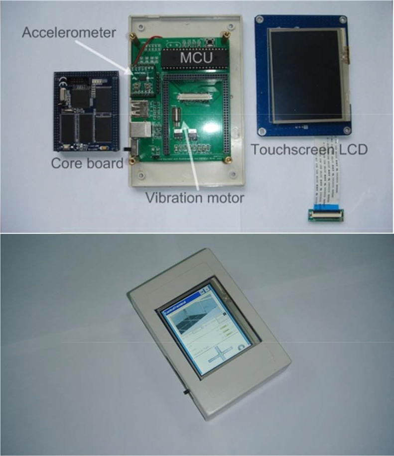
Implemented prototype of the handheld controller. The size of the handheld controller is 137mm×90mm×31mm (L×W×H). Its weight is 252g.
The core board is a small embedded computer system that provides most of the communication interfaces needed here. A standalone MCU is adopted for acceleration acquisition and processing in order to ensure good real-time performance. It communicates with the core board through a serial port. Users can access the Internet via the Wi-Fi adapter for remote robot controlling. Therefore, the controller can provide the ‘connect-and-play’ service for the users. And it can provide sufficient bandwidth for video transmission. A touchscreen LCD module is used to give necessary visual feedback for the users to implement remote control. It also allows touch input for the users to manage and configure the control system.
4. Hand motion-based control
4.1 Coordinate System
The first step to implementing hand motion recognition by the handheld controller is the definition of reference frames. The three-dimensional Cartesian coordinate system of the handheld controller is shown in Figure 6. The three-axis accelerometer is assumed to be fixed to the origin of the coordinate system and its sensing axes coincide with the axes depicted in Figure 6. The positive direction of the Z-axis is defined as the direction going vertically out from the screen of the device. The positive direction of the X-axis is defined as the direction to the right side when a user holds the device and sees the screen. Then, the positive direction of the Y-axis will be the front direction in which the device is pointing.
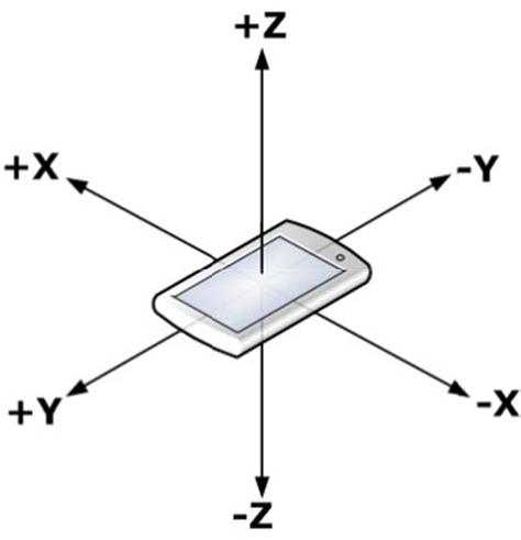
3-dimensional coordinate system of the handheld controller.
4.2 Hand Motion Recognition
The handheld controller is a 3D rigid body that can be rotated about the three orthogonal axes. According to aviation terminology, these rotations will be referred to as yaw, pitch and roll. The orientation of the rigid body is often represented by using Euler angles that are composed of those three elemental rotation angles. The first rotation about the Z-axis is called yaw, the next rotation about the X-axis of is called pitch and the last rotation about the Y-axis is called roll. Any orientation can be achieved by composing those three elemental rotations.
In our work, all of the planned hand motions for robot control are simple gestures, each of which contains only one of the three elemental rotations. Gestures composed of more than one elemental rotation are too complicated for this kind of application. The real-time control performance is not acceptable when too many complicated gestures are used. It will also be too difficult for the user to learn and use. So we directly use the three measured acceleration values to describe the rotation of the handheld controller.
We have designed six simple hand motions for home robot navigation and control, as shown in Figure 7. The hand motion patterns are all commonly used in daily life. A user can easily repeat all these actions well without any special training. There is a significant difference between any two of the hand motion patterns, so it is easy for the handheld controller to accurately distinguish among different hand motion patterns. Then we can translate these hand motions to corresponding robot control commands. This kind of user interface design allows us to ensure that a user-independent and user-friendly control system is implemented.

Hand motion set for controlling the home robot. The controller is in the right hand of the user in this example. R (L) represents the command to turn the robot right (left) when the user tilts the controller to the right (left). F (B) represents the command to move the robot forward (backward) when the user tilts the controller forward (backward). U represents the command to make a U-turn when the user tilts the controller 180° to the right. S represents the command to stop when the user tilts the controller 180° to the left.
R (L) represents the command to turn the robot right (left) when the user tilts the controller to the right (left). F (B) represents the command to move the robot forward (backward) when the user tilts the controller forward (backward). U represents the command to make a U-turn when the user tilts the controller 180° to the right with the back of the controller facing up. S represents the command to stop when the user tilts the controller 180° to the left with the back of the controller facing up.
The handheld controller continuously recognizes the six hand motions by analysing the acceleration values of the integrated accelerometer. The accelerations in the three axes change simultaneously during the hand motions, but for any proposed hand motion, the acceleration in one axis will change little while that in the other two axes will change significantly as compared to the previous one, because all the proposed hand motions are designed to be either a single roll rotation or a single pitch rotation. Based on this principle, we can get the unique acceleration characteristics of every hand motion and therefore identify different hand motions.
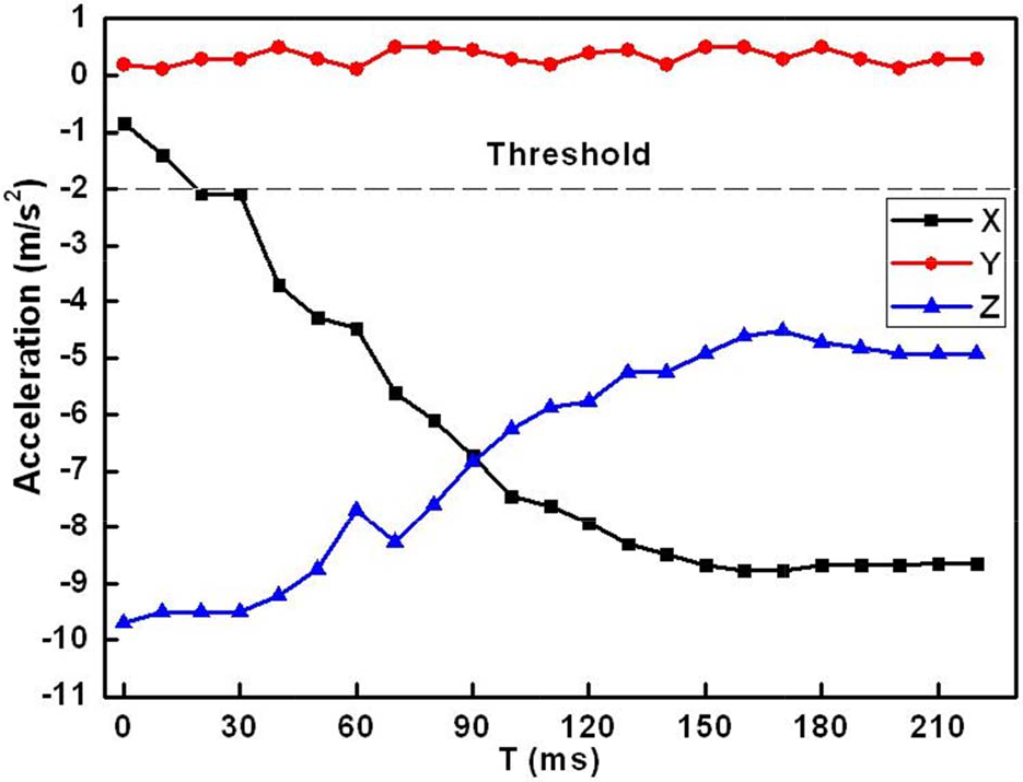
The six hand motion trials, which are shown in Figure 7, have been carried out to gather typical acceleration data to assess the acceleration characteristics of different hand motions. Example plots of the acceleration changes during the hand motions are shown in Figures 8–13. The directions of the hand motions are reflected by the variation trends of accelerations in the three axes.

Acceleration characteristics of the R motion.
Acceleration characteristics of the L motion.

Acceleration characteristics of the F motion.

Acceleration characteristics of the B motion.

Acceleration characteristics of the U motion.

Acceleration characteristics of the S motion.
The hand motions can be divided into two groups. One group is where the handheld controller is revolved by the X-axis, while the other one is where the controller is revolved around the Y-axis. The acceleration of the rotation axis almost remains within a threshold range [-2m/s2, +2m/s2]. Therefore, the first step of the hand motion recognition is to find the axis around which the handheld controller is revolved. For example, as shown in Figure 8 and Figure 9, the Y-axis acceleration remains almost unchanged during the R/L roll motion while the X-axis and the Z-axis accelerations increase or decrease significantly.
The second step is to compare the variation trends of the other two axes to determine which the hand motions are. The variation trends of the six hand motions are shown in Table 1. The algorithm of the variation trends recognition is presented in Figure 14. The values of the accelerations of each axis are sampled with a fixed 10ms interval. Each hand motion is detected with a 1.5s time span. We can get a 150 acceleration data sequence for each hand motion. The data from the acceleration sensor firstly need to pass the moving-average filter to make the data curve change smoothly. By comparing the two continuous values, Sample_NEW and Sample_OLD, MAX(i) and MIN(j) (i, j are their positions in the sequence respectively) can be obtained and the variation trends can be examined. Finally, we can obtain the styles of hand motion, robot speed and target distance/angle, which are needed for the robot control commands.
Hand motion characteristics for controlling the home robot. ‘↗’ represents that the N-axis (N = X or Y) acceleration increases monotonically. ‘↘’ represents decreasing monotonically. ‘↗, ↘’ represents increasing at first and decreasing later. ‘↗, ↘’ is opposite to ‘↘,↗’


The process of the variation trends recognized. The Motion represents the hand motion type. The Speed is used to control the robot speed. D/A represents the distance or angle which the robot needs to adjust.
4.3 Robot Control Commands
Once one of the hand motions shown in Figure 7 is identified, it will be converted to the corresponding robot control command by the control algorithm running in the controller. This process of the control algorithm is shown in Figure15. If the controller does not receive the error feedback from the robot, a new hand motion will be detected. Then the controller will identify whether the hand motion is correct or not. If the hand motion is recognized correctly, it will be mapped into the robot control command. All operating status messages will be updated on the GUI. The users also can get feedback from the vibration motor.

Control algorithm of the handheld controller.
The seven-byte command packet contains the Header, Length, Motion, Distance/Angle, Speed, Tail and CRC fields. The Header, Length and Tail fields are predefined. The Motion field is consistent with the hand motions. The Distance/Angle field is decided by tilt angle of the handheld controller. The Speed field is determined by the velocity of the hand motions. The CRC field will ensure whether the commands are error decoding or not. The details of the mapping relation are listed in Table 2.
The mapping between hand motion and robot control commands.

4.4 Graphical User Interface
A graphical user interface (GUI) is not needed for the hand motion based control system when the robot works locally and stays in sight. However, in most cases the robot is in a remote site and cannot be seen by the user with only his or her naked eyes. Therefore, a GUI has to be designed to provide necessary visual feedback for the users to implement remote control. The GUI of the handheld controller is shown in Figure 16. A cross-shaped virtual track is used to display the current pose of the handheld controller. Therefore the user will immediately know what command is sent to the robot. For example, if the user tilts the controller to the right to perform a standard R motion, the right branch of the track will light up to remind the user that an R motion is generated. If the circle in the centre of the track gives out light, it indicates that the handheld controller is in its default level posture with no motion commands generated. However, we do not suggest using this method to stop the robot since this level of posture is hard to reach and hold by the user.

Graphic user interface of the handheld controller.
4.5 Vibrotactile Feedback Generator
A vibration motor is used to alert the user with vibrotactile feedback when an improper operation is performed. As shown in Figure 15, there are many operating statuses that need to be fed back to the users. The vibrotactile feedback generator will determine the vibration signals based on the statuses. The vibrotactile feedback varies in vibration frequencies and vibration counts. The frequency of its sinusoidal vibration can be altered by changing the voltage level applied to the motor. The characteristics of vibration motor output are shown in Figure 17.

Characteristics of vibration motor output.
5. Experiments
Some experiments have been carried out to evaluate the performance of the proposed hand motion-based control system. The robot command execution rate, the hand motion recognition rate of the handheld controller and the performance of the hand motion based control interface in the robot navigation applications have been investigated.
5.1 Robot Commands Execution
The control flexibility of the proposed hand motion-based control interface is directly influenced by the response sensitivity of the robot. If the control interface generates and sends the control commands to the robot too fast, the robot will not be able to process and execute every command in time. Some commands will be discarded, which will cause the control process to be unsmooth and unstable. If the control interface generates and sends the control commands to the robot too slowly, the user will become aware of the pause and delay. The control efficiency will then be unacceptable.
The response sensitivity of the robot can be quantified by its command execution rate (CER). The CER will change when we adjust the command detection interval (CDI) of the control interface. For most of the control applications, a CER of 100% is needed. Therefore, we have carried characterization tests to determine the shortest CDI to enable a CER of 100%. Five tests with different CDIs have been done. 30 control commands are sent to the robot in each test. The test results are shown in Figure 18. It is clear that when the CDI is less than 100ms, the CER increases with the CDI. When the CDI equals 100ms, the CER is 97%. If the CDI increases again, the CER remains almost unchanged. With consideration of the real-time control, the CDI of 100ms is chosen for our control system.

Command execution rate (CER) changes with the command detection interval (CDI).
5.2 Hand Motions Recognition
Several factors can affect the results of hand motion recognition. Firstly, all the 3D hand motions are made in free space so that it is impossible to define a fixed trajectory for any motion type. Secondly, the same hand motion will be made differently each time due to individual user differences. Even for the same person, the same hand motion will be made with different range and speed each time.
Therefore we selected five subjects to participate in the hand motion recognition tests without special training beforehand. Each person was asked to repeat the same hand motion 20 times, so each hand motion was tested for 100 times. Finally, 600 test results of the six hand motions were recorded in the database, as shown in Table 3. Both the single hand motion recognition rate and the average recognition rate are calculated. The average recognition rate of six hand motions is 88.5%.
Recognition results of the hand motions.

5.3 Performance of Handheld Controller
In order to test the performance of the handheld controller in the robot navigation applications, a testbed was built in our laboratory. The testbed setup is shown in Figure 19. The side length of each white square on the testbed surface is 30cm. The home robot is ordered to complete the navigation task by following the pink lines in the figure, which is from position A to position B. The users are asked to use the handheld controller and a PC to remotely control the robot respectively. Both the handheld controller and the PC run the same high-level control program. But the control program on the PC only allows the users to use the traditional keyboard and mouse interface, which only has several basic buttons to control the robot. The handheld controller, the PC and the home robot connect to a wireless local area network router through Wi-Fi.
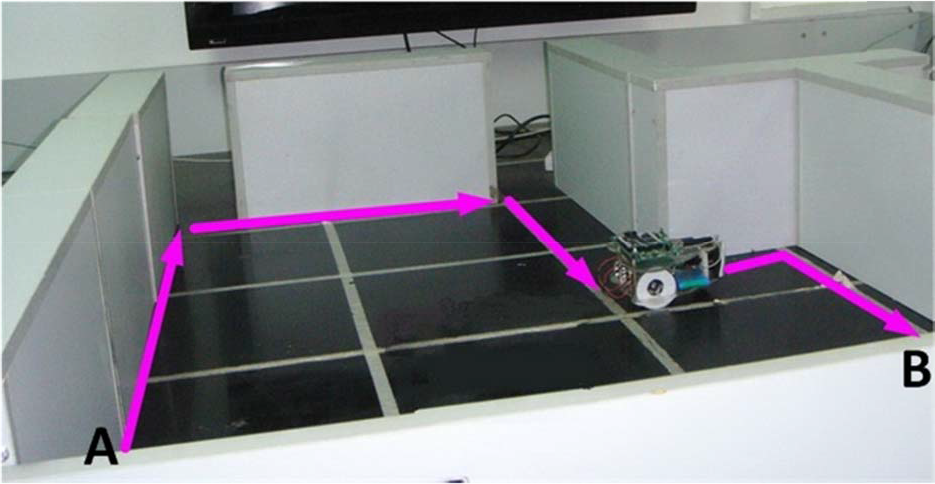
Test bed setup for the robot navigation tests.
The navigation test is repeated 15 times for each type of control interface. The test is considered to be successful if the deviation between the actual destination and the ideal destination is less than 10cm. The destination deviations of the successful tests are shown in Figure 20. The navigation attempt by the handheld controller succeeds 14 times, while the navigation attempt by the PC succeeds 12 times. The success rate of navigation attempts by the handheld controller is 93.33%. Meanwhile, the success rate of the PC control is only 80%. The precision of the handheld controller is 15.4% more than that of the PC. The execution times of the navigation tests are shown in Figure 21. The average time to complete the navigation task by the handheld controller is 24.7% less than that by the PC.
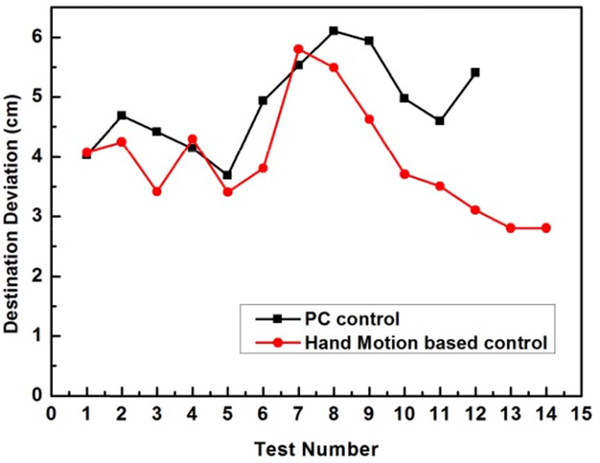
Destination deviations of the navigation tests.

Execution times of the navigation tests.
6. Conclusion
We have presented the design and implementation of a hand motion-based interface system for locomotion control of home robots. A handheld controller with a 3-axis accelerometer and a vibration motor is proposed to implement hand motion recognition and hand motion-based robot control. The handheld controller can provide the ‘connect-and-play’ service for the users to control the home robot. Meanwhile, it implements the function of visual and vibrotactile feedback. Six simple and natural hand gestures are defined for navigating the home robots. They are easily used by people without special training. Different hand motions are identified by analysing and comparing the recorded acceleration data with the unique acceleration characteristics of every hand motion. The hand motion recognition test results show that the proposed handheld controller achieved an average recognition rate of 88.5%. The experimental results of home robot navigation show that the success rate of the handheld controller is 13.33% higher than the PC based controller. The precision of the handheld controller is 15.4% more than that by the PC. The execution time is 24.7% less than the PC based controller. This verifies the efficiency and flexibility of the proposed hand motion-based control interface.
In the future, we plan to enrich the hand motions that will enable the users to control the robot more flexibly and improve the hand motion recognition rate.
Footnotes
7. Acknowledgments
The research reported in this paper was carried out at the Robotic Sensor and Control Lab, School of Instrument Science and Engineering, Southeast University, Nanjing, Jiangsu, China.
This work was supported in part by the Natural Science Foundation of China under Grant 60875070 and 60905045, Natural Science Foundation of Jiangsu Province under Grant BK2009103 and BK2011254 and the Program for New Century Excellent Talents in Universities, under Grant NCET-10-0330.